Crestron Multimedia Presentation System 300 MPS-300 User manual
- Category
- Networking
- Type
- User manual
This manual is also suitable for

Crestron MPS-300
Multimedia Presentation System 300
Operations Guide

This document was prepared and written by the Technical Documentation department at:
Crestron Electronics, Inc.
15 Volvo Drive
Rockleigh, NJ 07647
1-888-CRESTRON
Important Safety Instructions
• Read these instructions.
• Keep these instructions.
• Heed all warnings.
• Follow all instructions.
• Do not use this apparatus near water.
• Clean only with dry cloth.
• Do not block any ventilation openings. Install in accordance
with the manufacturer’s instructions.
• Do not install near any heat sources such as radiators, heat
registers, stoves, or other apparatus (including amplifiers) that
produce heat.
• Do not defeat the safety purpose of the polarized or grounding-
type plug. A polarized plug has two blades with one wider than
the other. A grounding-type plug has two blades and a third
grounding prong. The wide blade or the third prong are
provided for your safety. If the provided plug does not fit into
your outlet, consult an electrician for replacement of the
obsolete outlet.
• Protect the power cord from being walked on or pinched
particularly at plugs, convenience receptacles, and the point
where they exit from the apparatus.
• Only use attachments/accessories specified by the
manufacturer.
• Unplug this apparatus during lightning storms or when unused
for long periods of time.
• Refer all servicing to qualified service personnel. Servicing is
required when the apparatus has been damaged in any way,
such as power-supply cord or plug is damaged, liquid has been
spilled or objects have fallen into the apparatus, the apparatus
has been exposed to rain or moisture, does not operate
normally, or has been dropped.
• Disconnect power prior to connecting or disconnecting
equipment.
• Do not install in direct sunlight.
• The apparatus must be installed in a way that the power cord
can be removed either from the wall outlet or from the device
itself in order to disconnect the mains power.
• Prevent foreign objects from entering the device.
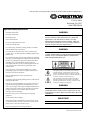
WARNING:
TO REDUCE THE RISK OF FIRE OR ELECTRIC SHOCK,
DO NOT EXPOSE THIS APPARATUS TO RAIN OR
MOISTURE. THE APPARATUS SHALL NOT BE
EXPOSED TO DRIPPING OR SPLASHING. OBJECTS
FILLED WITH LIQUIDS, SUCH AS VASES, SHOULD
NOT BE PLACED ON THE APPARATUS.
WARNING:
TO PREVENT ELECTRIC SHOCK, DO NOT REMOVE
COVER. THERE ARE NO USER SERVICEABLE PARTS
INSIDE. ONLY QUALIFIED SERVICE PERSONNEL
SHOULD PERFORM SERVICE.
The lightning flash with arrowhead symbol, within an
equilateral triangle, is intended to alert the user to the
presence of uninsulated “dangerous voltage” within the
product’s enclosure that may be of sufficient magnitude to
constitute a risk of electric shock to persons.
The exclamation point within an equilateral triangle is
intended to alert the user to the presence of important
operating and maintenance (servicing) instructions in the
literature accompanying the appliance.
WARNING:
THIS IS AN APPARATUS WITH CLASS I
CONSTRUCTION. IT SHALL BE CONNECTED TO AN
ELECTRICAL OUTLET WITH AN EARTHING GROUND
TERMINAL.
IMPORTANT:
The MPS-300 can be used with Class 2 output wiring.
All brand names, product names and trademarks are the property of their respective owners.
©2008 Crestron Electronics, Inc.

Crestron MPS-300 Multimedia Presentation System 300
Operations Guide – DOC. 6529B Contents • i
Contents
Multimedia Presentation System 300: MPS-300 1
Introduction ...............................................................................................................................1
Features and Functions................................................................................................1
Applications................................................................................................................. 4
Internal Block Diagram ............................................................................................... 5
Specifications ..............................................................................................................6
Physical Description..................................................................................................10
Industry Compliance .................................................................................................21
Setup ........................................................................................................................................ 22
Network Wiring.........................................................................................................22
CAT5 Wiring............................................................................................................. 22
QuickMedia Wiring...................................................................................................23
Installation.................................................................................................................24
Hardware Hookup .....................................................................................................25
Configure the RGB Input Ports ................................................................................. 28
Programming Software............................................................................................................31
Earliest Version Software Requirements for the PC .................................................31
Programming with Crestron SystemBuilder.............................................................. 31
Programming with SIMPL Windows ........................................................................31
Switching Programs...................................................................................................32
Saving Settings ..........................................................................................................32
Uploading and Upgrading........................................................................................................ 34
Establishing Communication..................................................................................... 34
Programs and Firmware ............................................................................................35
Configuration & Operation......................................................................................................36
Configuration............................................................................................................. 36
Operation...................................................................................................................76
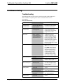
Problem Solving ......................................................................................................................84
Troubleshooting.........................................................................................................84
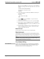
Check Network Wiring.............................................................................................. 86
Reference Documents................................................................................................ 87
Further Inquiries........................................................................................................88
Future Updates ..........................................................................................................88
Software License Agreement...................................................................................................89
Return and Warranty Policies.................................................................................................. 91
Merchandise Returns / Repair Service ...................................................................... 91
CRESTRON Limited Warranty................................................................................. 91


Crestron MPS-300 Multimedia Presentation System 300
Multimedia Presentation
System 300: MPS-300
Multimedia Presentation
System 300: MPS-300
Introduction Introduction
Features and Functions
• System switcher, audio processor, and control system
• Out-of-the-box switching and audio control
• Two video/HDTV and three RGB/computer inputs
• Three QuickMedia inputs with delay skew compensation
• Built-in input signal sensing | auto-switching capable
• Discrete composite, S-video, component, and RGB outputs
• Three QuickMedia™ and one Crestron Home
®
CAT5 AV outputs
• Five balanced stereo audio inputs
• Two gated mic inputs with compressor & limiter
• Eight-channel mic mixing w/4-band EQ per channel
• Discrete program, speech, and record outputs
• Graphic and parametric equalization | 40ms audio delay
• Built-in 40 watt amplifier — stereo (20 Watt x2), 70V, or 100V models
• 2-Series control engine | e-Control
®
2 Web server
• 10/100 Ethernet | RoomView and SNMP support
• Two RS-232, four IR, four digital in, & four relay control ports
• Front panel setup and control | Backlit LCD display
• Keypad, touchpanel, and wireless control options
• Internal power supply | 2-space rack-mountable
The MPS-300 is a complete presentation control and signal routing solution for
boardrooms and classrooms. Integrating the control system, multimedia matrix
switcher, mic mixer, audio processor, amplifier, and QuickMedia distribution center
all into a single 2-space rackmount package, the MPS-300 affords considerable
signal routing versatility and high-performance signal processing without the need
for separate components.
System Switcher
Right out of the box, the MPS-300 provides high-performance switching of two
video and three RGB computer sources to a single projector or plasma display.
Operations Guide – DOC. 6529B Multimedia Presentation System 300: MPS-300 • 1

Multimedia Presentation System 300 Crestron MPS-300
Composite, S-video, component and RGBHV signals can be routed to the
appropriate inputs on the display device, with control of the display provided via
Ethernet, RS-232 or IR. Input signal sensing is provided on every video and RGB
input to enable auto-switching functionality and provide device power status
information to the control system. Selectable sync impedance on the RGB inputs
helps accommodate cable runs of varying lengths.
Versatile matrix switching inside the MPS-300 actually affords some additional
hidden flexibility, providing discrete outputs for RGB, composite, S-video, and
component signals. For instance, Outputs 1 and 2 can function as separate composite
and S-video outputs, or as a single component output; Output 3 can be used for
component, S-video, or composite signals; and Output 4 can be used for either RGB
or component. Each output is fed by a separate matrix crosspoint, so they all can be
active simultaneously and assigned any relevant input source.
QuickMedia™ Matrix
In addition to its conventional type video inputs and outputs, the MPS-300
accommodates additional sources and display devices via Crestron's exclusive
QuickMedia (QM) transport. Three QM inputs accept connections from QM Wall
Plates, FlipTop Boxes, and Distribution Centers, providing an abundance of
additional inputs for AV, computer, and microphone sources. Three QM outputs are
also provided, each independently controllable to feed multiple displays and other
devices.
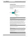
QuickMedia provides a very streamlined, low-cost, long-distance wiring solution.
The QuickMedia transport transmits high-resolution RGB, HD video, stereo program
and microphone audio signals up to 450 feet over a single inexpensive CAT5e type
cable*. Just one CresCAT-QM cable and a QM receiver are all that is required for
complete signal routing and device control, eliminating all the bulky, expensive
cabling that would otherwise be needed. A full range of QM transmitters, receivers,
and other products is offered by Crestron
®
to suit any application.
* For QuickMedia wiring use CresCAT-QM-P, CresCAT-QM-NP, CresCAT-IM-P, or quality
CAT5e/CAT6 cable with a delay skew of ≤15ns per 100m; the maximum aggregate cable length and
delay skew between any QM transmitter (origination point) and QM receiver (endpoint) is 450 ft
(137 m) and 22 ns; a maximum of two QM midpoint devices may be inserted in a given QM signal
path; exceptions apply, refer to each respective product manual for full detail.
Touchpanel Output
Any of the QM outputs may be utilized to feed a preview signal to the system
touchpanel. Additionally, one Crestron Home
®
(CH) CAT5 Balanced Video output
is included, its signal corresponding with the first QM output, providing for
simplified wiring to a complete range of Crestron touchpanels. Each QM output
supports high-resolution RGB and HDTV plus audio, while the CH output is limited
to standard video and HDTV only (dependent upon the capabilities of the
touchpanel).
8-Channel Microphone Matrix Mixing
Two gated microphone/line inputs are included on the MPS-300 complete with
software-switchable 48V phantom power and independently adjustable compression
and limiting. Up to six additional microphone signals can be brought in through the
three QM inputs, with 4-band speech-optimized equalization provided on all eight
mic channels. Sophisticated matrix mixing allows for six completely different mixes
of all eight microphones—three mixes feeding discrete “local” outputs, and three
additional mixes feeding the three QM outputs.
2 • Multimedia Presentation System 300: MPS-300 Operations Guide – DOC. 6529B

Crestron MPS-300 Multimedia Presentation System 300
Professional Audio Features
Five stereo audio inputs on the rear panel accept balanced or unbalanced line-level
signals from computers and other program audio sources. Additional audio sources
can be brought in through the three QM inputs. To accommodate a wide range of
signals, adjustable input compensation is employed to help maintain consistent
volume levels when switching between sources. Versatile matrix mixing allows the
selected program signal and the eight microphone signals to be separated or mixed in
any combination to feed three “local” outputs, each with its own unique mix.
Three discrete balanced line level outputs are provided, each with independent
adjustments for volume, bass, treble, and mute. The stereo (PROG OUT) and mono
(SPEECH) outputs are normally intended for driving external amplification, with
relay muting on each output to prevent “thumping” on power up. The record (REC
OUT) output allows for a completely separate stereo mix to feed a codec, recording
device, or assistive listening system. Ten-band graphic equalization plus 2-band
parametric equalization on each output eliminates the need for expensive outboard
audio processors, and up to 40ms delay adjustment is available on the SPEECH
output for proper loudspeaker alignment.
The three QM outputs are controlled separately from the other audio outputs,
allowing three different program sources and three different microphone mixes to be
monitored on touchpanels and output to additional audio equipment by way of an
appropriate QM receiver or other QuickMedia device(s).
Built-in Amplifier
A 40-watt amplifier is built into the MPS-300, with three models available offering
the choice of 8-ohm stereo, 70V mono, or 100V mono outputs. For large rooms
requiring more power, the MPS-300 supports plug-and-play compatibility with
Crestron's QM-Series 3-channel amplifiers, providing a complete solution for driving
a professional loudspeaker system with discrete program and speech channels.
Front Panel Control
Out of the box, the MPS-300 front panel supports easy pushbutton routing of input
sources to each of the outputs, and audio volume adjustment using the volume
control knob. Dedicated buttons and indicators are also provided for separate control
of system power and projector power. In addition, five preset buttons are included
for custom functions such as lowering a projection screen, closing blinds, or
selecting a lighting preset.
The front panel label strips are easily customized using Crestron Engraver software
or standard 3/8” tape labels, allowing for the clear designation of each input, output,
and preset button. When selected, these functions will also appear on the LCD
display as generic names (Input 1, 2…), or as custom names (DVD, Podium PC,
Screen Up, etc.) which are easily entered using the out-of-the-box functionality,
SIMPL™ Windows
®
software, or SystemBuilder software.
Easy setup of the MPS-300 is facilitated through the LCD display without
necessitating a computer. Together with four softkey buttons, four menu navigation
buttons and the volume knob, the LCD enables configuration of IP network, audio,
and other system settings. For security, the front panel controls can be password
protected or locked out.
2-Series Control System
Integrated into the MPS-300 is a Crestron 2-Series Ethernet control system complete
with e-Control
®
2 Web server and a host of RS-232, IR, digital input and relay
control ports for integration with third-party equipment. Anything from a basic AV
Operations Guide – DOC. 6529B Multimedia Presentation System 300: MPS-300 • 3

Multimedia Presentation System 300 Crestron MPS-300
presentation room with a single projector, screen, and keypad controller, to a fully
custom touchpanel based system with multiple controlled sources and display
devices, can be programmed easily using Crestron SystemBuilder™ software. And,
the MPS-300 works with Crestron's RoomView
®
Help Desk software, the industry's
most comprehensive facility-wide asset management solution.
Room Control Options
Without requiring any programming, the MPS-300 can be controlled simply using
Crestron's APAD LCD Controller or a selection of keypads. With custom
programming, Crestron's complete line of Isys
®
touchpanels and MediaManager
FlipTops is supported. Equipped with an optional CNXRMIRD IR receiver, the
MPS-300 allows any Crestron IR wireless touchpanel or handheld remote to be used
for a low-cost wireless control solution. Or, adding an RF wireless gateway or WiFi
access point enables use of a wide range of 1-way and 2-way RF wireless handheld
remotes and touchpanels.
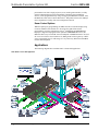
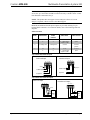
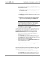
Applications
The following diagram shows an MPS-300 in a lecture hall application.
MPS-300 in a Lecture Hall Application
4 • Multimedia Presentation System 300: MPS-300 Operations Guide – DOC. 6529B

Crestron MPS-300 Multimedia Presentation System 300
For more information on this and other QM applications, refer to the latest revision
of the Crestron MediaManager Applications Guide (Doc. 6244), which is available
from the Crestron website (
http://www.crestron.com/manuals).
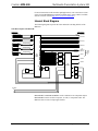
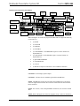
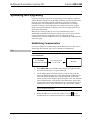
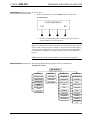
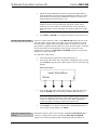
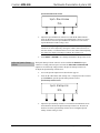
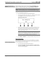
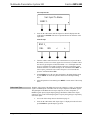
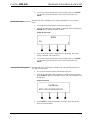
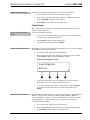
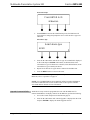
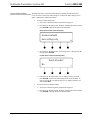
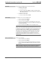
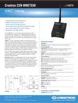
Internal Block Diagram
The following diagrams represent the video and audio switching abilities of the
MPS-300.
Video Block Diagram of the MPS-300
8x7
Matrix
Switch
Composite
VIDEO INPUTS
S-Video
Component
RGBHV
QM INPUTS
QM OUT 6
VIDEO OUTPUTS
RGBHV
RGBHV
RGBHV
1
2
3
4
5
QM to
Analog
RGBHV
Analog
to QM
QM OUT 7
6
7
CH
Balanced
Video OUT
RGBHV
QM OUT
TOUCH
PANEL
PORT
(Composite/
S-Video/
Component)
8
LOCAL OUT 1
5
LOCAL OUT 2
LOCAL OUT 3
LOCAL OUT 4
RGB Signal Detection
RGB Signal Detection
RGB Signal Detection
Composite/S-Video/YPbPr
Composite/S-Video/YPbPr
Composite/S-Video/
YPbPr Signal Detection
Composite/S-Video/
YPbPr Signal Detection
Analog
to QM
Analog
to QM
QM to
Analog
QM to
Analog
RGB
Delay
LP
Filter
RGBHV
RGBHV
6x6
QM Matrix
LOCAL OUT 1 and LOCAL OUT 2 can be combined to one component output.
LOCAL OUT 3 can be used for composite, S-video, or component video. The
MPS-300 does not convert input signal formats.
Operations Guide – DOC. 6529B Multimedia Presentation System 300: MPS-300 • 5

Multimedia Presentation System 300 Crestron MPS-300
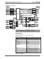
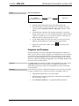
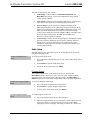
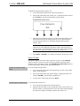
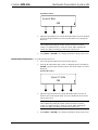
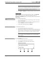
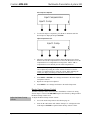
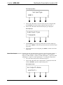
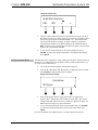
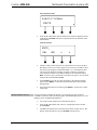
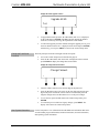
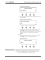
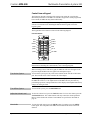
Audio Block Diagram of the MPS-300
8x4
Matrix
Switch
AUDIO INPUTS
QM OUT5
(Touchpanel)
Stereo Audio
1
2
3
4
5
QM OUT6
6
A/D
A/D
A/D
A/D
A/D
7
QM Audio
Combiner
QM Audio
Combiner
QM IN
QM IN
Stereo Audio
Stereo Audio
Stereo Audio
Stereo Audio
Local Mic
Local Mic
1
2
Mic1&2
Vol/EQ
10 Channel
Stereo Mixer
L
R
Vol/EQ
Mute
Mute
Speech
Program L
Program R
With Phantom Power
With Phantom Power
8
QM IN
Mic1&2
QM OUT7
QM Audio
Combiner
Vol/EQ
Mic1&2
Stereo Program Audio
Vol/EQ
Mute
Record L
Record R
8 Individual Microphone Channels
10 Channel
Mono Mixer
10 Channel
Stereo Mixer
L
R
4/8Ω Model
L
R
70V/100V Models
Delay
8x2
Channel
Mic Mixer
8x2
Channel
Mic Mixer
8x2
Channel
Mic Mixer
COMP/LIMIT
GATE
COMP/LIMIT
GATE
AUDIO OUTPUTS
AD/
D/A
D/A
D/A
D/A
40W
Amp
20Wx2
Amp
A/D
A/D
Program/Mic
Splitter
Program/Mic
Splitter
Program/Mic
Splitter
NOTE: The MPS-300-70V and MPS-300-100V amplify the SPEECH output audio
path while the MPS-300 amplifies the PROGRAM output audio path.
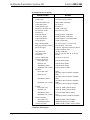
Specifications
Specifications for the MPS-300 are listed in the following table.
MPS-300 Specifications
SPECIFICATION DETAILS
Processor
CPU
32-bit Freescale ColdFire
®
Microprocessor
Memory
SDRAM
NVRAM
Flash
32 MB
256 KB
16 MB
Operating System
Real-time, preemptive, multitasking kernel,
multi-threaded; FAT32 file system with long
names; supports SIMPL Windows and
SIMPL+
®
Ethernet
10/100BaseT, static IP or DHCP/DNS, SSL,
auto-negotiating, full duplex TCP/IP,
UDP/IP, CIP, SMTP, SNMP, built-in Web
server and e-mail client; supports Crestron
e-Control
®
2 XPanel and RoomView
®
applications
(Continued on following page)
6 • Multimedia Presentation System 300: MPS-300 Operations Guide – DOC. 6529B

Crestron MPS-300 Multimedia Presentation System 300
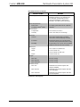
MPS-300 Specifications (Continued)
SPECIFICATION DETAILS
Video/RGB
Switcher
Signal Types
Video/HDTV Formats
RGB Formats
Maximum Resolution
Blanking Time
Sync Rise/Fall Time
Sync Latency
Gain
QM Cable Compensation
8x7 crosspoint matrix including 3x3 QM
signal routing, QM delay skew
compensation
RGB and composite, S-video, or
component video (does not transcode)
NTSC or PAL, HDTV up to 1080i/1080p
RGBHV or RGBS
QXGA 2048 x 1536 @ 60Hz
(WUXGA 1920 x 1200 @ 60Hz via QM)
< 0.1 second
3.5 ns maximum
< 30 ns
0dB (75 ohms terminated)
10-bit digitally controlled PEAK (bandwidth)
and BOOST (frequency); 4-bit digitally
controlled SKEW delay, 0 to 22 ns
(independent for R, G, and B)
Audio
Switcher/Preamp
A-D/D-A Conversion
Output Volume Range
Mixer Volume Range
Mute
Input Compensation
Mic Input Gain
Gate Level (Threshold)
Gate Attack Time
Gate Decay (Release) Time
Gating Depth
Compressor Curve
Compressor Threshold Level
Compressor Attack Time
Compressor Release Time
Compression Ratio
8x4 stereo crosspoint matrix including 3x3
QM signal routing, 2-channel gated mic
preamp with compressor and limiter,
8-channels mic EQ, 10x5 mic/program
matrix mixer, 8x2 mic matrix mixer per each
of 3 QM outputs, stereo volume/tone control
and EQ per each of PROGRAM and
RECORD outputs, mono volume/tone
control and EQ/delay on SPEECH output,
integrated power amplifier, QM auto-
compensation with self-peaking
24-bit, 48 kHz
-80dB to +20dB, 0.1dB steps
-80dB to 0dB, 0.1dB steps
-100dB (electronic), -120dB (relay)
±10dB, 0.1dB steps
0 to 100% (40dB range) plus mute
0 to 100%
0 to 100 ms
0 to 5000 ms
-80dB to 0dB, 0.1dB steps
Selectable hard or soft knee
-80dB to 20dB, 0.1dB steps
0.1 to 300 ms
1 to 500 ms
1:1 (no compression) to
10:1 (maximum compression)
(Continued on following page)
Operations Guide – DOC. 6529B Multimedia Presentation System 300: MPS-300 • 7

Multimedia Presentation System 300 Crestron MPS-300
MPS-300 Specifications (Continued)
SPECIFICATION DETAILS
Audio (continued)
Limiter Curve
Limiter Threshold Level
Limiter Attack Time
Limiter Release Time
Microphone EQ Filter Gain
Mic EQ Filter Center
Frequencies
Bass Gain Range
Treble Gain Range
Output Equalization
PEQ Filter Gain
PEQ Filter Bandwidth
PEQ Filter Center Frequency
PEQ Filter Types
GEQ Filter Gain
GEQ Filter Center
Frequencies
Speech Output Delay
Frequency Response
PROG/REC OUT
SPEECH OUT
SPEAKER (8 ohms)
SPEAKER (70V or 100V)
S/N Ratio
PROG/REC OUT
SPEECH OUT
SPEAKER (8 ohms)
SPEAKER (70V or 100V)
THD+N
PROG/REC OUT
SPEECH OUT
SPEAKER (8 ohms)
SPEAKER (70V or 100V)
Stereo Separation
PROG/REC OUT
SPEAKER (8 ohms)
Channel Crosstalk
Selectable hard or soft knee
0dB to 20dB, 0.1dB steps
0.1 to 300 ms
1 to 500 ms
±12dB, 0.1dB steps
160, 500, 1.2k, 3k Hz
±12dB @ 100Hz, 0.5dB steps
±12dB @ 10kHz, 0.5dB steps
10-band graphic + 2-band parametric
±12dB, 0.1 dB steps
0.1 to 3.0 octaves, 0.1 octave steps
25Hz to 20kHz, 0.5Hz steps
Low Pass, High Pass, Peaking Eq, Notch,
Treble Shelf, Bass Shelf
±12dB, 0.1dB steps
31.5, 63, 125, 250, 500, 1k, 2k, 4k, 8k,
16k Hz
0 to 40 ms, 1 ms steps
20Hz to 20kHz ±0.5dB
50Hz to 20kHz ±0.5dB
20Hz to 20kHz ±0.5dB
100Hz to 20kHz ±1.5dB
95dB
(@ 10dBV, 20Hz to 20kHz A-weighted)
95dB
(@ 10dBV, 50Hz to 20kHz A-weighted)
90dB
(full output, 20Hz to 20kHz A-weighted)
90dB
(full output, 20Hz to 20kHz A-weighted)
0.02% (@ 10dBV, 20Hz to 20kHz)
0.02% (@ 10dBV, 50Hz to 20kHz)
0.7% (full output, 20Hz to 20kHz)
0.7%
(full output, 100Hz to 20kHz A-weighted)
-80dB (@ 10dBV, 20Hz to 20kHz)
-60dB (full output, 20Hz to 20kHz
-80dB (AUD IN @ 10dBV, 20Hz to 20kHz)
(Continued on following page)
8 • Multimedia Presentation System 300: MPS-300 Operations Guide – DOC. 6529B

Crestron MPS-300 Multimedia Presentation System 300
MPS-300 Specifications (Continued)
SPECIFICATION DETAILS
LCD Display
Green LCD alphanumeric, adjustable
backlight. Two lines x 20 characters per
line. Displays input/outputs by name,
volume level bargraph, setup menus,
time/date, and other system information
Power Requirements
Main Power
Available Cresnet
®
Power
2.5 Amps @ 100-240 Volts AC, 50/60 Hz
30 Watts
Environmental
Temperature
Humidity
41° to 104°F (5° to 40°C)
10% to 90% RH (non-condensing)
Enclosure
Chassis
Faceplate
Mounting
Steel, black matte powder coat finish,
convection-cooled, vented top and sides
Extruded aluminum, black matte powder
coat finish with polycarbonate label overlay
Freestanding or 2U 19-inch rack-mountable
(adhesive feet and rack ears included)
Dimensions
Height
Width
Depth
3.47 in (8.81 cm) without feet
17.03 in (43.24 cm);
19.00 in (48.26 cm) with ears
12.58 in (31.95 cm)
Weight:
MPS-300
MPS-300-70V
MPS-300-100V
10.1 lbs (4.6 kg)
11.9 lbs (5.4 kg)
11.3 lbs (5.4 kg)
Available Models:
MPS-300
MPS-300-70V
MPS-300-100V
Multimedia Presentation System 300
w/Stereo Amplifier
Multimedia Presentation System 300 with
70 Volt Amplifier
Multimedia Presentation System 300 with
100 Volt Amplifier
(Continued on following page)
Operations Guide – DOC. 6529B Multimedia Presentation System 300: MPS-300 • 9

Multimedia Presentation System 300 Crestron MPS-300
MPS-300 Specifications (Continued)
SPECIFICATION DETAILS
Available Accessories:
APAD
C2N-DB12
C2N-FTB
C2N-MNETGW
CLS-C6(M)
CLW-DIM1RF and
CLW-SW1RF
CNSP-XX
CNX-B12
CNXRMIRD
IRP2
QM-AMP3X80MM
QM-AMP3X80SR
Wall Mount LCD Controller
12-Button Decorator Keypad
FlipTop Control Center
infiNET™ Gateway
iLux™ Integrated Lighting System
infiNET Dimmer and Switch
Custom Serial Interface Cable
12-Button Designer Keypad
IR Receiver
IR Probe
3-Channel Multimedia Amplifier
3-Channel Sound Reinforcement Amplifier
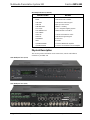
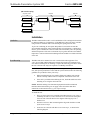
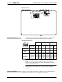
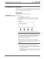
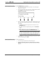
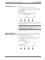
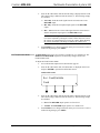
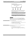
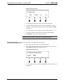
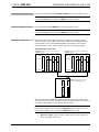
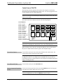
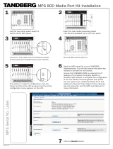
Physical Description
This section provides information on the connections, controls and indicators
available on your MPS-300.
MPS-300 Physical View (Front)
MPS-300 Physical View (Rear)
10 • Multimedia Presentation System 300: MPS-300 Operations Guide – DOC. 6529B

Crestron MPS-300 Multimedia Presentation System 300
MPS-300 Overall Dimensions
17.03 in
(43.24 cm)
3.47 in
(8.81 cm)
11.85 in
(30.08 cm)
12.58 in
(31.95 cm
)
Operations Guide – DOC. 6529B Multimedia Presentation System 300: MPS-300 • 11

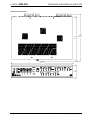
Multimedia Presentation System 300 Crestron MPS-300
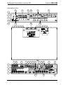
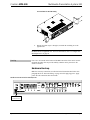
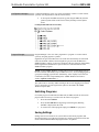
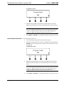
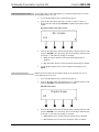
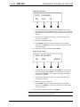
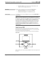
MPS-300 Buttons and Ports
1
2
3
4
5
6
8
9
10
11
12
14 16
17
19
20
30
18 21
23
24
22 2725 29
31
32
34
15 28
26
7
13
33
12 • Multimedia Presentation System 300: MPS-300 Operations Guide – DOC. 6529B

Crestron MPS-300 Multimedia Presentation System 300
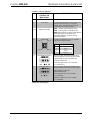
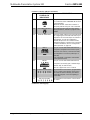
Connectors, Controls & Indicators
#
CONNECTORS
1
,
CONTROLS &
INDICATORS
DESCRIPTION
1 NET LED (1) yellow LED, indicates Cresnet bus activity.
2 MSG LED
(1) yellow LED, illuminates when a message is
present in the message log. To view the
contents of the message log, use the front
panel buttons or Crestron Toolbox™.
3 & 4 RESET BUTTONS
HW-R – Initiates system hardware reset.
SW-R – Pressing this in combination with
HW-R button performs a system restart without
loading the program. Pressing it alone
momentarily while the system is running
restarts the program.
5
COMPUTER
Pin 1 Pin 2
Pin 4 Pin 3
(1) USB Type B female; USB 1.1 computer
console port (cable included)
PIN DESCRIPTION
1 +5 VDC
2 Data -
3 Data +
4 Ground
6
PROGRAM OUT (L/R)
(1) 5-pin 3.5 mm detachable terminal block;
Balanced/unbalanced stereo line-level output;
Output Impedance: 200 ohms balanced,
100 ohms unbalanced;
Maximum Output Level: 4 V
rms
balanced,
2 V
rms
unbalanced
7
AUDIO INPUTS 1-5
(5) 5-pin 3.5 mm detachable terminal blocks;
Balanced/unbalanced stereo line-level inputs;
Input Impedance: 24k ohms
balanced/unbalanced;
Balanced Input Level: -20 to +12 dBV;
4 V
rms
maximum;
Unbalanced Input Level: -20 to +6 dBV;
2 V
rms
maximum
(Continued on following page)
Operations Guide – DOC. 6529B Multimedia Presentation System 300: MPS-300 • 13

Multimedia Presentation System 300 Crestron MPS-300
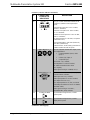
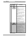
Connectors, Controls & Indicators (Continued)
#
CONNECTORS
1
,
CONTROLS &
INDICATORS
DESCRIPTION
8
MC/LN 1 – 2
(2) 5-pin 3.5 mm detachable terminal blocks;
Comprises (2) Balanced microphone/line
inputs;
Balanced Mic Input Level: -52 to -12 dBV,
240 mV
rms
maximum;
Balanced Line Input Level: -28 to +11 dBV;
3.7 V
rms
maximum;
Unbalanced Line Input Level: -34 to +5 dBV;
1.85 V
rms
maximum;
Mic Input Impedance: 3.9k ohms, accepts 60
to 600 ohm source;
Line Input Impedance: 19k ohms (balanced),
9.5k ohms (unbalanced);
Phantom Power: 10 mA (total) @ 48 Volts DC,
software enabled to both mic inputs
9
VIDEO INPUTS 1 - 2
RGBHV INPUTS 3 - 5
(2) sets of (3) BNC female video inputs, each
set configurable as:
• Component/HDTV (YP
b
P
r
) video
input, or
• S-video (Y/C) input, or
• Composite input
Input Level: 1 V
p-p
nominal;
Input Impedance: 75 ohms nominal;
DC Offset: Insensitive to DC offset
(AC coupled);
Video signal sensing on COMP/P
b
or Y/Y
(3) DB15HD female, RGBHV (VGA) inputs;
Format: RGBHV or RGBS;
RGB Input Level: 1 V
p-p
nominal;
RGB Input Impedance: 75 ohms nominal;
Sync Input Level: 2 to 5 V
p-p
;
Sync Input Impedance: 75, 500, or 1k ohms
individually selectable for H and V via bottom
panel DIP switch;
Video signal sensing on “H-SYNC”;
Defeatable DDC pull-up resistors
10
SYSTEM POWER
(1) pushbutton and green LED, controls
system power
11
PROJECTOR POWER
(1) pushbutton and green LED, controls
display device power
(Continued on following page)
14 • Multimedia Presentation System 300: MPS-300 Operations Guide – DOC. 6529B

Crestron MPS-300 Multimedia Presentation System 300
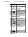
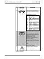
Connectors, Controls & Indicators (Continued)
#
CONNECTORS
1
,
CONTROLS &
INDICATORS
DESCRIPTION
12
REC OUT
(1) 5-pin 3.5 mm detachable terminal block;
Balanced/unbalanced, stereo line-level output;
Output Impedance: 200 ohms balanced,
100 ohms unbalanced;
Maximum Output Level: 4 V
rms
balanced,
2 V
rms
unbalanced
NOTE: Does not include relay mute.
13
SPEECH OUT
(1) 3-pin 3.5 mm detachable terminal block;
Balanced/unbalanced mono line-level output;
Output Impedance: 200 ohms balanced,
100 ohms unbalanced;
Maximum Output Level: 4 V
rms
balanced,
2 V
rms
unbalanced
14
LCD DISPLAY AND
SOFT BUTTONS
Green LCD alphanumeric, adjustable
backlight; 2 lines x 20 characters per line;
Displays input/outputs by name, volume level
bargraph, setup menus, time/date, and other
system information
(4) pushbuttons for activation of LCD driven
functions and passcode entry
15
SPEAKER OUTPUTS
(1 or 2) 2-pin 5 mm detachable terminal
blocks; Speaker-level audio outputs
(MPS-300);
(1) 2-pin 5 mm detachable terminal blocks;
Speaker-level audio outputs (MPS-300-70V
and MPS-300-100V)
Wire Size: Connector accepts 12 AWG
maximum
Output Power (MPS-300): 20W RMS per
channel stereo into 8 ohms, 4 ohms tolerant;
Output Power (MPS-300-70V): 40W RMS
mono at 70 Volts;
Output Power (MPS-300-100V): 40W RMS
mono at 100 Volts
16
NAVIGATION
BUTTONS
(4) Pushbuttons for navigating the
configuration menus of the MPS-300
17
IR/SERIAL OUT
(4) 2-pin 3.5 mm detachable terminal blocks,
IR/Serial output ports; IR output up to 1.2 MHz;
One-way serial TTL/RS-232 (0-5 Volts)
2
up to
9600 baud
(Continued on following page)
Operations Guide – DOC. 6529B Multimedia Presentation System 300: MPS-300 • 15

Multimedia Presentation System 300 Crestron MPS-300
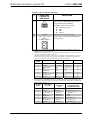
Connectors, Controls & Indicators (Continued)
#
CONNECTORS
1
,
CONTROLS &
INDICATORS
DESCRIPTION
18
IR IN
(1) 3-pin 3.5 mm detachable terminal block;
For connection of the CNXRMIRD IR Receiver
(sold separately);
Allows IR wireless control from Crestron or
third-party remotes using RC-5 IR commands.
19
VOLUME CONTROL
(1) Continuous turn rotary encoder, adjusts
menu parameters, defaults to program audio
volume
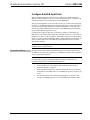
20 RGB DIP SWITCHES
(3) Banks of DIP switches (one per RGB input)
for configuring the horizontal and vertical sync
impedances of each RGB input. Each bank of
DIP switches can also be configured to
simulate the presence of a monitor to RGB
outputs that require a monitor to be connected.
For more information, refer to “Configure the
RGB Input Ports” on page 28.
21
INPUT
(1) 5-pin 3.5 mm detachable terminal block;
Comprises (4) digital/contact closure inputs;
Rated for 0-24 Volts DC, referenced to GND;
Input Impedance: 2.2k ohms pulled up to 5
Volts DC;
Logic Threshold: 2.5 Volts DC nominal with
1 Volt hysteresis band
22
RELAY
(1) 8-pin 3.5 mm detachable terminal block;
Comprises (4) normally open, isolated relays;
Rated 1 Amp, 30 Volts AC/DC;
MOV arc suppression across contacts
23
FUNCTION BUTTONS
(5) pushbuttons and red LEDs, programmable
for any control system function. When using
the out-of-the-box functionality, the buttons
control the projector screen and lighting (if
connected).
24
INPUT BUTTONS (8) pushbuttons and red LEDs, select input to
be routed.
(Continued on following page)
16 • Multimedia Presentation System 300: MPS-300 Operations Guide – DOC. 6529B
Page is loading ...
Page is loading ...
Page is loading ...
Page is loading ...
Page is loading ...
Page is loading ...
Page is loading ...
Page is loading ...
Page is loading ...
Page is loading ...
Page is loading ...
Page is loading ...
Page is loading ...
Page is loading ...
Page is loading ...
Page is loading ...
Page is loading ...
Page is loading ...
Page is loading ...
Page is loading ...
Page is loading ...
Page is loading ...
Page is loading ...
Page is loading ...
Page is loading ...
Page is loading ...
Page is loading ...
Page is loading ...
Page is loading ...
Page is loading ...
Page is loading ...
Page is loading ...
Page is loading ...
Page is loading ...
Page is loading ...
Page is loading ...
Page is loading ...
Page is loading ...
Page is loading ...
Page is loading ...
Page is loading ...
Page is loading ...
Page is loading ...
Page is loading ...
Page is loading ...
Page is loading ...
Page is loading ...
Page is loading ...
Page is loading ...
Page is loading ...
Page is loading ...
Page is loading ...
Page is loading ...
Page is loading ...
Page is loading ...
Page is loading ...
Page is loading ...
Page is loading ...
Page is loading ...
Page is loading ...
Page is loading ...
Page is loading ...
Page is loading ...
Page is loading ...
Page is loading ...
Page is loading ...
Page is loading ...
Page is loading ...
Page is loading ...
Page is loading ...
Page is loading ...
Page is loading ...
Page is loading ...
Page is loading ...
Page is loading ...
Page is loading ...
-
 1
1
-
 2
2
-
 3
3
-
 4
4
-
 5
5
-
 6
6
-
 7
7
-
 8
8
-
 9
9
-
 10
10
-
 11
11
-
 12
12
-
 13
13
-
 14
14
-
 15
15
-
 16
16
-
 17
17
-
 18
18
-
 19
19
-
 20
20
-
 21
21
-
 22
22
-
 23
23
-
 24
24
-
 25
25
-
 26
26
-
 27
27
-
 28
28
-
 29
29
-
 30
30
-
 31
31
-
 32
32
-
 33
33
-
 34
34
-
 35
35
-
 36
36
-
 37
37
-
 38
38
-
 39
39
-
 40
40
-
 41
41
-
 42
42
-
 43
43
-
 44
44
-
 45
45
-
 46
46
-
 47
47
-
 48
48
-
 49
49
-
 50
50
-
 51
51
-
 52
52
-
 53
53
-
 54
54
-
 55
55
-
 56
56
-
 57
57
-
 58
58
-
 59
59
-
 60
60
-
 61
61
-
 62
62
-
 63
63
-
 64
64
-
 65
65
-
 66
66
-
 67
67
-
 68
68
-
 69
69
-
 70
70
-
 71
71
-
 72
72
-
 73
73
-
 74
74
-
 75
75
-
 76
76
-
 77
77
-
 78
78
-
 79
79
-
 80
80
-
 81
81
-
 82
82
-
 83
83
-
 84
84
-
 85
85
-
 86
86
-
 87
87
-
 88
88
-
 89
89
-
 90
90
-
 91
91
-
 92
92
-
 93
93
-
 94
94
-
 95
95
-
 96
96


Crestron Multimedia Presentation System 300 MPS-300 User manual
- Category
- Networking
- Type
- User manual
- This manual is also suitable for
Ask a question and I''ll find the answer in the document
Finding information in a document is now easier with AI
Related papers
-
Crestron MPS-100 User manual
-
-
-
-
-
Crestron QuickMedia QM-AMP3X80SR User manual
-
-
-
Crestron QM-TX User manual
-
Other documents
-
 Crestron electronic MPS-250 User manual
-
Key Digital FATBOY KD-MSW4X2 User manual
-
Audiovox VSIR100B User manual
-
Ask ADSW0012M1 User manual
-
 Crestron electronic C2N-MNETGW User manual
-
Channel Vision WA-350 Datasheet
-
 Crestron electronic TPS Series User manual
-
 TANDBERG MPS 800 Installation guide
-
 Crestron electronic TPS-15L User manual
-
AMX Network Card DAS-MNET User manual


