high pass
high pass
Troubleshooting
PHANTOM MOSFET Amplifier User’s Manual - page 15
Specifications
PHANTOM MOSFET Amplifier User’s Manual - page 16
PHANTOM MOSFET Amplifier User’s Manual - page 5
PHANTOM MOSFET Amplifier User’s Manual - page 12
PHANTOM MOSFET Amplifier User’s Manual - page 13
CONTENTS
PHANTOM MOSFET Amplifier User’s Manual - page 1
U S E R ’ S M A N U A L
PHANTOM MOSFET Amplifier User’s Manual - page 4
General precautions
PHANTOM MOSFET Amplifier User’s Manual - page 3
Features About 2 Ohm operation
PHANTOM MOSFET Amplifier User’s Manual - page 6
PHANTOM MOSFET Amplifier User’s Manual - page 11
PHANTOM MOSFET Amplifier User’s Manual - page 10
PHANTOM MOSFET Amplifier User’s Manual - page 8
PHANTOM MOSFET Amplifier User’s Manual - page 14
PHANTOM MOSFET Amplifier User’s Manual - page 7
PHANTOM MOSFET Amplifier User’s Manual - page 9
If you experience operation or performance problems with this product, compare your
installation with the electrical wiring diagram on the previous pages. If problems persist,
read the following troubleshooting tips which may help eliminate the problems.
Before doing any wiring, look through
this manual and identify the diagrams
to follow for power, input and speaker
connections for your particular
installation. Be sure you understand
all the connections before you proceed.
1. Connect the power ground terminal
to the closest point on the chassis of
the car. Keep this ground wire to less
than 39" (100 cm) in length. Use 8
gauge (or heavier) wire.
2. Connect the remote terminal to the
remote output of the head unit using
16 gauge (or heavier) wire.
3. Connect an empty fuse holder within
18" (45 cm) of the car battery, and run
8 gauge (or heavier) cable from this
fuse to the amplifier location.
4. Check that the fuse holder is empty.
Then connect the fuse holder to the
"BATT+" connection on the amplifier.
5. If multiple amplifiers are being used
in your system, either:
• Run a separate pair of cables from
the battery and a chassis ground point
to each amplifier. Each (+) cable must
have its own inline fuse.
-or-
• Run a #4 cable from the fuse holder
at the battery to a distribution block
at or near the amplifier's location. Then
run separate cables from the amplifier
to this distribution block and to
independent chassis ground points.
6. Connect all line inputs and outputs
(if used) using high-quality cables.
Connect all speakers, following the
diagrams in this manual. Be sure to
observe proper polarity to avoid audio
phase problems.
Connecting the amplifier
Protection LED
comes on when
amplifier is
powered up.
Check for short circuits on speaker leads.
Turn down the volume control on the head unit to prevent overdriving.
Remove speaker leads, and reset the amplifier. If the Protection LED still
comes on, then the amplifier is faulty and needs servicing.
High hiss in the
speakers.
Disconnect all RCA inputs to the amplifiers. If the hiss disappears, then
plug in the component driving the amplifier and unplug its inputs. If the
hiss disappears at this point, go on until the faulty/noisy component is
found.
It is best to set the amplifier's input level control as low as possible. The
best subjective signal-to-noise ratio is achieved in this manner. Try to set
the head unit as high as possible (without distortion) and the amp input
level as low as possible.
Squealing noise
from speakers.
Check for improperly grounded RCA interconnects.
Distorted sound.
Check that the Input Level Control is set to match the signal level of the
head unit. Always try to set the Input Level as low as possible.
Check that all crossover frequencies are properly set.
Check for short circuits on the speaker leads.
Amplifier gets
very hot.
Check that the minimum speaker impedance for the amp model is correct.
Check that there is good air circulation around the amp. In some
applications, it may be necessary to add external cooling fan(s).
Engine noise
(static type)
This is usually caused by poor quality RCA cables,which can pick up
radiated noise. Use only the best quality cables, and route them away
from power cables.
Engine noise
(alternator
whine)
Check that speaker leads are not shorted to the vehicle chassis.
Check that the RCA grounds are not shorted to the vehicle chassis.
Check that the head unit is properly grounded.
Tri-Mode
Before installing and using your
new amplifier, please be-
come familiar with all the infor-
mation contained in this manual.
Please keep this manual in a safe
place for future reference.
• Do not open or attempt to repair
this unit yourself. Dangerous high
voltages are present which may result
in electric shock. Refer any repairs to
a qualified service technician.
• To avoid risk of electronic shock or
damage to the amplifier, do not permit
any of this equipment to become
damp or wet from water or drinks. If
this does occur, immediately unplug
the power wires and send the amplifier
to your local dealer or service center
as soon as possible.
• If there is smoke or any peculiar
odor present during use or if there is
damage to any of the component
enclosures, immediately unplug the
power wire and send the amplifier to
your local dealer or service center as
soon as possible .
7. Insert fuse(s) into the battery fuse
holder(s).
8. Recheck all connections before
powering up the amplifier.
9. Set all level controls to minimum
position, and set all crossover
controls/switches to the desired
frequency points.
10. Power up the head unit and the
amplifier. Then set the volume control
on the head unit to about 3/4 volume,
and adjust the amplifier’s input level
control(s) to just below the level of
distortion.
11. Further fine tuning of the various
controls may be necessary to obtain best
results.
Your PHANTOM amplifier has been
designed to operate efficiently at loads
down to 2 Ohms. This means that you
can install four 8 Ohm speakers per
channel, when using parallel wiring.
Increasing the number of woofers per
channel at low frequencies (below
100Hz) produces an acoustic coupling
effect. This acoustic coupling effect
increases your power output by about
3dB per speaker, or the equivalent of
an additional 10W per speaker.
When operating at 2 Ohms, the
amplifiers will increase their output
power by approximately 50%. The
current draw will also increase by
about the same amount, so be sure
you have enough current to run the
amplifiers into a 2 Ohm load.
If you lack adequate current, your
music reproduction will be distorted.
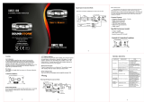
Low-level (RCA) input wiring is preferred for best audio performance. Always use
a high-quality RCA cable for best audio performance.
Tri-Mode
RIGHT
Speaker
LEFT
Speaker
To Audio
Outputs of head
unit or signal
processor
amplifier
The high level input(s) should only be used when your head unit lacks RCA outputs.
If the RCA outputs are not present, connect the speaker outputs from the receiver
to the high level input connector of the amplifier. Be sure to observe polarity to
avoid audio phase problems.
Low-level (RCA) input wiring is preferred for best audio performance. Always use
a high-quality RCA cable for best audio performance.
The high level input(s) should only be used when your head unit lacks RCA outputs.
If the RCA outputs are not present, connect the speaker outputs from the receiver
to the high level input connector of the amplifier. Be sure to observe polarity to
avoid audio phase problems.
MonoBlock Amplifier
PH2.500, PH2.600, PH2.800,
PH2.1000, PH2.1300, and PH2.1500
PH2.500, PH2.600, PH2.800,
PH2.1000, PH2.1300, and PH2.1500
PH4.400, PH4.500, PH4.600 and PH4.700
PH2.500, PH2.600, PH2.800,
PH2.1000, PH2.1300, and PH2.1500
PH4.400, PH4.500, PH4.600 and PH4.700
To Audio
Outputs of head
unit or signal
processor
RIGHT
Speaker
2 Introduction
2 What is included?
3 Features
3 About 2 Ohm operation
4 General precautions
4 Installation precautions
4 Mounting the amplifier
5 Connecting the amplifier
6 Low level input wiring
9 High level input wiring
10 2CH Power and Speaker wiring
2CH and Bridged Modes
11 2CH Power and Speaker wiring
TriMode
12 4CH Power and Speaker wiring
4CH and Bridged Modes
13 4CH Power and Speaker wiring
TriMode
14 MonoBlock Power
and
Speaker wiring
15 Troubleshooting
16 Specifications
Congratulations on your
purchase of a
PHANTOM Amplifier.
It has been designed, engineered
and manufactured to bring you
the highest level of performance
and quality, and will afford you
years of listening pleasure.
Thank you for making
your choice for car audio
entertainment!
All specifications subject to change without notice.
page
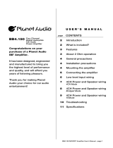
MAX POWER
into 2 Ohms
RMS POWER
into 4 Ohms
BRIDGED POWER
into 4 Ohms
Min. speaker
impedance
THD
Frequency response
Signal-to-noise ratio
Channel separation
Damping factor
Crossover range
low pass
high pass
Bass boost
Fuse rating
Dimensions:
9-1/2" x 2-1/4" x ...
(241mm x 57.2mm x...)
MODEL
4-Channel
MOSFET Amplifiers
MAX POWER
into 2 Ohms
RMS POWER
into 4 Ohms
BRIDGED POWER
into 4 Ohms
Min. speaker
impedance
THD
Frequency response
Signal-to-noise ratio
Channel separation
Damping factor
Crossover range
low pass
high pass
Bass boost
Fuse rating
Dimensions:
9
-1/2
" x 2
-1/4
" x ...
(241mm x 57.2mm x...)
MODEL
2-Channel MOSFET Amplifiers
MonoBlock
MOSFET
Amplifiers
2500W x 1
580W X 1
n/a
2 Ohm Stereo
4 Ohm Mono Bridged
0.01%
9Hz-50kHz
103dB
90dB
125+
35Hz-160Hz
200Hz (fixed)
Variable 0 - +18dB
25A x 2
14"
(356mm)
PH2500M
SYMPTOM POSSIBLE REMEDY
Do not mistake the input level control
for a volume control! It is designed
ONLY to match the output level of
your audio source to the input level
of your amplifier.
Do not adjust this input level to
maximum unless your input level
requires it.
Ignoring these instructions will result
in an input overload to the amplifier,
and excessive audio distortion. It
can also cause the protection circuit
to engage.
Don't misuse the
level control!
Two
Channel
Mode
MonoBlock
Mode
Connect the Positive (+) terminal of the
subwoofer to the L (+) amplifier terminal.
Connect the Negative (-) terminal of the
subwoofer to the R (-) amplifier terminal.
Bridged
Mode
Four
Channel
Mode
Bridged
Mode
Connect the Negative (-) terminal of the RIGHT subwoofer to
the CH2 (-) amplifier terminal.
Connect the Positive (+) terminal of the RIGHT subwoofer to
the CH1 (+) amplifier terminal.
Connect the Negative (-)
terminal of the LEFT
subwoofer to the CH4 (-)
amplifier terminal.
Connect the Positive (+)
terminal of the LEFT
subwoofer to the CH3 (+)
amplifier terminal.
To FRONT Audio Outputs of
head unit or
signal processor
To REAR Audio Outputs of
head unit or
signal processor
To Speaker Terminals
of head unit
To Speaker Terminals
of head unit
To Speaker
Terminals
of head unit
To Speaker
Terminals
of head unit