Page is loading ...

109444-03 - 12/19
9700609
FORCE
• Water Boiler
• Cast Iron
• Chimney Vent
• Gas Fired
TO THE INSTALLER:
Affix these instructions adjacent to boiler.
Provide model number and serial number when
seeking information and support.
TO THE CONSUMER:
Retain these instructions for future reference.
Contact heating contractor for all issues and support.
Models:
• FORCE02E
• FORCE03E
• FORCE04E
• FORCE05E
• FORCE06E
• FORCE07E
• FORCE08E
• FORCE09E
Manual Contents Page
Specifications ..........................3
Pre-installation ..........................4
Removing Existing Boiler .................5
Clearances .............................5
Venting ................................7
Water Piping ...........................10
Gas Piping ............................13
Electrical ..............................14
System Start-Up and Checkout ...........17
Operation .............................22
Before Leaving Jobsite ..................24
Service and Maintenance ................25
How It Works ..........................29
Troubleshooting ........................31
Service Parts ..........................33
Appendix .............................40
WARNING
Improper installation, adjustment, alteration, service or maintenance can cause property damage, injury,
or loss of life. For assistance or additional information, consult a qualified installer, service agency or gas
supplier. Read these instructions carefully before installing.
!
Installation, Operating and Service Instructions for
TM

2
FORCE E
Installation, Operating & Service Manual
109444-03 - 12/19
The following terms are used throughout this manual to bring attention to the presence of hazards of various
risk levels, or to important information concerning product life.
The City of New York requires a Licensed Master Plumber supervise the installation of this product.
The Massachusetts Board of Plumbers and Gas Fitters has listed the FORCE E Boiler. See the Massachusetts Board
of Plumbers and Gas Fitters website, http://licensing.reg.state.ma.us/pubLic/pl_products/pb_product.asp for the
latest Approval Code or ask your local Sales Representative.
The Commonwealth of Massachusetts requires this product to be installed by a licensed Plumber or Gas fitter.
NOTICE: Indicates special instructions on
installation, operation, or service which are
important but not related to personal injury
hazards.
DANGER
Indicates a hazardous situation that, if not
avoided, will result in death or serious injury.
CAUTION
Indicates a hazardous situation that, if not
avoided, could result in minor or moderate
injury.
WARNING
Indicates a hazardous situation that, if not
avoided, could result in death or serious injury.
DANGER
Explosion Hazard. DO NOT store or use gasoline or other flammable vapors or liquids in the vicinity of
this or any other appliance.
If you smell gas vapors, DO NOT try to operate any appliance - DO NOT touch any electrical switch or
use any phone in the building. Immediately, call the gas supplier from a remotely located phone.
Follow the gas supplier’s instructions or if the supplier is unavailable, contact the fire department.
WARNING
This boiler must only be serviced and repaired by skilled and experienced service technicians.
• If any controls are replaced, they must be replaced with identical models.
• Read, understand and follow all the instructions and warnings contained in all the sections of this
manual.
• If any electrical wires are disconnected during service, clearly label the wires and assure that the wires
are reconnected properly.
• Never jump out or bypass any safety or operating control or component of this boiler.
• Assure that all safety and operating controls and components are operating properly before placing
the boiler back in service.
• Annually inspect all vent gaskets and replace any exhibiting damage or deterioration.
! !
!
!
!

3
FORCE E
Installation, Operating & Service Manual
109444-03 - 12/19
Table 1A: Ratings
Boiler Model Number Input
1
(MBH) DOE Heating Capacity (MBH) AHRI Net Rating
2
(MBH) AFUE
FORCE02E 38 32 28 84.0
FORCE03E 68 57 50 84.0
FORCE04E 102 85 74 84.0
FORCE05E 136 114 99 84.0
FORCE06E 170 142 123 84.0
FORCE07E 204 170 148 84.0
FORCE08E 238 199 173 84.0
FORCE09E 272 227 197 84.0
1
Input ratings can be used for elevations up to 2,000 ft. Refer to System Start-up and Checkout section for elevation
above 2,000 ft.
2
The Net AHRI Water Ratings shown are based on a piping and pickup allowance of 1.15. The manufacturer should
be consulted before selecting a boiler for installations having unusual piping and pickup requirements, such as
intermittent operation, extensive piping systems, etc.
Table 1B: Dimensions and Connections
Boiler
Model
Number
No. of
Sections
Depth
(in)
Width
(in)
Height
(in)
Supply
NPT
Return
NPT
Vent
(in)
Gas
NPT
Relief
Valve NPT
Drain
NPT
Maximum
Allowable
Working
Pressure
(PSI)
FORCE02E 2 32 14 40 1-1/4 1-1/4 4 1/2 3/4 3/4 50
FORCE03E 3 32 14 40 1-1/4 1-1/4 4 1/2 3/4 3/4 50
FORCE04E 4 32 16 40 1-1/4 1-1/4 5 1/2 3/4 3/4 50
FORCE05E 5 32 19 40 1-1/4 1-1/4 6 1/2 3/4 3/4 50
FORCE06E 6 32 22 40 1-1/4 1-1/4 6 1/2 3/4 3/4 50
FORCE07E 7 32 25 40 1-1/4 1-1/4 7 3/4 3/4 3/4 50
FORCE08E 8 32 28 40 1-1/4 1-1/4 7 3/4 3/4 3/4 50
FORCE09E 9 32 31 40 1-1/4 1-1/4 8 3/4 3/4 3/4 50
Boiler
Model
Number
Shipping
Weight
(lbs)
Empty
Weight
(lbs)
Shipping
Crate D
(in)
Shipping
Crate W
(in)
Shipping
Crate H
(in)
Water
Content
(gal)
Heat
Exchanger
Surface Area
ft
2
FORCE02E 202 143 39 1/2 26 46 1 3.86
FORCE03E 254 180 39 1/2 26 46 2 7.72
FORCE04E 304 231 39 1/2 26 46 3 11.58
FORCE05E 357 284 39 1/2 26 46 4 15.44
FORCE06E 405 332 39 1/2 26 46 5 19.31
FORCE07E 462 382 39 1/2 35 46 6 23.17
FORCE08E 518 438 39 1/2 35 46 7 27.03
FORCE09E 564 484 39 1/2 35 46 8 30.81
Table 1C: Weights and Volume
1 Specifications
Electrical Requirements: 120 VAC, 60 HZ, 1-ph, less than 12A

4
FORCE E
Installation, Operating & Service Manual
109444-03 - 12/19
2 Pre-installation
WARNING
Carefully read all instructions before installing
boiler. Failure to follow all instructions in proper
order can cause personal injury or death.
A. FORCE E boiler is Category I, draft hood
equipped appliance with vent damper.
B. Installation must conform to requirements of
authority having jurisdiction. In absence of
such requirements, installation must conform to
National Fuel Gas Code, ANSI Z223.1/NFPA 54.
C. Appliance is design listed for installation on
combustible flooring and must not be installed on
carpeting.
D. Provide clearance between boiler jacket and
combustible material in accordance with authority
having jurisdiction. Minimum clearances outlined
in Figures 4-1 and 4-2.
E. Provide practical service clearances. Minimum
24" from left side and front jacket panels is
recommended for servicing.
F. Install on level floor. For basement installation
provide concrete base if floor is not level or if
water may be encountered on floor around boiler.
G. Protect gas ignition system components from
water (dripping, spraying, rain, etc.) during boiler
operation and service (circulator replacement,
condensate trap, control replacement, etc.).
H. Provide combustion and ventilation air in
accordance with the section "Air for Combustion
and Ventilation," of the National Fuel Gas Code,
ANSI Z223.1/NFPA 54, or applicable provisions of
local building codes.
WARNING
Adequate combustion and ventilation air must
be provided to assure proper combustion and
dilution air.
I. Do not install boiler where gasoline or other
flammable vapors or liquids are stored. Avoid
areas near chemical products containing chlorine,
chloride based salts, chloro/fluorocarbons, paint
removers, cleaning solvent, and detergents.
J. Consider using boiler bypass described in
Section 6 "Water Piping" for systems which have
a large volume or excessive radiation where low
boiler water temperatures may be encountered.
K. Where required by authority having jurisdiction,
installation must conform to standard for Controls
and Safety Devices for Automatically Fired
Boilers, ANSI/ASME CSD-1.
L. A hot water boiler installed above radiation level
or as required by the authority having jurisdiction
must be provided with a low water cutoff device.
The Hydrostat 3200 LWCO is supplied with boiler.
!
!
Components Shipped with Boiler:
Vent damper
Circulator
Miscellaneous parts bag (Supply water manifold, Temperature/pressure gauge, 30 psi safety relief valve, drain
valve, circulator flanges)
IMPORTANT
This boiler is equipped with a feature that saves energy by reducing the boiler water temperature as the heating
load decreases. This feature is equipped with an override which is provided primarily to permit the use of an
external energy management system that serves the same function. THIS OVERRIDE MUST NOT BE USED
UNLESS AT LEAST ONE OF THE FOLLOWING CONDITIONS IS TRUE:
• An external energy management system is installed that reduces the boiler water temperature as the
heating load decreases.
• This boiler is not used for any space heating.
• This boiler is part of a modular or multiple boiler system having a total input of 300,000 BTU/hr or greater.
• This boiler is equipped with a tankless coil.

5
FORCE E
Installation, Operating & Service Manual
109444-03 - 12/19
3 Removing Existing Boiler
A. If an Existing Boiler is Removed:
When an existing boiler is removed from a
common venting system, the common venting
system is likely to be too large for proper venting
of the appliances remaining connected to it.
At the time of removal of an existing boiler, the
following steps shall be followed with each
appliance remaining connected to the common
venting system placed in operation, while the
other appliances remaining connected to the
common venting system are not in operation:
1. Seal any unused openings in the common
venting system.
2. Visually inspect the venting system for proper
size and horizontal pitch and determine
there is no blockage or restriction, leakage,
corrosion, and other deficiencies which could
cause an unsafe condition.
3. Insofar as is practical, close all building doors
and windows and all doors between the space
in which the appliances remaining connected
to the common venting system are located and
other spaces of the building. Turn on clothes
dryers and any appliance not connected to the
common venting system. Turn on any exhaust
fans, such as range hoods and bathroom
exhausts, so they will operate at maxi mum
speed. Do not operate a summer exhaust fan.
Close fireplace dampers.
4. Place in operation the appliance being
inspected. Follow the Lighting (or Operating)
Instructions. Adjust thermo stat so appliance
will operate continuously.
5. Test for spillage at the draft hood relief opening
after 5 minutes of main burner operation. Use
the flame of a match or candle, or smoke from
a cigarette, cigar or pipe.
6. After it has been determined that each
appliance remain ing connected to the common
venting system properly vents when tested as
outlined above, return doors, win dows, exhaust
fans, fireplace dampers and any other gas-
burning appliance to their previous condition of
use.
7. Any improper operation of the common venting
system should be corrected so the installation
conforms with the National Fuel Gas Code,
ANSI Z223.1/NFPA 54. When resizing any
portion of the common venting system, the
common venting system should be resized
to approach the minimum size as determined
using the appropriate tables in Chapter 13
of the National Fuel Gas Code, ANSI Z223.1/
NFPA 54.
4 Clearances
A. All Installations
1. Minimum clearances to combustible materials
are shown in Figures 4-1 and 4-2.
Recommended for servicing: 24" minimum
for left side and front jacket panels.
2. Closet Installation - Models FORCE02E,
FORCE03E, FORCE04E, FORCE05E,
FORCE06E,FORCE07E, & FORCE08E are
listed for closet installation. See Figure 4-1.
3. Alcove Installation (no front door)- Model
FORCE09E is listed for alcove installation. See
Figure 4-2.
4. Hot water pipes: at least 1/2" from
combustible material.
B. Provide Combustion and Ventilation Air in
accordance with the section "Air for Combustion
and Ventilation", of the National Fuel Gas Code,
ANSI Z223.1/NFPA, or applicable provisions of
local building codes.

6
FORCE E
Installation, Operating & Service Manual
109444-03 - 12/19
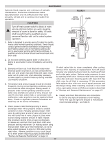
4 Clearances (continued)
Figure 4-1: Minimum Closet Clearances
Model W
FORCE02E 14"
FORCE03E 14"
FORCE04E 16"
FORCE05E 19"
FORCE06E 22"
FORCE07E 25"
FORCE08E 28"
* Minimum radial clearance around vent pipe and breeching for single-wall metal pipe vent connector. Otherwise,
follow vent connector manufacturer's recommended clearances.
** Additional height required to maintain 6" clearance from all vent connector components. Vent damper may be
installed in vertical or horizontal section of vent connector within reach of vent damper harness.
*** Area of each opening to be 1 sq. inch for each 1000 BTU/hr input - with minimum of 100 sq. inches. Height of
opening should be half of width. 3" minimum dimension for air openings.
Model W
FORCE09E 31"
Figure 4-2: Minimum Alcove Clearances

7
FORCE E
Installation, Operating & Service Manual
109444-03 - 12/19
5 Venting
C. Install Vent Damper
OPEN THE VENT DAMPER CARTON and remove
Installation Instructions. READ INSTALLATION
INSTRUCTIONS THOROUGHLY before
proceeding.
Automatic gas control valve supplied on each
FORCE E boiler provides redundancy referenced
in vent damper Installation Instructions.
Figure 5-1 : Vent Damper Installation
A. Inspect chimney and remove any obstructions
or restric tions. Clean chimney if previously used
for solid or liquid fuel-burning appliances or
fireplaces.
B. Locate blocked vent switch on boiler draft hood.
Verify connections are made.
CAUTION
Do not use one vent damper to control more
than one heating appliance.
!
1. Vent damper must be same size as outlet
of vent supplied with boiler (see Table 1B).
Unpack damper carefully - DO NOT FORCE IT
CLOSED! Forcing damper may damage motor
and void warranty.
Insert pilot vent plug into gate and fold over
tabs.
1. Type B or Type L gas vent. Install in
accordance with manufacturer's installation
instructions.
2. Masonry or metal chimney. Build and install
in accordance with local building codes; or
local authority having jurisdiction; or Standard
for Chimneys, Fireplaces, Vents, and Solid
Fuel Burning Appliances, NFPA 211.
Masonry chimney must be lined with
listed clay flue lining or listed chimney
lining system.
3. Single wall metal vent. Allowed by ANSI
Z223.1/NFPA 54 under very restrictive
conditions.
4. Do not use CPVC, PVC, Polypropylene or
any other non-metallic vent pipe. Do not
use cellular core PVC (ASTM F891), cellular
core CPVC, or Radel
®
(polyphenolsulfone).
5. Do not cover non-metallic vent pipe and
fittings with thermal insulation.
2. Mount the vent damper assembly onto draft
hood. (Refer to Figure 5-1 and to instructions
packed with vent damper for specific
instructions). Do not modify either draft hood or
vent damper.
NOTICE: Provide adequate clearance for
servicing.
3. Locate vent damper position indicating means
to be visible following installation.
4. Plug factory harness vent damper connector
into damper motor polarized receptacle.
WARNING
Do not alter draft hood or place any obstruction
or non listed damper in breeching or vent
system. Flue gas spillage and carbon monoxide
production can occur.
!
D. Install vent system in accordance with "Venting
of Appliances" of the National Fuel Gas Code,
ANSI Z223.1/NFPA 54, or applicable provisions
of local building codes. The FORCE E boiler is a
Category I, draft hood equipped appliance with
vent damper.

8
FORCE E
Installation, Operating & Service Manual
109444-03 - 12/19
5 Venting (continued)
E. Install Vent Piping
1. Install vent piping from vent damper outlet
to chimney.
2. Vent pipes serving appliances vented by
natural draft shall not be connected into
any portion of mechanical draft systems
operating under positive pressure.
3. Do not connect into same flue of chimney
serving an open fireplace.
4. Vent pipe to chimney must not be smaller
than outlet on draft diverter or vent damper.
Arrange venting system so boiler is
served by vent damper device.
Exception: National Fuel Gas Code,
ANSI Z223.1/NFPA 54, and allow vent
downsizing when vent size
determined by their Vent Sizing
Tables is smaller than draft diverter
outlet/vent damper. These codes
require all of following:
a. Total vent height (H) is at least
10 ft;
b. Vent not reduced more than one
table size;
and
DANGER
Inspect existing chimney before installing
boiler. Look for corrosion holes. Failure to clean
chimney or replace corroded pipe or tile lining
will cause severe injury or death.
!
Figure 5-2 : Vent Damper Position Indicator
c. Draft diverter outlet/vent damper
is greater than 4 in. in
diameter.
5. Vent pipe should have greatest possible
initial rise above draft diverter consistent
with head room available and required
clearance from adjacent combustible building
structure. Vent pipe should be installed above
bottom of chimney to prevent blockage.
6. Slope vent pipe upward from draft diverter to
vent terminal not less than 1/4" per foot.
7. Support horizontal portions of venting system
to prevent sagging. Use pipe straps, brackets
or hangers spaced 4 ft. or less.
8. Vent pipe must be inserted into but not
beyond inside wall of chimney liner. Seal tight
between vent pipe and chimney.
F. Install vent termination (Masonry chimney and
single wall metal pipe)
1. Termination shall extend at least 5 ft.
in vertical height above highest connected
appliance vent outlet.
2. Termination shall extend at least 3 ft. (2 ft. for
single wall metal pipe) above roof penetration
and at least 2 ft. above any portion of building
within horizontal distance of 10 ft.
G. Install vent termination: (Gas Vent)
1. Termination shall extend at least 5 ft.
in vertical height above highest connected
appliance vent outlet.
2. For terminations located at least 8 ft. from
vertical wall or similar obstruction, termination
shall extend above roof in accordance with
Figure 5-3.
3. For terminations located less than 8 ft. from
vertical wall or similar obstruction, termination
shall extend at least 2 ft. above roof
penetration and at least 2 ft. above any
portion of building within horizontal distance
of 10 ft.
4. Termination shall be at least 3 ft. above forced
air inlet located within 10 ft.

9
FORCE E
Installation, Operating & Service Manual
109444-03 - 12/19
5 Venting (continued)
Figure 5-3 : Termination Location for Gas Vent
Roof Slope Heights
Roof Slope ft.
Flat to 6/12 1.0
Over 6/12 to 7/12 1.25
Over 7/12 to 8/12 1.5
Over 8/12 to 9/12 2.0
Over 9/12 to 10/12 2.5
Over 10/12 to 11/12 3.25
Over 11/12 to 12/12 4.0
Over 12/12 to 14/12 5.0
Over 14/12 to 16/12 6.0
Over 16/12 to 18/12 7.0
Over 18/12 t 20/12 7.5
Over 20/12 to 21/12 8.0

10
FORCE E
Installation, Operating & Service Manual
109444-03 - 12/19
WARNING
Failure to properly pipe boiler may result in
improper operation and damage to boiler or
building.
A. Design and install boiler and system piping to
prevent oxygen contamination of boiler water.
Oxygen contamination sources are system leaks
requiring addition of makeup water, fittings,
and oxygen permeable materials in distribution
system. Eliminate oxygen contamination by
repairing system leaks, repairing fittings, and
using non-permeable materials in distribution
system.
B. Install circulator with flanges, gaskets and bolts
provided.
Figure 6-1: Standard Near Boiler Piping
!
6 Water Piping
WARNING
Safety relief valve discharge piping must be
piped near floor to eliminate potential of severe
burns. Do not pipe in any shut-off valves
between:
1. Safety relief valve and boiler
2. Safety relief valve and discharge
Union may be installed in safety relief valve
piping.
!
C. Install safety relief valve. See Figure 6-1 and 6-2.
Safety relief valve must be installed with spindle in
vertical position.
D. Connect system supply and return piping to
boiler. Refer to Figures 6-3 and 6-4. Also consult
Residential Hydronic Heating Installation and
Design I=B=R Guide. Maintain minimum ½ inch
clearance from hot water piping to combustible
materials.
E. If necessary, supply and return may be connected
to right side of boiler by removing 1-1/4" plugs
from right side of block (under knockouts in
jacket).
NOTICE: Both supply and return connections must
be made on same side of boiler.
F. If boiler is used in connection with refrigeration
system, See Appendix: "Combination
Refrigeration/Heating System".
G. Use a system bypass if boiler is to be operated in
a system which has a large volume or excessive
radiation where low boiler water temperatures may
be encountered (i.e. converted gravity circulation
system, etc.). (See Appendix "Low Return Water
Temperatures").
H. Perform a long term pressure test of hydronic
system, isolate boiler to avoid a pressure loss due
to escape of air trapped in boiler.
To perform a long term pressure test including the
boiler, ALL trapped air must first be removed from
the boiler.
A loss of pressure during such a test, with no
visible water leakage, is an indication that the
boiler contained trapped air.
Safety
Relief
Valve
Right Side
Drain
Return
Temperature
& Pressure
Gauge
Figure 6-2: Alternate Near Boiler Piping

11
FORCE E
Installation, Operating & Service Manual
109444-03 - 12/19
Figure 6-3: Recommended Water Piping Direct Connection System (left side)
6 Water Piping (continued)
At least 18"
of straight pipe
for conventional
air separator
To
System
To
System
Optional Circulator Zone
Controlled System
Optional Zone Valve
Controlled System
System
Circulator
System
Zone
Valves
Zone Circulators
Full Port
Isolation
Valves
Flow Check
From System
Full Port
Isolation
Valves
Drain Valve
Safety Relief Valve
Pipe within 6"
of floor or drain
Drain Valve
IWH
Return
IWH
Supply
Indirect Water Heater
(IWH)
Air Separator
& Air Vent
Expansion
Tank
Backflow
Preventer
Fill
Valve
Cold
Water
Return
Full Port
Isolation
Valves
Unions
Flow Check
IWH Circulator
Full Port
Isolation
Valve
Unions
Full Port
Isolation
Valve

12
FORCE E
Installation, Operating & Service Manual
109444-03 - 12/19
6 Water Piping (continued)
'C'
'B'
'A'
To
System
To
System
Optional Circulator Zone
Controlled System
Optional Zone Valve
Controlled System
System
Circulator
System
Zone
Valves
Zone Circulators
Full Port
Isolation
Valves
Flow Check
From System
Full Port
Isolation
Valves
Drain Valve
Safety Relief Valve
Pipe within 6"
of floor or drain
Drain Valve
IWH
Return
IWH
Supply
Indirect Water Heater
(IWH)
Air Separator
& Air Vent
Expansion
Tank
Backflow
Preventer
Fill
Valve
Cold
Water
Return
Full Port
Isolation
Valves
Unions
Flow Check
IWH Circulator
Full Port
Isolation
Valve
Unions
Full Port
Isolation
Valve
A. At least eight pipe diameters upstream of boiler return tee.
B. No further apart than 12" (~30cm) or four pipe diameters, whichever is smaller.
C. At least 18" (~46cm) of straight pipe for
Conventional
Air Scoop.
Circulator
Figure 6-4: Recommended Piping for Primary/Secondary System (left side)

13
FORCE E
Installation, Operating & Service Manual
109444-03 - 12/19
A. Size gas piping. Design system to provide
adequate gas supply to boiler. Consider these
factors:
1. Allowable pressure drop from point of delivery
to boiler. Maximum allowable system pressure
is ½ psig. Minimum gas valve inlet pressure is
listed on rating label. See Table 7-1.
Figure 7-2: Gas Piping
7 Gas Piping
Natural
Gas
Inlet Min
(in. wc.)
Inlet Max
(in. wc.)
Manifold
(in. wc.)
All Sizes 4.5 14.0 3.5
LP
Inlet Min
(in. wc.)
Inlet Max
(in. wc.)
Manifold
(in. wc.)
All Sizes 11.0 14.0 10.0
Table 7-1: Gas Pressure
Figure 7-3: Gas Manifold and Control Assembly
2. Maximum gas demand. Consider existing and
expected future gas utilization equipment (i.e.
water heater, cooking equipment).
B. Connect boiler to gas supply system.
1. Use methods and materials in accordance with
local plumbing codes and requirements of gas
supplier. In absence of such requirements,
follow National Fuel Gas Code, ANSI Z223.1/
NFPA 54.
2. Use thread compounds (pipe dope) resistant to
action of liquefied petroleum gas.
3. Install sediment trap, ground-joint union and
manual shut-off valve upstream of boiler gas
control valve. See Figure 7-2 (within 6 ft. of
boiler).
4. All above ground gas piping upstream from
manual shut-off valve must be electrically
continuous and bonded to a grounding
electrode. Do not use gas piping as grounding
electrode. Refer to National Electrical Code,
ANSI/NFPA 70.
C. Pressure test. Boiler and its gas connection must
be leak tested before placing boiler in operation.
See Startup and Checkout Section E and H " Gas
Leak Test" for guidance.

14
FORCE E
Installation, Operating & Service Manual
109444-03 - 12/19
8 Electrical
A. Install wiring so boiler is electrically bonded
to ground in accordance with requirements of
authority having jurisdiction, or in absence of such
requirements, with the National Electrical Code,
ANSI/NFPA 70.
B. Install thermostat. Locate on inside wall
approximately 4 feet above floor. Do not install on
outside wall, near fireplace, or where influenced
by drafts or restricted air flow, hot or cold water
pipes, lighting fixtures, television, or sunlight.
Allow free air movement by avoiding placement of
furniture near thermostat.
C. Wire boiler. Boiler is rated for 120 VAC, 60 HZ,
less than 12 A. A separate electrical circuit must
be run from the main electrical service with an
over-current device/disconnect in the circuit. A
service switch is recommended and may be
required by some local jurisdictions. Connect to
L1, L2, and green ground wires. See Figures 8-1
and 8-2.
D. For installations using zone valves provide
separate transformer for zone valve wiring.
Consult zone valve manufacturer for assistance.
CAUTION
This boiler contains controls which may cause
the boiler to shut down and not restart without
service. If damage due to frozen pipes is a
possibility, the heating system should not be
left unattended in cold weather; or appropriate
safeguards and alarms should be installed on
the heating system to prevent damage if the
boiler is inoperative.
!
WARNING
Electrical Shock Hazard. Wiring errors can
cause improper or dangerous operation. Verify
proper operation after installation.
!

15
FORCE E
Installation, Operating & Service Manual
109444-03 - 12/19
Figure 8-1: Wiring Connection Diagram
8 Electrical (continued)

16
FORCE E
Installation, Operating & Service Manual
109444-03 - 12/19
Figure 8-2: Schematic Ladder Diagram
8 Electrical (continued)

17
FORCE E
Installation, Operating & Service Manual
109444-03 - 12/19
A. Visual Main Burner Check
Inspect burners for dislodgement during
shipment. Rear of burners should be in vertical
slots in rear of burner tray and front of burners
should be seated completely on orifices.
B. Initial LWCO Test
Before filling boiler with water, turn on power to
boiler and set thermostat to call for heat. Both
the green "ACTIVE LED" and amber "LOW WATER"
LED should illuminate. Burner should not fire.
WARNING
If the burner fires with no water at probe,
immediately shut down power to boiler and
contact customer service for assistance.
C. Fill boiler with water
1. Proceed to fill boiler with water. When water
reaches temp/LWCO sensor "LOW WATER"
LED will turn off and burner will fire.
2. Turn off power to boiler and finish filling
system.
D. Purge air from system
1. Fill entire heating system with water and
vent air from boiler, radiators and system,
one zone at a time.
2. Isolate boiler by closing isolation valves.
3. Isolate all circuits by closing zone valves
or turning off zone circulators.
4. Attach hose to drain valve located
on return piping (see Figure 6-3 and 6-4).
Note-Terminate hose in five gallon bucket,
at a suitable floor drain, or outdoor area).
5. Starting with one circuit, open zone valve or
start circulator.
6. Open drain valve.
7. Open fill valve.
8. Allow water to flow through system until
discharge from hose is bubble free for 30
seconds.
9. Open zone valve or start circulator to
second zone to be purged, then close
first. Repeat this step until all zones have
been purged, but always have one zone
open. At completion, open all zone valves.
10. Close hose bib, open boiler isolation
valve, continue filling system until
pressure gauge reads 12 psi.
Close fill valve. (Note - If make-up water
line is equipped with pressure reducing
valve, system will automatically fill to 12
psi).
11. Remove hose from drain valve.
E. Perform gas leak test upstream of boiler shutoff
valve.
1. Protect boiler gas valve.
a. For all testing over ½ psig, boiler
and manual shutoff valve must be
disconnected from gas supply piping.
b. For testing at ½ psig or less, isolate
boiler from gas supply piping by closing
boiler manual shutoff valve.
2. Locate leaks using listed combustible
gas detector, a noncorrosive leak detection
fluid or other listed leak detection method.
3. Tighten appropriate pipe connections.
9 System Start-Up and Checkout
!
DANGER
Do not use matches, candles, open flames, or
other ignition sources.
!

18
FORCE E
Installation, Operating & Service Manual
109444-03 - 12/19
Figure 9-1: Operating Instructions
9 System Start-Up and Checkout (continued)

19
FORCE E
Installation, Operating & Service Manual
109444-03 - 12/19
2. PURGE AIR FROM GAS PIPING by loosening
(or removing) “Inlet Pressure Tap” plug on gas
valve (See Figure 9-2). Tighten (or replace)
plug when you start to smell gas. Adequate
ventilation must be provided and no smoking
or open flame permitted.
3. Locate and address leaks using listed
combustible gas detector,a non corrosive leak
detection fluid or other listed leak
detection method.
a. Check pipe fittings up to inlet of gas valve
b. Check piping between gas valve and
orifices (after boiler is operating).
c. Check piping between gas valve and pilot
(after boiler is operating).
4. Tighten appropriate pipe connections.
I. Check pilot burner flame.
Natural Gas Only. Pilot produces single flame.
Flame should be steady medium hard blue
enveloping 3/8 to 1/2 inch of igniter-sensor tip.
See Figure 9-3.
9 System Start-Up and Checkout (continued)
4. Turn "OFF" the electric switch to boiler.
G. Start boiler according to "Operating Instructions"
in Figure 9-1.
H. Perform gas leak test downstream of boiler
manual shutoff valve.
1. Open manual shutoff valve.
F. Perform limit check
1. Ensure gas to boiler is off
2. Set ROOM THERMOSTAT to lowest setting.
3. If limits are functioning properly (LWCO, flame
rollout switch, blocked vent switch, damper),
boiler should spark. If boiler does not spark,
see Section 14 "Troubleshooting" for guidance.
Figure 9-3: Pilot Burner Flame (NG Only)
Figure 9-4: Pilot Burner Flame (LP Only)
Figure 9-2: Top View of Gas Valves
LP Gas Only. Pilot burner produces three (3)
flames. The center flame should be steady,
medium hard blue enveloping 3/8 to 1/2 inch of
sending probe. See Figure 9-4.

20
FORCE E
Installation, Operating & Service Manual
109444-03 - 12/19
9 System Start-Up and Checkout (continued)
CAUTION
Avoid operating boiler in an environment where
saw dust, loose insulation fibers, dry wall dust,
etc. are present. If boiler is operated under
these conditions, burner interior and ports
must be cleaned and inspected daily to ensure
proper operation.
!
Figure 9-5: Main Burner Flame
J. Check Main Burner Flame (see Figure 9-5)
1. NORMAL FLAME:
a. Clearly defined inner cone with no yellow
tipping.
b. Orange-yellow streaks caused by dust
should not be confused with true yellow
tipping.
2. ABNORMAL FLAME (if found, check inlet and
outlet gas pressure. Procedure found in
following steps):
a. Overfired - large flame
b. Underfired - small flames
c. Lack of primary air - yellow tipping on
flames.
K. Check gas Inlet pressure
1. While boiler and all other gas appliances
are not firing, gas inlet pressure should not
exceed ½ psig.
2. While boiler and all other gas appliances
are firing, gas inlet pressure must be
between minimum and maximum shown
on rating label.
L. Check gas outlet (manifold) pressure
1. Install manometer on 1/8" outlet pressure
tap on gas valve (see Figure 9-2). Use
of shutoff valve between manometer and gas
valve can prevent pressure surge that blows
out manometer fluid.
2. Adjust regulator on gas valve so manifold
pressure matches values listed on rating label.
3. Turning regulator adjustment screw
clockwise () increases pressure.
4. Turning regulator adjustment screw
counterclockwise () decreases pressure.
M. Check gas input rate to boiler
1. When checking rate, ensure all other
appliances connected to same meter as
boiler are off.
2. Input ratings shown on boiler rating label
can be used for elevations up to 2,000 ft. For
elevations 2,000 ft. or higher, reduce input
rate to 4 percent per 1,000 ft. above sea level.
Do not install at elevations above 12,000 ft.
See Table below.
Input (MBH)
Boiler
Mode
Rating
Label
5,000 ft. 7,000 ft. 10,000 ft.
FORCE02E 38 30.5 27.5 23.0
FORCE03E 68 54.5 49.0 41.0
FORCE04E 102 81.5 73.5 61.0
FORCE05E 136 109 98.0 81.5
FORCE06E 170 136 122.5 102.0
FORCE07E 204 163 147.0 122.5
FORCE08E 238 190.5 171.5 143.0
FORCE09E 272 217.5 196.0 163.0
N. Measure carbon monoxide (CO) level in vent after
5 minutes of main burner operation. CO should
not exceed 400ppm air free.
O. Check vent damper operation.
Vent damper must be in open position when
/