
I—SHIP PING AND PACK ING LIST
Package 1 of 1 contains:
1—Supply Air Cover Panel
1—Return Air Cover Panel
1—Supply Panel w/ Duct Opening
1—Return Panel w/ Duct Opening
1—Return Filter Access Panel
1—Bag assembly containing:
1—Limit Switch
(Used on Gas Heat Models Only - R4GN Series &
R6GP 120*-235C )
2—Clips (304260)
6—Screws 10 x ½ x 16 Hex Tec
Check contents for shipping damage. Contact the last carrier
immediately if any shipping damage is found.
II—AP PLI CA TION
This kit provides a means of converting downflow discharge rooftop
equipment to horizontal discharge by supplying cover panels for
downflow air openings and replacement panels for side air openings.
Notice to Installer - (For R4GN Series & R6GP 120*-235C Models
Only) Upper Main Air Temperature Limit must
be replaced with Part
#626485 when installing this kit. See steps 8-13 for installation.
III—IN STAL LA TION
1—Remove existing supply and return access panels of unit to
provide for horizontal air openings. Retain screws to be used
later.
2—Place supply air cover panel (insulated side down) over flanges of
supply air opening in bottom of unit. Fasten cover panel to
flanges and, using holes in cover as a guide, drill holes in opening
flanges and attach cover with screws provided.
3—Place return air cover panel (insulated side down) over flanges of
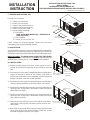
return air opening and attach as per step 1 above. See Figure 1.
4—Install supply panel with duct opening to unit horizontal supply air
opening of unit. Using holes in the bottom of panel and secure
with screws from Step 1.
5—Install return panel with duct opening to unit horizontal return air
opening of unit. Using holes in the bottom of panel and secure
with screws from Step 1.
6—Take the two clips and place one on each side of return panel
and using a screw from the unit posts to secure so tab is over
return panel.
7—Attach filter access panel, above return air opening, flush with top
panel. With panel firmly against flanges, install two screws
provided and tighten securely. See Figure 3.
INSTALLATION
INSTRUCTION
30
16.5
16.5
30
FIGURE 1
FILTERS
FIGURE 3
SUPPLY
RETURN
SUP PLY AIR
COVER PANEL
RE TURN AIR
COVER PANEL
COVER PANEL
UNIT BASE
LIPS UNDER BACK
OF OPENING
FILTER ACCESS
PANEL
FORM# 612A-0411 (612A-1110)
TWO CLIPS TO HOLD
PANEL IN PLACE.
FIGURE 2
RE TURN PANEL
W/ DUCT OPENING
SUPPLY PANEL W/
DUCT OPENING
FILTER ACCESS
PANEL
INSTALLATION INSTRUCTIONS FOR
547872 / 547881
HORIZONTAL AIR DISCHARGE KIT
USED WITH R4GN/P4SN/P6SP/Q6SP 090-120 & R6GP 120 UNITS

Note: For Gas Heat Models Only.
8—Disconnect all electrical power to unit before replacing limit control.
9—Remove blower access panel and locate upper main air limit on interior divider panel above blower outlet duct.
10—Remove screws securing upper main air limit in place.
WARNING!
MARK ALL WIRES AND NOTE TERMINAL ORIENTATION BEFORE REMOVAL OF WIRING OR
TRANSFER WIRES IMMEDIATELY TO NEW MAIN AIR LIMIT TO ENSURE PROPER OPERATION OF UNIT.
Combustion Blower Motor Switch Lead (Single Red) - Terminal #1
Blower Limit Relay Leads (Dual Red) - Terminal #2
Upper to Lower Main Air Limit Lead (Single Red) - Terminal #3
11—Install new upper main air limit, Part # 626485 and secure using screws from Step 10.
12—Check all terminals for proper connections.
13—Replace blower access panel and reconnect electrical power to unit.
NEIHSR07
INSTALLATION
INSTRUCTION
INSTALLATION INSTRUCTIONS FOR
547872 / 547881
HORIZONTAL AIR DISCHARGE KIT
USED WITH R4GN/P4SN/P6SP/Q6SP 090-120 & R6GP 120 UNITS
SUPERSEDES 11-29-10
APRIL 15, 2011
© Nortek Global HVAC
, LLC 2015. All Rights Reserved.
-
 1
1
-
 2
2


Unbranded Q6SP Installation guide
- Type
- Installation guide
- This manual is also suitable for
Ask a question and I''ll find the answer in the document
Finding information in a document is now easier with AI
Related papers
-
Unbranded R6GP Installation guide
-
-
-
Reznor R6GP Installation guide
-
-
-
-
-
-
Other documents
-
-
-
-
-
-
Mammoth Natural Gas, High-Altitude Conversion Kit Installation guide
-
-
-
SGM TLD·612A User manual
-
Reznor P6SP Installation guide