LA 90L / LA 180L
Operating instructions
en

A
3a
3b
4
5
6
7
8
LA 180L

1d
1c
1a
1b
2b
2a
B
LA 180 L
LA 90 L
C
A1

E1 E2
D1
90°
> 2,8m
D2
1
1
2
E3
1
2
D
D
X
Y
F
± 5°
> 11
3
1
3
ft
Y
Y 1m

1
A
G4
2
B
1
A
2
B
1
A
2
B
2
3
S
> 5 m
> 16
3
1
3
G1
D3
2,8m
G5
G3G2
11

Operating instructions
The STABILA-LA90L / LA 180L instruments are easy-to-use multi-line lasers.
They are self-levelling within the range of ± 5° and enable the user to level quickly
and precisely. The vertically and horizontally projected laser lines provide exact
alignment / working. The LA 180L has a motorised ne adjustment facility for 90°
angle positioning. The pulsed laser lines allow the instrument to operate over long
distances using a special line receiver (-> see Operating Manual, Line Receiver)
We have endeavoured to explain the unit‘s handling and functioning in as clear
and comprehensible manner as possible. If you have any technical questions,
you can contact us at any time. Telephone number:
0049 / 63 46 / 3 09 - 0
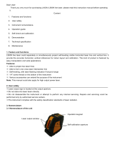
Main components
(1a)
(1b)
(1c)
(1d)
(2)
(2a)
(2b)
(3a)
(5)
(6)
(7)
(8)
(9)
On/o button
Button: automatic levelling on / o - manual mode
Button : horizontal line on/o
Button : vertical lines on/o
LEDs for displaying:
LED green : Operating mode ON or READY / OK
LED red : battery voltage and overheat
Exit aperture for the horizontal and vertical laser lines
Adjusting screw: precision adjustment to alignment of vertical laser lines
Shock protection
5/8“ threaded connector for tripod
REC 410 Line RF receiver
Only LA-180L:
Recycling programme for our EU customers:
In accordance with the WEEE regulations, STABILA provides a disposal
programme for electronic products at the end of their service life.
For more details, please contact: 0049 / 6346 / 309 - 0
(1) Selector switch:
(3b)Exit aperture for vertical beam
(4) Battery compartment
Upper part
A
A1
1.800.869.7460 U.S. and Canada
en

Main applications:
The LA90L / LA 180L can be used in 2 operating modes:
Operating modes
1. as a self-levelling line laser
- for horizontal levelling
- for vertical alignments
- for plumb-lining
- for constructing 90° angles
2. as a laser instrument for marking
applications without the levelling function.
Operating mode with self-levelling
The instrument is turned on with the on/o switch (1a). Vertical laser lines and
a plumb point appear aer switching on. However, if only the horizontal line
was on just prior to the last time the instrument was switched o, the horizontal
laser line will appear when the instrument is turned on.
The laser is automatically aligning itself all the while the laser lines are flashing
( < 15 seconds). Flashing frequency: slowly
Commissioning
(1a)
NB:
In Class 2 laser equipment, your eyes are normally
protected from accidental, short-term exposure
to the laser beam by the lid-closing reflex and/or
the reflex reaction to turn one‘s head. If a laser beam should
encounter your eye, you should consciously close your
eyes and immediately move your head out of the beam.
Do not look directly into the direct or reflected beam.
The laser goggles enclosed with these units are not safety
goggles. They are designed to make the laser beam easier
to see. The use of operating and adjustment equipment
other than that indicated here or the use of other pro-
cedures can lead to dangerous exposure to radiation.
Alterations ( manipulation ) to the laser instrument by
the customer is not permitted. These Operating Instructions must be retained
and passed to the next user of the laser instrument.
Do not let the unit fall into children‘s hands !
Do not direct the laser beam at people.
LASER RADIATION
DO NOT STARE
INTO BEAM
IEC 60825-1:2007
P0 < 1 mW
λ = 630 - 660 nm
Beam divergence < 180°
Beam divergence <1.5mrad

Plumb-lining:
As described in “Setting the Type of Line“, at least 2 vertical lines at an angle
of 90° to each other are switched on. These two lines intersect above the plumb
point below so that the plumb points can be transferred from the floor to the
ceiling.
Constructing 90° angles:
As described in “Setting the Type of Line“, at least 2 vertical lines at an angle of
90° to each other are switched on.. This 90° angle can, for instance, be used to
check 90° angles or align items at a right angle to each other.
The ne adjustment facility described below makes this work signicantly
easier.
If the inclination is too great the laser and the LED display flash (green) !
laser beam flashing-> The unit is inclined too much
+ is outside the self-levelling range
+ the laser cannot level itself automatically
Button (1d): dierent vertical laser lines can be switched on / o in succession.
The plumb-line point is also switched on / o at the same time. All the vertical
laser lines can only be switched o if the horizontal laser line is switched on.
If button 1d is pressed again, the vertical laser lines are switched on again in
their last conguration. Single vertical laser lines can be used, for example, for
marking out vertical planes or aligning vertical building components or members.
Setting the type of line:
Button (1c): switches the horizontal laser line on/o. The horizontal laser line
can only be switched o if at least one vertical laser line is switched on.
The horizontal laser line can be used, for example, for levelling over long
distances or for the horizontal alignment of building components and members.
C
B
(1d)
(1c)

Fine adjustment
Using the adjusting screw, the upper part can be rotated through ± 5° around
its vertical axis, enabling a vertical laser line to be aligned precisely with a
reference line. With the LA-180L, the ne adjustment procedure can also be
undertaken using the receiver.
Vertical check
1. Vertical accuracy check
You must create a reference to perform this test. Fasten a plumbline near to the
wall. The laser unit should now be set up in front of this reference
mark(distance Y) and the vertical laser line compared with it.
The discrepancy between the centre of the laser line of
the multi-line laser and the reference mark should be no
greater than 1 mm / 3/64“ from the reference mark over
a length of 2.8 m / 11 . This vertical check should be
undertaken separately for all vertical laser lines.
2. Checking plumb-lining
1. Set up the instrument
2. Switch on the instrument - button (1a)
3. Switch on the vertical laser lines - button (1d)
4. Place the laser so that its down beam is aligned over
a reference mark on the floor.
5. Mark the position of the laser cross on the ceiling.
6. Rotate the laser through 180° and realign the laser beam on
the reference mark on the floor.
7. Mark the position of the laser cross on the ceiling.
8. Measure the dierences in the x and y directions between the two marks on
the ceiling. The dierence is twice the actual error. In each case the dierence
may not be greater than 4 mm in 6 m / 5/64“ in 10 .
Operating mode without levelling function.
Button (1b): the levelling function is switched o.
In this mode the laser lines flashes. Flashing frequency: rapid
Checking the calibration
The LA90L / LA180L multi-line laser was designed for use on construction
sites and was perfectly adjusted when it le our factory. As with any precision
instrument, however, its calibration must be regularly checked. The unit should
be checked before starting any new tasks, particularly when the unit has been
exposed to strong vibrations. Aer an impact, the unit should be checked
throughout its whole self-levelling range.
F
D1
D2
D3
E1
E2
1 mm
3/64“

A
B
C
D
E
A
E
I2
L = 10m
H3
H2
A
B
C
D
L = 10m
H1
A
B
C
I3
I1
16‘5“
32‘10“
16‘5“
16‘5“
16‘5“
16‘5“
16‘5“
32‘10“

1. Choose a room which is at least 10 m ( 32‘10“ ) long.
At one end mark point „A“ on the floor.
2. Align the laser with its plumb-line beam directly over point „A“.
Ensure that laser line 1 can be seen at the opposite end of the room.
3. At about the middle of the room mark point „B“ on the floor.
4. Mark point „C“ on the opposite wall or on the floor.
5. Move the LA-90L ( LA-180L ) to point B and realign laser line 1 on point „C“.
6. Mark position „D“ of the right-angle laser line 2 on the floor.
LA-90L, LA-180L: checking 90° angle I
3. Checking the angular accuracy of the vertical lines:
checking the 90° angle of the vertical lines.
Note:
In order to guarantee accuracy, the distance of „A“ to „B“, „B“ to „C“ and
„B“ to „D“ should be equal.
7. Rotate the LA-90L ( LA-180L ) through 90° so that laser line 1 is aligned
with point „D“.
8. Mark position „E“ of the right-angle laser line 2 as close as possible to
point „A“ on the floor.
9. Measure the distance between points „A“ and „E“.
Only LA-180L:
90° angle II is checked using the same method but using only laser lines 2 and 3.
1
3
2
II
I
H1
H2
H3
≤ 2,0 mm
≤ 4,0 mm
32‘10“
65‘8“
Length of the room or distance
between points „A“ and „C“.
Each of the 90° angles are accurately
calibrated if the distance between
points „A“ and „E“ is as follows:
10 m
20 m
≤ 5/64“
≤ 5/32“

Horizontal checking
1. Horizontal checking - Line level
Two parallel wall surfaces at least 5m /16‘5“ apart are required for the horizontal check.
Measure the vertical distance
between point 1 and point 3.
The dierence must not be
greater than:
1. Place the LA90L / LA180L on a smooth surface or on a tripod as close
as possible to wall A and with the front side pointing towards the wall
2. Switch the unit on - button (1a)
3. Switch on the horizontal laser line - button (1c)
4. Switch on the vertical laser lines - button (1d)
5. Mark the position of the visible laser line cross on the wall A (point 1).
6. Turn the complete unit 180° without altering the height of the laser.
7. Mark the position of the visible laser line cross on the wall B (point 2).
8. Now move the unit directly in front of wall B.
9. Set the unit‘s height so that the laser dot‘s height matches that of point 2.
10. Without changing the height of the laser, rotate it 180° to place the beam
near the mark on the rst wall (step 3 / point 1 ).
2. Horizontal checking - inclination of the laser line
Check the laser line for inclination and perfectly straight projection
1. Mark three points (1, 2 and 3) on the floor at a distance of 5 m /16’5”
from each other; the points must be in a perfectly straight line.
2. Position the laser at distance S = 5 m / 16‘5“ from the line and exactly in
front of the middle point you marked = position X
3. Switch the unit on - button (1a)
4. Switch on the horizontal laser line - button (1c)
5. Measure the height of the laser line at the points. Measurements X1 - X3
6. Reposition the instrument.
7. Position the laser at distance S = 5 m / 16‘5“ from the line and exactly in
front of the middle point you marked = position Y
8. Measure the height of the laser line at the points. Measurements Y1-Y3
Δ1 = X1 - Y1 Δ2 = X2 - Y2 Δ3 = X3 - Y3
When calculating, always take
note of the preceding prex !
I1
I2
I3
G1
G2
G3
G4
G5
(1a)
(1c)
(1d)
S Maximum permissible dierence
5 m 16‘5“ 1,0 mm 5/128“
10 m 32’10” 2,0 mm 5/64“
15 m 49’3” 3,0 mm 1/8“
20 m 65’8” 4,0 mm 5/32“
L Δ ges 1 or Δ ges 2
5 m 16‘5“ 2,0 mm 5/64“
7,5 m 24’8” 3,0 mm 1/8“
10 m 32’10” 4,0 mm 5/32“
Δ ges 1 = Δ 1 - Δ 2 < ± 2mm ± 5/64“
Δ ges 3 = Δ 3 - Δ 2 < ± 2mm ± 5/64“

or STABILA battery unit
1
2
3
4 x 1,5 V
mono cells alkaline,
size D, LR 20
Replacing the batteries
Open the battery compartment (4) by moving it in the direction of the arrow.
Insert new batteries following the instructions in the battery compartment.
Tip:
Remove the batteries if the
unit will not be used for a
long period !
Only LA-180L:
Registering the REC 410 Line RF receiver with the laser transmitter :
1. Switch off the laser transmitter (button 1a)
2. Press and hold down buttons (1c) and (1d).
3. Switch the unit on - button (1a)
4. The laser transmitter is in registration mode.
The LEDs (red and green) flash alternately.
5. Press the button “automatic precision alignment“ (d) on
the REC 410 Line RF receiver.
6. The red and green LEDs on the laser transmitter will flash 3 times for 3 seconds:
-> Registration was successfully completed.
1. Horizontal checking - Line level
Two parallel wall surfaces at least 5m /16‘5“ apart are required for the horizontal check.
(1a)
(1d)
(d)
(1c)

Do not store the laser when wet. Dry
the laser and case before putting
the laser away.
Do not submerge the laser.
Do not unscrew !
Operating status display and error messages via the LEDs
Illuminated green LED
-> laser in operation
Illuminated green LED
+ laser beam flashing
-> The laser levels itself automatically
Flashing green LED
+ laser beam flashing
-> The unit is inclined too much
+ is outside the self-levelling range
+ the laser cannot level itself automatically
Illuminated red LED
-> laser in operation
-> battery voltage very low
-> battery replacement required imminently
Illuminated red LED
+ laser beam flashing
-> The laser levels itself automatically
-> Battery voltage very low
-> Battery replacement required imminently
Flashing red LED
+ laser beam flashing
-> Battery voltage very low
-> The unit is inclined too much
+ is outside the self-levelling range
+ the laser cannot level itself automatically
-> The temperature in the unit is over 50°C / 122°F
-> The laser diodes have been switched o to protect
against overheating
-> Place the unit in the shade to be able to continue
working.
-> The laser is not working
Only LA-180L:
The LEDS flash red
+ green
+ laser cannot be seen
The LEDS flash red +
green alternately
The LEDS flash 3 x during
a period of 3 seconds
The appliance is in registration mode
The registration was successful

Care and maintenance
• Dirty lens glass on the beam emitter detracts from the quality of the beam.
It should be cleaned with a so cloth.
• Clean the laser unit with a damp cloth. Do not spray or immerse the unit!
Do not use solvents or thinners!
The LA90L / LA180L multi-line laser must be handled carefully, in the same
way as any precision optical instrument.
Guarantee terms and conditions
Stabila provides a guarantee against deciencies and faults in the assured charac-
teristics because of material or manufacturing faults for a period of 24 months from
date of purchase. Any faults will be eliminated at Stabila‘s own discretion either
by repairing or replacing the unit. Stabila accepts no further claims.
No liability is accepted for any faults due to inappropriate treatment (e.g. damage
caused by the unit falling, operation with the wrong voltage or type of current,
use of unsuitable current supply sources) or for any alterations changes made to
the unit by the purchaser or a third party.
Also no claims under guarantee are accepted for natural wear and tear or any
small faults that do not signicantly aect the unit‘s operation.
Any guarantee claims must be made via the dealer on the duly completed
guarantee form (see last page) to be returned with the unit.
Technical data
Laser type: line:
Laser type plumb-line point:
Output:
Self-levelling range:
Levelling accuracy*
Middle of the laser line:
Laser line inclination horizontal:
Laser line inclination vertical :
90° accuracy*
vertical laser lines:
vertical and horizontal laser line:
Plumb-line beam:
Batteries:
Operating life:
Operating temperature range:
Storage temperature range:
* When operated within specied temperature range.
Subject to technical modications.
Red diode laser, pulsed line-laser
wavelength 630- 660 nm
wavelength 650- 660 nm
< 1 mW, Laser Class 2 to IEC 60825-1:2007
± 5°
± 0,07 mm/m
± 0,10 mm/m
± 0,10 mm/m
± 0,20 mm/m
± 0,20 mm/m
± 0,20 mm/m
4 x 1,5 V Monocells alkaline, size D, LR20
approx. 20 hours (alkaline) 4 x 1,5 V
-10 °C to +50 °C / 14°F to + 122°F
-25 °C to +70 °C / - 13°F to + 158°F
This product complies with 21CFR parts 1040.10 and 1040.11.
± 3/32“ over 100
± 1/8“ over 100
± 1/8“ over 100
± 1/4“ over 100
± 1/4“ over 100
± 1/4“ over 100
/