
238-45085-00F REV 5/18
DOUBLE-WALL
INDIRECT-FIRED
WATER HEATER
A Spanish language version of these instructions is available by contacting the
manufacturer listed on the rating plate.
La version espanola de estas instruccions se puede obtener al escribirle a la fábrica
cuyo nombre aparece in la placa de especificaciones.
INSTALLATION/OPERATING MANUAL
WITH PARTS LISTING AND TROUBLESHOOTING GUIDE
For your family’s comfort, safety, and convenience, we
recommend this water heater be installed and serviced by
a plumbing professional.
WARNING
To avoid damage or injury, there
must be no materials stored
against the indirect water heater
and proper care shall be taken to
avoid unnecessary contact
(especially by children) with the
indirect water heater.
Do not store or use
gasoline or other
flammable liquids in
the vicinity of this
water heater or any
other appliance.

2
CONGRATULATIONS!
You have just purchased one of the finest water heaters
on the market today!
This installation, operation, and instruction manual will
explain in detail the installation and maintenance of your
new Indirect water heater. We strongly recommend that
you contact a plumbing professional for the installation of
this water heater.
We require that you carefully read this manual, as well as
the enclosed warranty, and refer to it if questions arise. If
you have any specific questions concerning your
warranty, please consult the plumbing professional from
whom your water heater was purchased. For your
records we recommend that you write the model, serial
number and installation date of your water heater in the
back of this manual.
This manual should be kept with the water heater.
We’re committed to providing you with the finest water
heater made.

3
CAUTION
The maximum boiler water supply temperature to the indirect
heat exchanger must not exceed 240°F (115°C).
NOTICE
Insulation blankets are not required for this water heater. This
water heater meets or exceeds the ASHRAE/IES 90.1b standards
with respect to insulation and standby loss requirements.
TABLE OF CONTENTS
I-
IMPORTANT INFORMATION…………….… 4
II-
SPECIFICATIONS……………………………… 8
III-
GENERAL INFORMATION…………………... 11
IV-
PRE INSTALLATION………………………….. 14
V-
WATER CONNECTIONS……………………… 18
VI-
ELECTRICAL CONNECTIONS……………… 23
VII-
OPERATING INSTRUCTIONS……………….. 26
VIII-
MAINTENANCE………………………………... 29
IX-
TROUBLESHOOTING GUIDE……………….. 32
X-
PARTS LIST……………………………………... 34
XI-
NOTES……………………………………………. 36

4
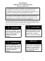
SECTION I
IMPORTANT INFORMATION
-READ CAREFULLY-
The equipment must be installed in accordance with those
installation regulations required in the area where the
installation is to be made. These regulations must be
carefully followed in all cases. Authorities having jurisdiction
shall be consulted before installations are made.
All wiring on water heaters installed in the USA must be in
accordance with the National Electrical Code and/or local
regulations; or in Canada, installed in accordance with the
Canadian Electrical Code and/or local regulations.
The following terms are used throughout this manual to bring
attention to the presence of hazards of various risk levels, or to
important information concerning product life.
DANGER
Indicates an imminently
hazardous situation, which,
if not avoided, will result in
death, serious injury, or
substantial property
damage.
WARNING
Indicates a potentially
hazardous situation, which,
if not avoided, could result
in death, serious injury, or
substantial property
damage.
CAUTION
Indicates a potentially
hazardous situation, which,
if not avoided, may result
in moderate, or minor
injury or property damage.
NOTICE
Indicates special
instructions on installation,
operation or maintenance,
which are important but
not related to personal
injury hazards.

5
Important Info continued-
DANGER
DO NOT store or use gasoline or other flammable,
combustible, or corrosive vapors and/or liquids in the vicinity
of this or any other appliance.
IF YOU SMELL GAS:
DO NOT try to light any appliance.
DO NOT touch any electric switch; do not use any
telephone in your building.
Immediately call your gas supplier from a telephone in
another building. Follow the gas supplier’s instructions.
If you cannot reach your gas supplier, call the fire
department
DO NOT OPERATE THE APPLIANCE UNTIL THE
LEAKAGE IS CORRECTED!
Liquefied petroleum gas/propane gas is heavier than air and
will remain at floor level if there is a leak. Basements, crawl
spaces, closets, and areas below ground level will serve as
pockets for accumulation of leaking gas.
This water heater is supplied with an adjustable thermostat to
control water temperature. Hot water temperatures required
for automatic dishwasher and laundry use can cause scald
burns resulting in serious personal injury and/or death. The
temperature at which injury occurs varies with the person’s
age and the time of exposure. The slower response time of
disabled persons increases the hazards to them. NEVER allow
small children to use a hot water tap or to draw their own
bath water. NEVER leave a child or disabled person
unattended in a bathtub or shower.
To comply with NSF requirements this water heater is to be:
a) Sealed to the floor with sealant, in a smooth and easily
cleanable way, or
b) Installed with an optional leg kit that includes legs
and/or extensions that provide a minimum clearance
of 6” beneath the water heater.

6
Important Info continued-
WARNING
Installation is not complete unless a properly sized/capacity
pressure and temperature relief valve is installed into the side
of the water heater. See the General Information section of this
manual for details.
This water heater contains very hot water under high pressure.
Do not unscrew any pipe fittings or attempt to disconnect any
components of this water heater without positively assuring the
water is cool and has no pressure. Always wear protective
clothing and equipment when installing, starting up, or
servicing this water heater to prevent scald injuries. Do not
rely on the pressure and temperature gauges to determine the
temperature and pressure of the water heater. This water
heater contains components that become very hot. Do not
touch any components unless they are cool.
Improper installation, adjustments, alteration, service or
maintenance can cause property damage, personal injury or
loss of life. Failure to follow all instructions in the proper order
can cause personal injury or death. Read and understand all
instructions, including all those contained in component
manufacturer’s manuals, which are provided with the
appliance before installing, starting-up, operating,
maintaining, or servicing this appliance. Keep this manual and
literature in legible condition and posted near the appliance for
reference by owner and service technician.
This water heater requires regular maintenance and service to
operate safely. Follow the instructions contained in this
manual.
Installation, maintenance, and service must be performed only
by an experienced, skilled, and knowledgeable installer or
service agency.

7
Important Info continued-
WARNING
It is the responsibility of the installing contractor to see that all
controls are correctly installed and are operating properly
when the installation is complete.
DO NOT operate the water heater with jumpered or absent
controls or safety devices.
DO NOT tamper with or alter the water heater and/or controls.
DO NOT operate the water heater if any external part has been
under water. Immediately call a qualified service technician to
inspect the appliance and to replace any part of the control
system that was under water.
This water heater is suitable for installation on combustible
flooring. DO NOT install this water heater on carpeting.
DO NOT operate this water heater without first being certain it
is filled with water.
Flammable items, pressurized containers, or any other
potential fire hazardous articles must never be placed on or
adjacent to the heater. Containers of flammable gases should
not be stored or used in the same room with this water heater.
Hydrogen gas can be produced in an operating water heater
that has not had water drawn from the tank for a long period
of time (generally two weeks or more). Hydrogen gas is
extremely flammable. To prevent the possibility of injury
under these conditions, we recommend that the water faucet be
opened for several minutes at the kitchen sink before you use
any electrical appliance that is connected to the hot water
system. If hydrogen is present, there will be unusual sounds
such as air escaping through the pipes as hot water begins to
flow. Do not smoke or have open flame near the faucet at the
time it is open.

8
SECTION II
SPECIFICATIONS
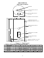
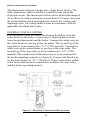
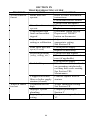
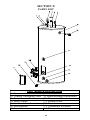
Figure 1 – Tank Layout
Table 1: Water Heater Dimension (Inches)
MODEL A B C D E F
40-Gal. 22 41-1/8 34-3/8 41-7/8 5-3/8 27-1/2
50-Gal. 22 46-1/4 40-1/8 47 5-3/8 27-1/2
65-Gal. 22 59-1/4 53-1/8 60 5-3/8 27-1/2
80-Gal. 24 59 52-7/8 59-3/4 5-3/8 27-1/2
DRAIN COUPLING- 3/4” NPT
DRAIN VALVE – 5/8” NH
TO BOILER RETURN
3/4” NPT
THERMOSTAT UNDER
COVER
FROM BOILER SUPPLY
3/4” NPT
TEMPERATURE AND
PRESSURE RELIEF VALVE
HOT WATER OUTLET
3/4” NPT
WIRING JUNCTION BOX
COLD WATER OUTLET
3/4” NPT
ANODES

9
Specifications continued-
Table 2: Water Heater Capacities
MODEL
Tank
Capacity
(Gal)
Coil
Volume
(Gal)
Dry
Weight
(Lbs)
Wet
Weight
(Lbs)
40-Gal. 38 2.5 170 470
50-Gal. 46 2.5 180 547
65-Gal. 60 2.5 196 695
80-Gal. 75 2.5 224 848
Table 3: AHRI Certified Water Heater Ratings
MODEL
First Hour
Rating
(Gal/Hr)
Continuous
Draw
Rating
(Gal/Hr)
Standby
Heat Loss
Rating
(°F/Hr)
Minimum
Output of
Heat Source
(BTU/Hr)
Minimum
Heat Source
Flow Rate
(Gal/Min)
40-Gal 123 98 1.1 65,000
8.0
50-Gal 133 98 0.9 65,000
8.0
65-Gal 148 98 0.7 65,000
8.0
80-Gal 158 98 0.6 65,000 8.0
NOTE: These certified ratings were obtained with a heat source
output and flow rate as specified in Table 3 and a 180°F boiler water
supply temperature. Other results will be obtained under different
conditions.
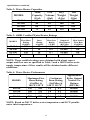
Table 4: Water Heater Performance
MODEL
Maximum First
Hour Rating
(Gal/Hr) @
140 °F 115 °F
Continuous
Draw Rating
(Gal/Min) @
140 °F 115 °F
Approximate
Boiler Output
Needed For
Ratings
(BTU/hr)
40-Gal. 190 285 2.6 4.2 140,000
50-Gal. 200 295 2.6 4.2 140,000
65-Gal. 210 305 2.6 4.2 140,000
80-Gal. 225 320 2.6 4.2 140,000
NOTE: Based on 200 °F boiler water temperature and 50 °F potable
water inlet temperature.

10
Specifications continued-
Table 5: Water Heater Performance
MODEL
Hot Water
Availability
(Minutes)
Coil Heat
Transfer Area
(Sq Ft)
Pressure Drop at
Rated Heat
Source Flow Rate
(Feet of Head)
40-Gal. 6.8 14.2 2.4
50-Gal. 8.6 14.2 2.4
65-Gal. 10.8 14.2 2.4
80-Gal. 13.5 14.2 2.4
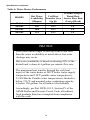
NOTICE
If the boiler takes longer to heat up from a cold start
than the water availability as noted above, hot water
shortage may occur.
Hot water availability is based on drawing 80% of the
heated tank volume at 4 gallons per minute flow rate.
The maximum heat transfer through the coil (heat
input) of the water heater at 240°F boiler water supply
temperature and 210°F potable water temperature is
23,500 Btu/hr. Potable water temperature is limited to
below 210 °F and nominal water-containing capacity
is below 120 gallons for all indirect-fired models.
Accordingly, per Part HLW-101.2, Section IV of the
ASME Boiler and Pressure Vessel Code, all indirect-
fired products listed are exempted from compliance
with the code.

11
SECTION III
GENERAL INFORMATION
FEATURES
This water heater contains the following features:
HEAT EXCHANGER -- The heat exchanger (coil) has 3/4” NPT
female fittings.
Water heaters with a double-wall heat exchanger meet the Uniform
Plumbing Code for installation in all potable water systems. The double-
wall construction provides protection in the event that either the potable
or hydronic heat exchanger barrier is penetrated. The fluid will move
along in integrated leak path within the heat exchanger, leaving the
exchanger through a weep hole located in the fittings. If a confirmed
leak occurs, contact the plumbing professional who installed the water
heater or the manufacturer, listed on the rating plate, for additional
guidance.
This indirect-fired water heater is appropriate for all potable heating
systems, even where a single-wall exchanger is not approved by the
authority having jurisdiction.
ADJUSTABLE THERMOSTAT – The temperature may be adjusted
from approximately 80°F to approximately160°F. The thermostat is
factory set at 120°F. It is recommended that lower temperatures be used
to avoid the risk of scalding. Refer to the “Warnings” and the section on
SCALDING in “Section VII – Operating Instructions.” It is further
recommended, in all cases, that the water temperature be set for the
lowest temperature that satisfies your hot water needs. This will also
provide the most energy efficient operation of the water heater and
minimizes scale formation.
Setting the water heater temperature at 120°F will reduce the risk of
scalds. Some states require settings to specific lower temperatures.

12
General Info continued-
TEMPERATURE AND PRESSURE RELIEF VALVE
WARNING
Keep clear of the combination temperature and pressure relief
valve discharge line outlet. The discharge may be hot enough to
cause scald injury. The water is under pressure and may splash.
For protection against excessive temperatures and pressure, install
temperature and pressure protective equipment required by local
codes, but not less than a combination temperature and pressure
relief valve certified by a nationally recognized testing laboratory
that maintains periodic inspection of production of listed
equipment or materials as meeting the requirements of the Standard
for Relief Valves and Automatic Gas Shutoff Devices for Hot Water
Supply Systems, ANSI Z21.22 and the Standard CAN1-4.4
Temperature, Pressure, Temperature and Pressure Relief Valves
and Vacuum Relief Valves. The combination temperature and
pressure relief valve must be marked with a maximum set pressure
not to exceed the maximum working pressure of the water heater.
The combination temperature and pressure relief valve must also
have an hourly rated temperature steam BTU discharge capacity
not less than the hourly rating of the water heater. The supplied
combination temperature and pressure relief valve, when properly
installed and unrestricted, will discharge the maximum input
produced by a 240°F (115°C) boiler supply temperature. A lower
boiler supply temperature will reduce the input required to be
discharged in the event of excessive potable water temperatures.
Install the combination temperature and pressure relief valve into
the opening provided and marked for this purpose on the water
heater.
Some models may already be equipped or supplied with a
temperature and pressure relief valve. Verify that the combination
temperature and pressure relief valve complies with local codes. If
the temperature and pressure relief valve does not comply with
local codes, replace it with one that does.

13
General Info continued-
SACRIFICIAL ANODES — Two sacrificial anode rods have been
installed in the tank head to extend tank life. The removal of any anodes,
except for inspection and/or replacement, will nullify the warranty. The
anode rods should be inspected annually to determine the amount of
sacrificial decay and replaced when necessary to prolong tank life.
Water conditions in your area will influence the time interval for
inspection and replacement of the anode rod. The use of a water softener
may increase the speed of anode consumption. More frequent inspection
of the anode is needed when using softened (or phosphate treated) water.
Contact the plumbing professional who installed the water heater or the
manufacturer, listed on the rating plate, for anode replacement
information.
WARNING
Install a discharge line so that water discharged from the
temperature and pressure relief valve will exit within six (6) inches
above, or any distance below, the structural floor and cannot
contact any live electrical part. The discharge line is to be installed
to allow for complete drainage of both the temperature and
pressure relief valve and the discharge line. The discharge opening
must not be subjected to blockage or freezing. DO NOT thread,
plug, or cap the discharge line. It is recommended that a minimum
clearance of four (4) inches be provided on the side of the water
heater for servicing and maintenance of the combination
temperature and pressure relief valve
Do not place a valve between the combination temperature and
pressure relief valve and the tank!

14
SECTION IV
PRE-INSTALLATION
UNPACKING
INSPECT SHIPMENT carefully for any signs of damage. If
damage is noted, do not install the product. Contact the shipper or
manufacturer. All equipment is carefully manufactured, inspected,
and packed. Our responsibility ceases upon delivery of the packaged
water heater to the carrier in good condition.
NOTE: Any claims for damage or shortage in shipment must be
filed immediately against the carrier by the consignee.
This water heater MUST be installed indoors out of the wind and
weather.
IMPORTANT DECISIONS REQUIRED BEFORE
INSTALLATION
SIZING
1. Boiler DOE Heating Capacity – The indirect-fired water
heater will provide the rated performance only if used in
conjunction with a heat source with a DOE heating capacity
(Heat Output) at least as much as the minimum noted in
Table 3. If the heat source has less capacity, the output of
the tank will be reduced. To determine the approximate
reduction in output from the tank use the following
formula:
New Rating = (maximum continuous draw rating) x
Actual Output of Heat Source
Minimum Output of Heat Source
For example, what would the continuous draw rating be if a 50-
gallon indirect-fired water heater were installed with a heat
source having a DOE heating capacity of 55,000 BTU/h?
Answer:
New Rating
= 98 gal/hr x (55,000 BTU/h)/(65,000 BTU/h)
= 98 gal/hr x 0.846 = 83 gal/hr

15
Pre-installation continued-
NOTICE
Increasing the boiler DOE heating capacity above the
values listed in Table 3 will not increase the rating of
the water heater.
2. Circulator Sizing – Refer to Table 5 for the corresponding
pressure drop through the coil for the given model. Calculate
the pressure drop of all straight pipe and fittings on the supply
and return of the water heater at the selected flow rate. Add
the piping/fitting pressure drop to the pressure drop through
the water heater coil.
Select a circulator that will provide an appropriate flow rate at
the combined pressure drop.
SYSTEM ZONE CONTROL
The indirect-fired water heater must be installed as a zone
separate from the space heating system. The domestic hot
water zone’s piping and circulator must be sized for a
minimum flow rate with all zones in use and a maximum flow
rate with only the water heater in use. For this reason, the
preferred method of zone control is with circulators.
1. Circulators – With space heating zones using
circulators, the indirect-fired heater should be added as
an additional zone with a circulator.
2. Zone Valves – Select a valve with a low-pressure drop
to assure adequate flow through the water heater.
3. Hybrid – The space heating zone can be zoned using
zone valves and the indirect-fired heater zoned with a
circulator.

16
Pre-installation continued-
DOMESTIC HOT WATER PRIORITY
Two options are available, Priority and Non-Priority.
1. Priority – Demand for space heating is interrupted or
postponed until the domestic hot water demand is satisfied.
This option provides maximum delivery of domestic hot
water. Priority is recommended when:
a) Boiler net output is 100,000 Btu per hour or less, or
b) When boiler output required to satisfy domestic hot
water demand is at least 50% of the boiler output
required to satisfy space heating demand, or
c) When an interruption in space heating can be tolerated
during a long domestic hot water draw.
2. Non-Priority – Boiler output is divided between space
heating and domestic hot water heating. Delivery of
domestic hot water can be reduced during simultaneous
space and domestic hot water heating operations,
depending on such factors as boiler output, boiler over-
sizing, number of space heating zones calling for heat, and
the ratio of domestic hot water load to space heating load.
Component Location
CAUTION
This water heater must be located in an area where leakage of the
tank, water line connections, or the temperature and pressure relief
valve will not result in damage to the area adjacent to the water
heater or to lower floors of the structure. When such locations
cannot be avoided, a suitable drain pan must be installed under the
water heater. The drain pan depth must be suitable for draining and
collecting water. The drain pan can be purchased from your
plumbing professional. The drain pan must be piped to an adequate
drain. The piping must be at least ¾ inch in diameter and pitched
for proper drainage.

17
Pre-installation continued-
Clearance from Combustible Materials
Top Sides Front Rear
0” 0” 0” 0”
Table 6 – Combustible Material Clearances
Recommended Service Clearances
Non-Piping
Side
Front
(Thermostat)
Rear
T & P Relief
Valve Side
4” 16” 0” 4”
Table 7 – Service Clearances
Appliance Location
1. Boiler Location – Locate the indirect-fired water heater as
close to the boiler as practical.
2. Fixture Locations – For fastest delivery of hot water, place the
indirect-fired water heater close to points of use.
Additional Recommended Components
1. Shut-off Valves – Allows isolation of water heater from
domestic water system and/or boiler system during service.
2. Unions – Allows water heater movement during service if
adequate clearance cannot be provided.
3. Thermal Expansion Tank – If the water heater is installed in
a closed water supply system, such as one having a back-flow
preventer in the cold water line, provide thermal expansion
control. Contact the water supplier or local plumbing inspector
for additional information.
CAUTION
Do not drop water heater. Do not bump water heater jacket against
floor.
WARNING
Do not plug the inlet and outlet tappings of tankless heater left
installed in the boiler.

18
Pre-installation continued-
MOVE THE WATER HEATER TO A PERMANENT
POSITION BY SLIDING OR WALKING.
SECTION V
WATER CONNECTIONS
NOTICE
For California installation this water heater must be braced,
anchored, or strapped to avoid falling or moving during an
earthquake. See instructions for correct installation procedures.
Instructions may be obtained from California Office of the State
Architect, 400 P Street, Sacramento, CA 95814.
WARNING
FAILURE TO INSTALL AND MAINTAIN A NEW, LISTED
TEMPERATURE AND PRESSURE RELIEF VALVE WILL
RELEASE THE MANUFACTURER FROM ANY CLAIM
WHICH MIGHT RESULT FROM EXCESSIVE
TEMPERATURE AND PRESSURES.
Hydrogen gas can be produced in an operating water heater that
has not had water drawn from the tank for a long period of time.
HYDROGEN GAS IS EXTREMELY FLAMMABLE. To prevent
the possibility of injury under these conditions, we recommend the
hot water faucet be opened for several minutes at the kitchen sink
before you use any electrical appliance that is connected to the hot
water system. If hydrogen is present, there will be an unusual
sound such as air escaping through the pipes as hot water begins to
flow. Do not smoke or have open flame near the faucet at the time
it is open.
Keep clear of the temperature and pressure relief valve discharge
line outlet. The discharge may be hot enough to cause scald injury.
The water is under pressure and may splash.

19
Water Connections continued-
INSTALL TEMPERATURE AND PRESSURE RELIEF
VALVE (if not factory installed)
INSTRUCTIONS FOR POTABLE CONNECTIONS
1. BEFORE PROCEEDING WITH THE INSTALLATION,
CLOSE THE MAIN WATER SUPPLY VALVE. After
shutting off the main water supply, open a faucet to relieve the
water line pressure to prevent any water from leaking out of the
pipes while making the water connections to the water heater.
After the pressure has been relieved, close the faucet. The
COLD water inlet and HOT water outlet are identified on the
top of the water heater. Make the proper plumbing connections
between the water heater and the plumbing system to the
house. Install a shut-off valve in the cold water supply line.
2. If this water heater is installed in a closed water supply system,
such as one having a back-flow preventer in the cold water
supply, provisions must be made to control thermal expansion.
DO NOT operate this water heater in a closed system without
provisions for controlling thermal expansion. Warranties do
not cover damages from thermal expansions such as pressure
bulges and/or deformities. A properly sized expansion tank will
alleviate most problems. Your water supplier or local
CAUTION
If sweat fittings are to be used, DO NOT apply heat to the nipples
on top of the water heater. Sweat the tubing to the adapter before
fitting the adapter to the water connections. It is imperative that
heat is not applied to the nipples containing a plastic liner.
WARNING
Temperature and pressure relief valve discharge piping must be
piped near the floor to eliminate potential of severe burns. Do
not pipe in any area where freezing could occur. Do not install
any shut-off valves, plugs or caps to the temperature and
pressure relief valve or piping.

20
Water Connections continued
plumbing inspector should be contacted on how to control this
situation.
3. After installation of the water lines, open the main water
supply valve and fill the water heater. While the water heater is
filling, open several hot water faucets to allow air to escape
from the water system. When steady streams of water flow
through the faucets, close them and check all water connections
for possible leaks.
4. NEVER OPERATE THE WATER HEATER WITHOUT
FIRST BEING CERTAIN THAT IT IS FILLED WITH
WATER.
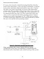
INSTRUCTIONS FOR BOILER CONNECTIONS
The indirect-fired heater connection labeled “To Boiler Return”
should be piped to the boiler return piping as close to the boiler as
possible and especially after any flow control or check valves in
the space heating return piping. The use of a union and a shut-off
valve is recommended. The use of a flow control or check valve is
required to prevent back flow through the water heater during
operation of the space heating system. Pipe and fittings between
the boiler and indirect-fired water heater should be ¾” diameter or
larger.
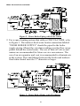
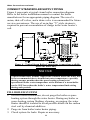
CONNECT WATER BOILER SUPPLY PIPING
1. For a space heating system that utilizes ZONE VALVES, refer
to Figure 2. The indirect-fired water heater connection labeled
“FROM BOILER SUPPLY” should be piped to the boiler
supply piping. Mount the circulator making sure the flow arrow
points toward the water heater. The use of shut-off valves and
unions are recommended for future service convenience. The
use of an air separator and vent is recommended to eliminate air
in the system. Pipe and fittings between the boiler and indirect-
fired water heater must be ¾” diameter or larger.
CAUTION
Maximum boiler water supply temperature to the indirect
heat exchanger must not exceed 240°F (116°C).
Page is loading ...
Page is loading ...
Page is loading ...
Page is loading ...
Page is loading ...
Page is loading ...
Page is loading ...
Page is loading ...
Page is loading ...
Page is loading ...
Page is loading ...
Page is loading ...
Page is loading ...
Page is loading ...
Page is loading ...
Page is loading ...
-
 1
1
-
 2
2
-
 3
3
-
 4
4
-
 5
5
-
 6
6
-
 7
7
-
 8
8
-
 9
9
-
 10
10
-
 11
11
-
 12
12
-
 13
13
-
 14
14
-
 15
15
-
 16
16
-
 17
17
-
 18
18
-
 19
19
-
 20
20
-
 21
21
-
 22
22
-
 23
23
-
 24
24
-
 25
25
-
 26
26
-
 27
27
-
 28
28
-
 29
29
-
 30
30
-
 31
31
-
 32
32
-
 33
33
-
 34
34
-
 35
35
-
 36
36


Bradford White DW-2-50L User manual
- Category
- Water heaters & boilers
- Type
- User manual
Ask a question and I''ll find the answer in the document
Finding information in a document is now easier with AI
Related papers
-
Bradford White SS-75-L User manual
-
Bradford White SW-2-40R-L User manual
-
Bradford White E32-50S User manual
-
Bradford White CEHD80 User manual
-
-
-
Bradford White LD-WH20L3-1 User manual
-
-
Bradford White CEA6-kW-3 User manual
Other documents
-
A.O. Smith 9260430146 User manual
-
Lochinvar Residential Electric water heater User manual
-
Crown Boiler Maxi Therm 2 Installation guide
-
A.O. Smith Commercial Semi-Instantaneous Technical Documents
-
Weil-McLain Aqua Plus User manual
-
A.O. Smith HWG-350 User manual
-
UTICA BOILERS HL40SK Set-up User manual
-
-
Weil-McLain GL-E223-ADOC 0311 User manual
-
Weil-McLain Aqua Plus 55 Owner's manual