
238-51313-00C REV 5/18
COMMERCIAL ELECTRIC WATER HEATER
THE WARRANTY ON THIS WATER HEATER IS IN EFFECT ONLY WHEN
THE WATER HEATER IS INSTALLED AND OPERATED IN
ACCORDANCE WITH LOCAL CODES AND THESE INSTRUCTIONS.
THE MANUFACTURER OF THIS HEATER WILL NOT BE LIABLE FOR
ANY DAMAGE RESULTING FROM FAILURE TO COMPLY WITH THESE
INSTRUCTIONS. READ THESE INSTRUCTIONS THOROUGHLY
BEFORE STARTING.
For your family’s comfort, safety and convenience, it is
recommended this water heater be installed and serviced by a
plumbing professional.
INSTALLATION & OPERATION
INSTRUCTION MANUAL
A Spanish language version of these instructions is available by
contacting the company listed on the rating plate.
La versión espãnola de estas instrucciones se puede obtener al
escribirle a la fábrica cuyo nombre aparece en la placa de
especificaciones.

2
TABLE OF CONTENTS
General Information .......................................................... 3
Installation.......................................................................... 4
Locating the Water Heater .................................................... 4
Water Connections ............................................................... 6
Electrical Connections ......................................................... 11
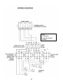
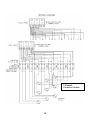
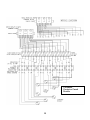
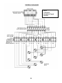
Wiring Diagrams ................................................................... 12
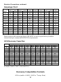
Amperage Chart .................................................................... 22
GPH Recovery Capacities .................................................... 22
General Operation ............................................................. 23
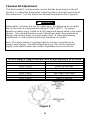
Thermostat Adjustment ........................................................ 24
Maintenance ....................................................................... 25
CONGRATULATIONS!
You have just purchased one of the finest water heaters on the
market today!
This installation, operation and instruction manual will explain
in detail the installation and maintenance of your new
Commercial Electric Water Heater. The Manufacturer strongly
recommends that you contact a plumbing professional for the
installation of this water heater.
We require that you carefully read this manual, as well as the
enclosed warranty, and refer to it when questions arise. If you
have any specific questions concerning your warranty, please
consult the plumbing professional from whom your water heater
was purchased. For your records we recommend that you write
the model, serial number and installation date of your water
heater in the maintenance section in the back of this manual.
This manual should be kept with the water heater.

3
GENERAL INFORMATION
This electric water heater’s design is certified by Intertek (ETL) and listed in
accordance with UL1453. CETL listed in accordance with Canadian National
Standard C22.2, No. 110-M90.
This water heater must be installed in accordance with local codes. In the
absence of local codes, install this water heater in accordance with the
N.E.C. Reference Book (latest edition).
The warranty for this water heater is in effect only when the water heater is
installed, adjusted and operated in accordance with these Installation and
Operating Instructions. The manufacturer will not be held liable for damage
resulting from alteration and/or failure to comply with these instructions.
This water heater has been designed and listed for the purpose of heating
potable water. The installation and use of this water heater for any purpose
other than the heating of potable water may cause damage to the water
heater and create a hazardous condition and nullify the warranty.
Do not use this appliance if any part has been under water. Immediately call
a qualified service technician to inspect the appliance and to replace any part
of the control system and/or any gas control, which has been under water.
Depending upon individual circumstances, it may be necessary to replace
the entire water heater.
Make sure that the rating plate on the water heater is referenced for certainty
that the correct voltage is being supplied to the water heater.
A sacrificial anode(s) is used to extend tank life. Removal of any anode,
except for inspection and/or replacement, will nullify the warranty. In areas
where water is unusually active, an odor may occur at the hot water faucet
due to a reaction between the sacrificial anode and impurities in the water. If
this should happen, an alternative anode(s) may be purchased from the
supplier that installed this water heater. This will minimize the odor while
protecting the tank.
CAUTION
Incorrect operation of this appliance may create a hazard to life and
property and will nullify the warranty.
Do not store or use gasoline or other flammable, combustible or
corrosive vapors and liquids in the vicinity of this or any other
appliance.
DANGER

4
General Information continued-
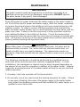
Additionally, the water heater should be flushed with appropriate dissolvers
to eliminate any bacteria.
INSTALLATION
Locating The Water Heater
This water heater MUST be installed indoors out of the wind and
weather.
This water heater must NOT be installed in any location where gasoline
or flammable vapors are likely to be present, unless the installation is
such to eliminate the ignition of gasoline or flammable vapors.
The location for the installation of this water heater is of utmost importance.
Before installing this water heater, consult the installation section of these
instructions. After reading these installation and operating instructions, select
a location for the water heater where the floor is level and is easily
accessible to a power supply and water connections.
It is recommended that the water heater be located near the center of
greatest hot water usage to prevent heat loss through the pipes. DO NOT
locate the water heater where water lines could be subjected to freezing
temperatures. Locate the water heater so that access panels and drain
valves are accessible.
IMPORTANT
Before proceeding, please inspect the water heater and its components for
possible damage. DO NOT install any damaged components. If damage is
evident, please contact the supplier where the water heater was purchased
or the manufacturer listed on the rating plate for replacement parts.
WARNING
This product contains one or more chemicals known to the State of California
to cause cancer, birth defects, or reproductive harm.
WARNING
Water heaters are heat-producing appliances. To avoid damage or injury,
there must be no materials stored against the water heater and proper care
must be taken to avoid unnecessary contact (especially by children) with
the water heater. UNDER NO CIRCUMSTANCES SHALL FLAMMABLE
MATERIALS, SUCH AS GASOLINE OR PAINT THINNER BE USED OR
STORED IN THE VICINITY OF THIS WATER HEATER OR ANY
LOCATION FROM WHICH FUMES COULD REACH THE WATER
HEATER.

5
General Information continued-
Water heater corrosion and component failure can be caused by the heating
and breakdown of airborne chemical vapors. Examples of some typical
compounds that are potentially corrosive are: spray can propellants, cleaning
solvents, refrigerator and air conditioning refrigerants, swimming pool
chemicals, calcium or sodium chloride, waxes and process chemicals.
These materials are corrosive at very low concentration levels with little or no
odor to reveal their presence. NOTE: DAMAGE TO THE WATER HEATER
CAUSED BY EXPOSURE TO CORROSIVE VAPORS IS NOT COVERED
BY THE WARRANTY. DO NOT OPERATE THE WATER HEATER IF
EXPOSURE HAS OR WILL OCCUR. DO NOT STORE ANY
POTENTIALLY CORROSIVE COMPOUNDS IN THE VICINITY OF THE
WATER HEATER.
This water heater must be located in an area where leakage of the tank or
water line connections and the combination temperature and pressure relief
valve will not result in damage to the area adjacent to the water heater or to
lower floors of the structure. When such locations cannot be avoided, a
suitable drain pan must be installed under the water heater. The drain pan
must have a minimum length and width of at least 4 in. (10.2 cm) greater
than the diameter of the water heater. The drain pan, as described above,
can be purchased from your plumbing professional. The drain pan must be
piped to an adequate drain. The piping must be pitched for proper drainage.
CLEARANCES
1. Minimum clearance to combustible material is 0 inches for the Top,
Sides, Front, and Rear of this water heater. However, it is
recommended that at least 18 inches (45.7 cm) from the Top, and
24 inches (61 cm) from the Front. Clearance for servicing may be
reduced down to minimum clearance to combustible material, but
service time and effort may be greatly increased.
2. Increase distances to provide clearances for servicing.
To comply with NSF requirements this water heater is to be:
a) Sealed to the floor with sealant, in a smooth and easily cleanable
way, or
b) Installed with an optional leg kit that includes legs and/or extensions
that provide a minimum clearance of 6” beneath the water heater.
Note: For California installation this water heater must be braced,
anchored, or strapped to avoid falling or moving during an earthquake.
See instructions for correct installation procedures. Instructions may
be obtained from the DSA Headquarters Office, 1102 Q Street, Suite
5100, Sacramento, CA 95811.

6
Water Connections
NOTE: BEFORE PROCEEDING WITH THE INSTALLATION, CLOSE THE
MAIN WATER SUPPLY VALVE.
After shutting the main water supply valve, open a faucet to relieve the water
line pressure to prevent any water from leaking out of the pipes while making
the water connections to the water heater. After the pressure has been
relieved, close the faucet. The cold water inlet line connects to the inlet
nipple at the base of the water heater. The hot water outlet line connects to
the nipple on top of the water heater. The fittings at the cold water inlet and
hot water outlet are dielectric waterway fittings with tapered male threads.
Make the proper plumbing connections between the water heater and the
plumbing system in the structure. Install a shut-off valve in the cold water
supply line.
If this water heater is installed in a closed water supply system, such as one
having a back-flow preventer in the cold water supply, provisions shall be
made to control thermal expansion. DO NOT operate this water heater in a
closed system without provisions for controlling thermal expansion. Your
water supplier or local plumbing inspector should be contacted on how to
control this situation.
After installation of the water lines, open the main water supply valve and fill
the water heater. While the water heater is filling, open several hot water
faucets to allow air to escape from the water system. After a steady stream
of water flows from the faucets, close them and check all water connections
for possible leaks. NEVER OPERATE THE WATER HEATER WITHOUT
FIRST BEING CERTAIN IT IS FILLED WITH WATER.
CAUTION
If sweat fittings are to be used, DO NOT apply heat to the nipples on the
water heater. Sweat the tubing to the adapter before fitting the adapter to
the water connections. It is imperative that heat is not applied to the
nipples containing a plastic liner.
IMPORTANT
FAILURE TO INSTALL AND MAINTAIN A NEW, LISTED
TEMPERATURE-PRESSURE RELIEF VALVE WILL RELEASE THE
MANUFACTURER FROM ANY CLAIM, WHICH MIGHT RESULT FROM
EXCESSIVE TEMPERATURE AND PRESSURES.

7
Water Connections continued-
WARNING
For protection against excessive temperatures and pressure, install
temperature and pressure protective equipment required by local codes,
but not less than a combination temperature and pressure relief valve
certified by a nationally recognized testing laboratory that maintains
periodic inspection of production of listed equipment or materials, as
meeting the Requirements for Relief Valves and Automatic Gas Shutoff
Devices for Hot Water Supply Systems, ANSI Z21.22, and the Standard
CAN1-4.4 Temperature, Pressure, Temperature and Pressure Relief
Valves and Vacuum Relief Valves. The combination temperature and
pressure relief valve must be marked with a maximum set pressure, not to
exceed the maximum working pressure of the water heater. The
combination temperature and pressure relief valve shall also have an
hourly rated temperature steam BTU discharge capacity not less than the
hourly input rating of the water heater.
Install the combination temperature and pressure relief valve into the
opening provided and marked for this purpose on the water heater
Note: Some models may already be equipped or supplied with a
combination temperature and pressure relief valve. Verify that the
combination temperature and pressure relief valve complies with local
codes. If the combination temperature and pressure relief valve does not
comply with local codes, replace it with one that does. Follow the
installation instructions above on this page.
Install a discharge line so that water discharged from the combination
temperature and pressure relief valve will exit within six (6) inches (15.3
cm) above, or any distance below the structural floor and cannot contact
any live electrical part. The discharge line is to be installed to allow for
complete drainage of both the temperature and pressure relief valve and
the discharge line. The discharge opening must not be subjected to
blockage or freezing. DO NOT thread, plug or cap the discharge line. It is
recommended that a minimum of four (4) inches (10.2 cm) be provided on
the side of the water heater for servicing and maintenance of the
combination temperature and pressure relief valve.
Do not place a valve between the combination temperature and pressure
relief valve and the tank.

8
Water Connections continued-
This water heater can deliver scalding temperature water at any faucet in the
system. Be careful whenever using hot water to avoid scalding injury.
Certain appliances, such as dishwashers and automatic clothes washers,
may require increased temperature water. By setting the thermostat on this
water heater to obtain increased temperature water required by these
appliances, you might create the potential for scald injury. To protect against
injury, you should install an ASSE approved mixing valve in the water
system. This valve will reduce point of discharge temperature by mixing cold
and hot water in branch supply lines. Such valves are available from the
manufacturer of this water heater or a local plumbing supplier. Please
consult with a plumbing professional.
WARNING
Hydrogen gas can be produced in a hot water system served by this
water heater that has not been used for a long period of time
(generally two weeks or more). Hydrogen gas is extremely
flammable. To reduce the risk of injury under these conditions, it is
recommended that the hot water faucet be opened for several
minutes at the kitchen sink before using any electrical appliance
connected to the hot water system. If hydrogen is present, there will
probably be an unusual sound such as air escaping through the pipe
as the water begins to flow. There should be no smoking or open
flame near the faucet at the time it is open.
CAUTION
INCREASING THE THERMOSTAT SETTING ABOVE THE PRESET
TEMPERATURE MAY CAUSE SEVERE BURNS AND CONSUME
EXCESSIVE ENERGY. HOTTER WATER INCREASES THE RISK OF
SCALD INJURY.

9
Water Connections continued-
can cause severe burns
are at highest risk of being
Children, disabled and elderly
instantly or death from scalds.
Water temperature over 125°F
Feel water before bathing or
before setting temperature
are available.
showering.
Temperature limiting valves
Review this instruction manual
at water heater.
scalded.
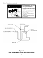
Figure 1
(Dual Temperature System With Mixing Valve)

10
Water Connections continued-
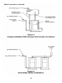
Figure 2
(Single Installation With Storage Tank Gravity Circulation)
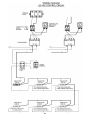
Figure 3
(Dual Water Heater Installation)

11
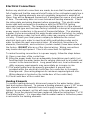
Electrical Connections
Before any electrical connections are made, be sure that the water heater is
full of water and that the manual shut-off valve in the cold water supply line is
open. If the heating elements are not completely immersed in water at all
times, they will be damaged (burned-out) if energized for even a short period
of time. The warranty does not cover burned-out heating elements. Check
the rating plate and wiring diagram before proceeding. This electric water
heater was built and wired in accordance with the INTERTEK testing
approvals requirements. The temperature-limiting device is of the manual
reset, trip-free type and has been factory installed to interrupt all ungrounded
power supply conductors in the event of thermostat failure. The plumbing
supplier in your area ordered this water heater wired at the factory to comply
with existing area codes, but local utility codes may require or allow other
circuitry. Consult your local power company to determine the correct
electrical hook-up in order to meet local utility and building codes and in
order to obtain the most economical rates. All electrical connections to
elements, thermostats, and contactors (certain models) have been made at
the factory. DO NOT alter any of the internal wiring. Wiring connections
may loosen during shipment. Check all connections for tightness.
To make the wiring connections to a power supply, follow the steps below.
A) Open cover door of the control box.
B) Bring the power leads from an adequately fused disconnect switch (not
furnished with the water heater due to varying state and local codes) and
connect to the terminal block. Long power lead runs, local ordinances or
utility company requirements may necessitate an increase in size.
C) This water heater must be properly grounded. A ground lug is
provided within the electrical control box for connection to a properly
sized ground. (See wiring diagram for minimum required ground size.
Wiring diagram is located on the inside door of the control box).
D) Close cover door of the control box.
Heating Elements
To replace heating elements, disconnect power to the water heater, drain
tank and replace element. To remove a heating element, use a 1 1/2” screw
type element wrench available from most supply houses. Do not over-
tighten the new element, as this will cause distortion in the new element
gasket. Once the element has been replaced, follow the instructions “To Fill
The Water Heater”. It is imperative that the water heater is full before power
is restored to the heating elements.

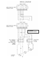
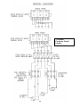
12
3 Element
Contactor Models

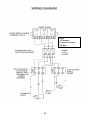
13
3 Element
Contactor Fused
Models

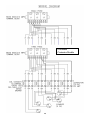
14
600V
3 Element
Contactor Fused
Models

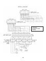
15
6 Element
Contactor Models

16
6 Element
Contactor Fused
Models

17
600V
6 Element
Contactor Fused
Models

18
9 Element
Contactor Models

19
9 Element
Contactor Fused
Models

20
600V
9 Element
Contactor Fused
Models
Page is loading ...
Page is loading ...
Page is loading ...
Page is loading ...
Page is loading ...
Page is loading ...
Page is loading ...
Page is loading ...
-
 1
1
-
 2
2
-
 3
3
-
 4
4
-
 5
5
-
 6
6
-
 7
7
-
 8
8
-
 9
9
-
 10
10
-
 11
11
-
 12
12
-
 13
13
-
 14
14
-
 15
15
-
 16
16
-
 17
17
-
 18
18
-
 19
19
-
 20
20
-
 21
21
-
 22
22
-
 23
23
-
 24
24
-
 25
25
-
 26
26
-
 27
27
-
 28
28


Ask a question and I''ll find the answer in the document
Finding information in a document is now easier with AI
Related papers
-
Bradford White MII50A243CF44 Installation guide
-
Bradford White 238-16152-00F User manual
-
Bradford White 30A-6-3-202C-BN Installation guide
-
Bradford White E32-50S User manual
-
-
Bradford White E32-50S3-3H06 User manual
-
Bradford White VR-600-(kW) User manual
-
Bradford White LD-20U3-1 User manual
-
-
Bradford White LD-WH20L3-1 User manual
Other documents
-
A.O. Smith 9500010447 Installation guide
-
HTP Heavy Duty Electric Water Heater Installation guide
-
State Water Heaters EN6-50-DORT 100 Installation guide
-
A.O. Smith 100227483 Installation guide
-
State Water Heaters EN6-50-DORT 100 Installation Instructions And Use & Care Manual
-
Bradford-White Corp Solar Water Heater User manual
-
State Industries 100348155 User manual
-
State SSE-5 , SSE-10 , SSE-20 , SSE-30 , SSE-40 , SSE-50 , SSE-65 , SSE-80 , SSE-100 , SSE-120 User manual
-
-
Reliance 1050DHPHT-NE Owner's manual