OM-537 Page 13
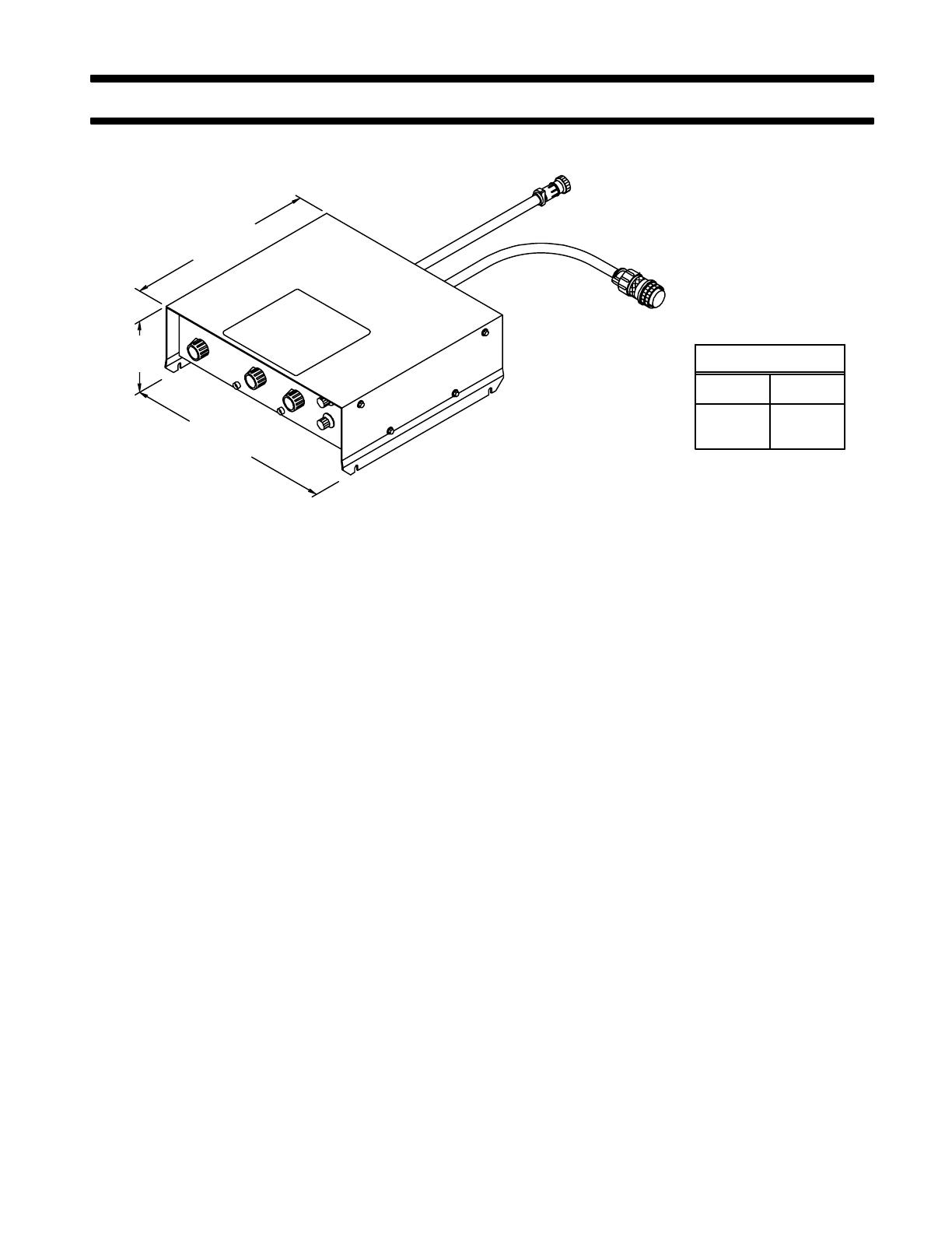
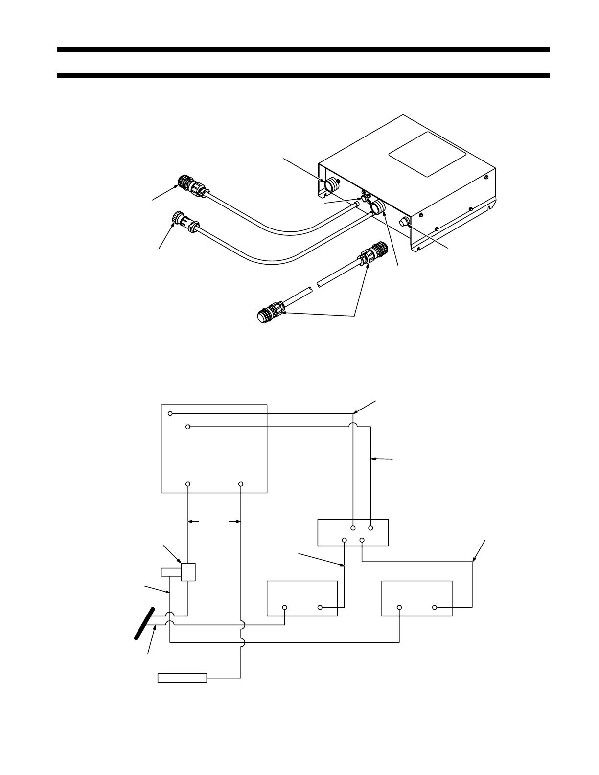
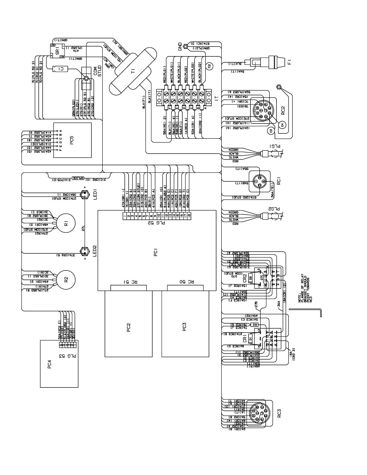
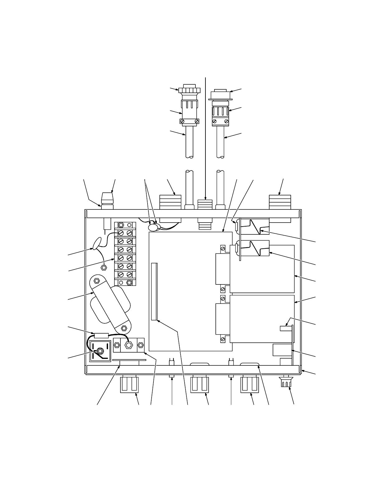
Figure 7-1. Main Assembly
Description Quantity
Part
No.
Dia.
Mkgs.
Figure 7-1. Main Assembly
Item
No.
1 046 432 HOLDER, fuse 1. . . . . . . . . . . . . . . . . . . . . . . . . . . . . . . . . . . . . . . . . . . . . . . . . . . . . . . . . . . . . . . . . . . . .
2 F1 *012 643 FUSE, minat-gl slo blo 1A 1. . . . . . . . . . . . . . . . . . . . . . . . . . . . . . . . . . . . . . . . . . . . . . . . . . . . . . .
3 C2,3 115 192 CAPACITOR 1. . . . . . . . . . . . . . . . . . . . . . . . . . . . . . . . . . . . . . . . . . . . . . . . . . . . . . . . . . . . . . . . .
4 RC2 089 646 RECEPTACLE, 10 pin MS-3102A-18-1P 1. . . . . . . . . . . . . . . . . . . . . . . . . . . . . . . . . . . . . . . . .
089 647 PLUG, 10skt amphenol MS-3106A-18-1S. . . . . . . . . . . . . . . . . . . .
073 332 CLAMP, cable AN-3057-10. . . . . . . . . . . . . . . . . . . .
5 604 571 CABLE, port No. 18 4/c (order by ft) 4ft. . . . . . . . . . . . . . . . . . . . . . . . . . . . . . . . . . . . . . . . . . . . . . . . . . .
6 079 531 CLAMP, cable strain relief 1. . . . . . . . . . . . . . . . . . . . . . . . . . . . . . . . . . . . . . . . . . . . . . . . . . . . . . . . . . . .
7 PLG1 048 284 HOUSING PLUG & SOCKETS, (consisting of) 1. . . . . . . . . . . . . . . . . . . . . . . . . . . . . . . . . . .
079 534 TERMINAL, female 1skt 14-18 wire 4. . . . . . . . . . . . . . . . . . . . . . . . . . . . . . . . . . . . . . . . . . . . . . . . . . . . .
8 RC1 048 283 RECEPTACLE w/PINS, (consisting of) 1. . . . . . . . . . . . . . . . . . . . . . . . . . . . . . . . . . . . . . . . . . .
079 535 TERMINAL, male 1 pin sz 16 18-14 wire 4. . . . . . . . . . . . . . . . . . . . . . . . . . . . . . . . . . . . . . . . . . . . . . . . .
9 PLG2 053 075 PLUG, 4 pin MS-3106A-14S-2P 1. . . . . . . . . . . . . . . . . . . . . . . . . . . . . . . . . . . . . . . . . . . . . . .
10 039 828 CLAMP, cable AN-3057-6 1. . . . . . . . . . . . . . . . . . . . . . . . . . . . . . . . . . . . . . . . . . . . . . . . . . . . . . . . . .
11 604 571 CABLE, port No. 18 4/c (order by ft) 4ft. . . . . . . . . . . . . . . . . . . . . . . . . . . . . . . . . . . . . . . . . . . . . . . .
12 PC1 108 451 CIRCUIT CARD, mother board 1. . . . . . . . . . . . . . . . . . . . . . . . . . . . . . . . . . . . . . . . . . . . . . . .
13 D1,2 026 202 DIODE, 1A 400V SP 2. . . . . . . . . . . . . . . . . . . . . . . . . . . . . . . . . . . . . . . . . . . . . . . . . . . . . . . .
14 RC3 039 718 RECEPTACLE, 10skt MS-3102A-18-1S 1. . . . . . . . . . . . . . . . . . . . . . . . . . . . . . . . . . . . . . .
039 716 PLUG, 10 pin Amphenol MS-3106A-18-1P. . . . . . . . . . . . . . . . . . . .
073 332 CLAMP, Amphenol AN-3057-10. . . . . . . . . . . . . . . . . . . .
15 079 844 SPRING, holddown-relay 2. . . . . . . . . . . . . . . . . . . . . . . . . . . . . . . . . . . . . . . . . . . . . . . . . . . . . . . . . .
048 029 CLIP, retaining-skt 2. . . . . . . . . . . . . . . . . . . . . . . . . . . . . . . . . . . . . . . . . . . . . . . . . . . . . . . . . . . . . . . . . . . .
027 811 SOCKET, relay 14 pin 2. . . . . . . . . . . . . . . . . . . . . . . . . . . . . . . . . . . . . . . . . . . . . . . . . . . . . . . . . . . . . . . . .
16 CR1,2 027 810 RELAY, encl 24VDC 4PDT 2. . . . . . . . . . . . . . . . . . . . . . . . . . . . . . . . . . . . . . . . . . . . . . . . . .
048 588 BRACKET, mtg-relay 1. . . . . . . . . . . . . . . . . . . . . . . . . . . . . . . . . . . . . . . . . . . . . . . . . . . . . . . . . . . . . . . . . .
17 PC3 108 449 CIRCUIT CARD, program board 1. . . . . . . . . . . . . . . . . . . . . . . . . . . . . . . . . . . . . . . . . . . . . . .
18 PC2 108 450 CIRCUIT CARD, program board 1. . . . . . . . . . . . . . . . . . . . . . . . . . . . . . . . . . . . . . . . . . . . . . .
19 PC53 105 673 CONNECTOR, plug 6 posn 1. . . . . . . . . . . . . . . . . . . . . . . . . . . . . . . . . . . . . . . . . . . . . . . . . .
20 PC4 110 655 CIRCUIT CARD, relay 1. . . . . . . . . . . . . . . . . . . . . . . . . . . . . . . . . . . . . . . . . . . . . . . . . . . . . . . .
21 +110 802 CASE SECTION, front/bottom/rear 1. . . . . . . . . . . . . . . . . . . . . . . . . . . . . . . . . . . . . . . . . . . . . . . . .
22 093 551 KNOB 2. . . . . . . . . . . . . . . . . . . . . . . . . . . . . . . . . . . . . . . . . . . . . . . . . . . . . . . . . . . . . . . . . . . . . . . . . . .
23 R1,2 035 897 POTENTIOMETER, C 1/T 2W 1000 ohm 2. . . . . . . . . . . . . . . . . . . . . . . . . . . . . . . . . . . . . .
24 097 922 KNOB, pointer 3. . . . . . . . . . . . . . . . . . . . . . . . . . . . . . . . . . . . . . . . . . . . . . . . . . . . . . . . . . . . . . . . . . . .
25 LED1,2 083 850 LIGHT, ind-red lens 24V 2. . . . . . . . . . . . . . . . . . . . . . . . . . . . . . . . . . . . . . . . . . . . . . . . . . .
26 PLG52 079 748 HOUSING, term header 18 pin 1. . . . . . . . . . . . . . . . . . . . . . . . . . . . . . . . . . . . . . . . . . . . .
27 072 253 STUD, ground 1. . . . . . . . . . . . . . . . . . . . . . . . . . . . . . . . . . . . . . . . . . . . . . . . . . . . . . . . . . . . . . . . . . . .
28 PC5,S1 109 207 CIRCUIT CARD, switch 1. . . . . . . . . . . . . . . . . . . . . . . . . . . . . . . . . . . . . . . . . . . . . . . . . . .
29 SR1 035 704 RECTIFIER, integ 40A 800V 1. . . . . . . . . . . . . . . . . . . . . . . . . . . . . . . . . . . . . . . . . . . . . . . . . .
30 C1 000 859 CAPACITOR, elctlt 220uf 35VDC 1. . . . . . . . . . . . . . . . . . . . . . . . . . . . . . . . . . . . . . . . . . . . . . .
31 T1 035 759 TRANSFORMER, control 115/36VCT 1. . . . . . . . . . . . . . . . . . . . . . . . . . . . . . . . . . . . . . . . . . .
32 TE1 038 772 BLOCK, term 20A 6P 1. . . . . . . . . . . . . . . . . . . . . . . . . . . . . . . . . . . . . . . . . . . . . . . . . . . . . . . .
33 C4 115 193 CAPACITOR 1. . . . . . . . . . . . . . . . . . . . . . . . . . . . . . . . . . . . . . . . . . . . . . . . . . . . . . . . . . . . . . . . .
R3 074 060 RESISTOR, C .5W 1K ohm 4. . . . . . . . . . . . . . . . . . . . . . . . . . . . . . . . . . . . . . . . . . . . . . . . . . . . . . . .
070 026 STAND-OFF, No. 6-32 x 7/16 4. . . . . . . . . . . . . . . . . . . . . . . . . . . . . . . . . . . . . . . . . . . . . . . . . . . . . . . . . . .
073 756 STAND-OFF, No. 6-32 x 5/8 2. . . . . . . . . . . . . . . . . . . . . . . . . . . . . . . . . . . . . . . . . . . . . . . . . . . . . . . . . . . .
010 476 BUSHING, strain relief 5/8 x .570 hole 2. . . . . . . . . . . . . . . . . . . . . . . . . . . . . . . . . . . . . . . . . . . . . . . . . . .
049 173 WRAPPER 1. . . . . . . . . . . . . . . . . . . . . . . . . . . . . . . . . . . . . . . . . . . . . . . . . . . . . . . . . . . . . . . . . . . . . . . . . .
134 327 LABEL, warning general precautionary 1. . . . . . . . . . . . . . . . . . . . . . . . . . . . . . . . . . . . . . . . . . . . . . . . . .
NAMEPLATE, (order by model & style number) 1. . . . . . . . . . . . . . . . . . . . . . . . . . . . . . . . . . . . . . . . . . . . . . . . . . . .
089 870 CABLE, interconnecting 10ft (consisting of) 1. . . . . . . . . . . . . . . . . . . . . . . . . . . . . . . . . . . . . . . . . . . . . .
089 647 PLUG, 10skt Amphenol MS-3102A-18-1S 1. . . . . . . . . . . . . . . . . . . . . . . . . . . . . . . . . . . . . . . . . . . . . . . .
073 332 CLAMP, cable Amphenol AN-3057-10 2. . . . . . . . . . . . . . . . . . . . . . . . . . . . . . . . . . . . . . . . . . . . . . . . . . .
073 140 CABLE, port No. 18 10/c (order by ft) 10ft. . . . . . . . . . . . . . . . . . . . . . . . . . . . . . . . . . . . . . . . . . . . . . . . . . .
039 716 PLUG, 10 pin Amphenol MS-3106A-18-1P 1. . . . . . . . . . . . . . . . . . . . . . . . . . . . . . . . . . . . . . . . . . . . . . .
*Recommended Spare Parts.
+When ordering a component originally displaying a precautionary label, the label should also be ordered.