Page is loading ...

INSTALLATION & OPERATING
INSTRUCTIONS
Catalog No. 6000.58C Effective: 12-01-18 Replaces: 07-01-17 P/N 241571 Rev. 4
92-103778-11-04
FOR YOUR SAFETY: Do not store or use gasoline or other flammable vapors and
liquids or other combustible materials in the vicinity of this or any other appliance. To
do so may result in an explosion or fire.
Heat Pump
Pool & Spa
Heater
NOTE: The instructions in this manual are for the use of qualified individuals specially trained and experienced
in the installation and maintenance of this type of equipment and related system components. Installation and
service personnel are required by some states to be licensed. Persons not qualified shall not attempt to install,
service, or maintain this equipment.
This manual should be maintained in legible condition and kept adjacent to the heat pump pool heater or in a
safe place for future use.
Professional
Series
9350HC, 9353HC,
10353HC, 10354HC
and 10355HC

2
Rev. 4 reflects the following:
Updated the “Efficiency Testing Note” on page 5.
ATTENTION: Please Take This Opportunity to Quickly Register Your Unit!!
While your unit is being installed by your professional and licensed installer of choice, Please Take This
Opportunity to Quickly Register Your Unit!! With the necessary information in hand, Registering your new Heat
Pump Pool Heater only takes a few moments and is the only way to assure any verifiable warranty procedures
d
uring the span of your unit's period of protection.
Using the diagram at the bottom of the page (Fig. i) please locate and record your model and serial number.
Once you have done this, please make sure you also have the following information on hand:
NAMEPLATE
• Name, phone number, and email address of homeowner
• physical address of where the unit is installed; please include any
'subdivision' or similar information
• any service challenges present at the house/neighborhood: gated
community, locked access at house, guard dog, etc.
• date of installation of the new unit
• name and phone number of the professional and licensed entity that
performed the installation for you
Fig. i: Model and Serial Number Location
With all of the above information in hand, please feel
free to call us at 800.260.2758 and ask to register your
brand new heat pump online:
http://warranty.raypak.com
You will be given a Warranty Registration Confirmation
number which you should notate and keep in one loca-
tion along with your Installation & Owner's Manual, a
copy of your warranty (provided with your manual) and
the above information.
This would also be a good time to review both the
manual and the warranty so that you are aware of how
to correctly operate your new equipment as well as
how to keep from voiding any aspects of your warran-
ty.
During the life of your unit, please feel free to use the
above phone number, or the one conveniently located
right on the unit, to contact us with any questions you
may have about operation, warranty, and/or service.
Thank You Very Much Choosing us to Satisfy Your
Pool Heating needs!!
Warranty Registration Confirmation #:

3
Water Chemistry
(
Corrosive water voids all warranties)
For your health and the protection of your pool equipment, it is essential that your water be chemically
b
alanced. The following levels must be used as a guide for balanced water.
• Occasional chemical shock dosing of the pool or spa water should not damage the heater providing
the water is balanced. However, it is highly recommended that the heat pump pool heater is isolated
via shut off valves before any aggressive chemical treatment.
• Automatic chemical dosing devices and salt chlorinators are usually more efficient in heated water.
Unless controlled, they can lead to excessive chlorine level which can damage your heater.
• Further advice should be obtained from your pool or spa builder, accredited pool shop, or chemical
supplier for the correct levels for your water.
Recommended Level(s) Fiberglass Pools Fiberglass Spas Other Pool & Spa Types
Water Temp. (Deg. F) 68 to 88 89 to 104 68 to 104
pH 7.3 to 7.4 7.3 to 7.4 7.6 to 7.8
Total Alkalinity (PPM) 120 to 150 120 to 150 80 to 120
Calcium Hardness (PPM) 200 to 300 150 to 200 200 to 400
Salt (PPM) 4500 MAXIMUM 4500 MAXIMUM 4500 MAXIMUM
Free Chlorine (PPM)* 2 to 3 2 to 3 2 to 3
Total Dissolved Solids (PPM) 3000 MAXIMUM** 3000 MAXIMUM** 3000 MAXIMUM**
*Free Chlorine MUST NOT EXCEED 5 PPM!
** In salt water chlorinated pools, the total TDS can be as high as 6000ppm.

4
Water Chemistry 3
Warnings 5
Pay Attention to These Terms 5
Introduction 6
Installation Considerations 6
Electrical Connections 7
Water Connections 9
Pressure Drop 10
HPPH Control Display 10
User Modes 11
HPPH Control Menus 12
USER MENU — HEAT/COOL Model
Type Selection 12
INSTALLER/SERVICE MENU —
HEAT/COOL Configuration 14
Control Settings 18
Set Current Time 18
C/F Display 18
Spa Max Temp 18
Pool Max Temp 18
Pump Periods 18
Temperature Control 18
Additional Features 18
Pump Control 18
Low Ambient (Outside) Lockout 18
Control Lock Box Mode 18
AUX Mode 19
Remote Pool Operation 20
Pool Heat Mode 20
Pool Cool Mode 20
Pool Auto Mode 20
TIMED SPA Mode 20
Fault History 20
Run Hours/Cycles 20
Compressor Start Delay 21
Minimum Run Time 21
Defrost Operation 21
3-Way Valve Control 21
Battery Back-up 21
High Water Temperature Limit 21
High Pressure Switch Lockout 21
Low Pressure Switch Lockout 22
Water Flow Switch 22
Controls 22
Digital Controls Operating
Instructions 23
To Increase or Decrease the Desired Water
Temperature (Pool or Spa Mode) 23
Select Temperature in °C or °F 23
Heat/Cool Operation 23
System Start-Up 23
Seasonal Start-Up or
Annual Check 23
Summer Shutdown 24
Freeze Protection 24
System Drain-Down 24
Continuous Pump Operation 24
Maintenance 24
Air Coil Cleaning 24
Cabinet Care (optional) 24
Unplug Condensation Drain Holes 24
Troubleshooting 25
Service Call Verification 28
Power Supply 28
Water Flow 28
Time Clock Adjustment 28
Set Factory Defaults 28
Plumbing Diagrams 29
Wiring Diagram — 208V/230V
Single-Phase — Digital Models 33
Wiring Diagram — 208V/230V
Three-Phase — Digital Models 34
Wiring Diagram — 460V 35
Wiring Diagram — 380V 36
Installing a Remote Control
Device 37
Heater 2-Wire Controllers (Heat Only) 37
3-Wire Controllers 37
2-Wire Controllers For “Chill” Mode -
Heat/Cool Models Only 37
CONTENTS

DANGER:
I
ndicates the presence of immediate hazards which will cause severe personal injury, death
or substantial property damage if ignored.
WARNING:
Indicates the presence of hazards or unsafe practices which could cause severe personal
injury, death or substantial property damage if ignored.
CAUTION:
Indicates the presence of hazards or unsafe practices which could cause minor personal
injury or product or property damage if ignored.
NOTE:
Indicates special instructions on installation, operation, or maintenance which are important
but not related to personal injury hazards.
Warnings — Pay Attention to These Terms
This manual, as well as the pool/spa heat pump pool heater itself, contains ANSI-approved product safety signs
and labels. Please read these signs and labels, as they convey important safety information about hazards that
may be potentially present in and around the heat pump pool heater.
CAUTION: Elevated water temperature can be
hazardous. The U.S. Consumer Product Safety
Commission has these guidelines:
1. Spa water temperatures should never exceed
104°F (40°C). A temperature of 100°F (38°C) is
considered safe for a healthy adult. Special cau-
tion is suggested for young children.
2. Drinking of alcoholic beverages before or during
spa or hot tub use can cause drowsiness which
could lead to unconsciousness and subsequently
result in drowning.
3. Pregnant Women Beware! Soaking in water over
102°F (39°C) can cause fetal damage during the
first three months of pregnancy resulting in the
birth of a brain-damaged or deformed child.
Pregnant women should stick to the 100°F (38°C)
maximum rule.
4. Before entering the spa or hot tub, users should
check the water temperature with an accurate
thermometer; spa or hot tub thermostats may err
in regulating water temperatures by as much as
4°F (2.2°C).
5. Persons with a medical history of heart disease,
circulatory problems, diabetes, or blood pressure
problems should obtain a physician's advice
before using pools or hot tubs.
6. Persons taking medications which induce drowsi-
ness, such as tranquilizers, antihistamines, or
anticoagulants, should not use spas or hot tubs.
5
WARNING: These heat pump pool heaters are
charged with R-410A refrigerant. Ensure that all
service work is done with gauges and equipment
suitable for R-410A.
CAUTION: Improper chemical content in a swim-
ming pool or spa can damage the heat pump pool
heater. DO NOT add pool/spa chemicals to the
poo/spa via the skimmer or any other apparatus
(feeder, chlorinator, etc.) that is on the influent side
(i.e. before) of the heater. This will damage the heat
pump pool heater and could void the heat pump pool
heater warranty. ALWAYS follow the product manu-
facturer’s directions when adding any chemicals to
your pool.
EFFICIENCY TESTING NOTICE: For purposes
of verifying or testing efficiency ratings, the test pro-
cedure in Title 10 APPENDIX P to Subpart B of Part
430 (Uniform Test Method for Measuring the Energy
Consumption of Pool Heaters) and the clarifying pro-
visions provided in the AHRI Operations Manual
1160 that were applicable at the date of manufacture
should be used for test set up and performance.
Charging Charts are available at https://www.ray-
pak.com/customer-support/heat-pump-charging-cha
rts. These should only be used by certified HVAC
technicians to check or adjust refrigerant charge for
proper operation.

Introduction
This manual contains important information on the
use, maintenance and troubleshooting of your new
heat pump pool heater. This unit must be properly
installed, maintained and operated for optimal per-
formance.
This heat pump pool heater is an extremely efficient,
economical machine designed specifically for swim-
ming pool heating. It is similar in design and operation
to a typical residential air conditioning system. The unit
employs a hermetic motor/compressor operating in a
refrigeration cycle to extract heat from ambient air and
deliver it to the circulating pool water.
As with all heat pump pool heaters, compared to other
types of heaters such as gas or oil-fired, this heat
pump pool heater has lower heating capacity on a
BTUH/hr basis. As a result, it will be required to oper-
ate longer to accomplish the desired results. It may, at
certain times, operate as much as 24 hours per day.
However, this should not be of concern to the owner,
because the unit is designed to operate continuously.
Even though it may operate continuously for many
hours, it will still heat the pool with greater economy
than other types of fossil fuel heaters.
Place a cover or blanket over the pool at night and
other non-use periods. This will keep evaporation, the
cause of main heat loss, to a minimum, and will greatly
reduce pool heating costs. During warmer weather, the
cover may be required only at night.
Installation Considerations
Situate the heat pump pool heater carefully to mini-
mize installation costs while providing maximum
efficiency of operation, and to allow adequate service
access, as follows:
• For unrestricted air intake and service access,
position each side of the unit at least 1 ft (30 cm)
from walls, pipes and other obstructions.
• Recirculation of cold discharge air back into the
evaporator coil will greatly reduce the unit’s heat-
ing capacity and efficiency.
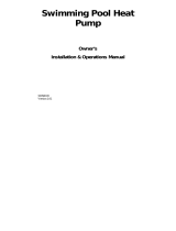
• This unit features an ‘up-flow’ discharge for quiet
operation. Air is pulled up through the evaporator
coil and discharged through the top grill. Allow at
least 5 ft (1.5 m) clearance above the unit for unre-
stricted air discharge. DO NOT install the unit
under a porch or deck. Refer to Fig. 1.
• To minimize water piping, locate the unit as close
as possible to the existing pool pump and filter.
• Irrigation water should be directed away from the
heat pump pool heater-water spray can damage
the heat pump pool heater.
WARNING: This pool/spa heat pump pool heater is
an electromechanical machine that incorporates a
p
ressurized refrigerant gas in a sealed system.
ONLY trained and qualified service personnel are
a
uthorized to install or service this equipment.
Without proper training and knowledge of such
equipment, any attempt to install or service the unit
could result in serious injury or even death.
WARNING: Do not install the unit within 3 ft of
f
ossil fuel burning heaters. Air intake along the
sides of this heat pump pool heater could disturb
the combustion process of the unit, and could
cause damage or personal injury.
• Mount the unit on a level, sturdy base, preferably
a concrete slab or blocks. The size of the base
should be at least 3 ft by 3 ft.
• You must install the 4 black rubber sound iso-
lation pads (each 2 inches square) that ship with
the unit. The pads are shipped in a bag with the
unions, gaskets and the I&O manual. Install pads
under the 4 corners of the unit to reduce vibra-
tion and sound transmission to the base.
CAUTION: The unit’s supporting base must be high
enough to keep it completely free of standing water
at all times.
WARNING: This unit is designed for outdoor instal-
lation; DO NOT install it in an enclosed area such as
a shed or garage.
6

7
G
AS
HEATER
AIR
F
LOW
IN
AIR
F
LOW
IN
AIR FLOW OUT
3 FT
MIN
12”
MIN
60”
MIN
Fig. 1: Installation Clearances
• Rain water run offs- the heat pump pool heater
can withstand normal rain. Install rain gutters to
prevent direct steams of rain water to the heat
pump pool heater.
• It is important to keep the area next to the heat
pump pool heater clear of shrubs, bushes and
chemicals containers. They could prevent air from
circulating fully through the heat pump pool heater,
and will affect the operation of the heat pump pool
heater or damage the heat pump pool heater.
• When installed in areas where freezing tempera-
tures can be encountered, drain the water circuit
to prevent possible freeze-up damage.
• For high wind installation requirements, refer to
the diagram on page 8.
Electrical Connections
Refer to the unit rating plate below the control panel for
precise power requirements for your unit, and for
ampacity and over-current protection requirements.
All wiring must be in accordance with the National
Electrical Code, NFPA No. 70, latest edition, and all
applicable state and local codes. Wiring diagrams are
located on pages 33 through 36.
• Locate the equipment disconnect means within 3
feet of the heater’s electrical enclosure, or as
close to the heater as possible. Always satisfy
applicable codes and standards.
• In sizing power wiring, be especially aware of up-
sizing requirements necessary due to wiring
distances. Always satisfy applicable codes and
standards.
• Electrical installation should be done by a licensed
electrician only.
This unit is pre-wired to work with external control sys-
tems, heat-on-demand options and other external time
clock overrides. Refer to the external control system’s
instructions, and page 19 of this manual, for installa-
tion information.
NOTE: Refer to the National Electrical Code, Article
680, for general requirements for swimming pools
and equipment, and to Article 440 for special consid-
erations necessary for circuits supplying hermetic
refrigeration motor/compressors.

8
Fig. 2: Hurricane Tie Down Instructions

Water Connections
1. Connect the heat pump pool heater in the return
water line between the filter and the pool/spa. See
the Plumbing Diagrams beginning on page 29.
2. Connect the filter outlet to the fitting marked
INLET/ENTREE at the bottom front of the unit.
3. Connect the fitting marked OUTLET/SORTIE to
the return piping to the pool/spa. Unit inlet/outlet
connection fittings are 2-inch PVC unions.
Water connections from the unit to the main return
line can be PVC pipe or flexible pipe approved for
the purpose and, in either case, should be at least
equal in size to the main pool/spa circulation pip-
ing.
4. Shut Off/Diverter valves, preferably three-way
valves which allows for a bypass route, on the inlet
and outlet lines of the HPPH are required if:
- water flow to the unit will exceed 60gpm
- to protect (completely bypass) the unit from
any harmful chemical treatments (i.e. Acid
wash, back-to-back super chlorinators, stain
treatments, etc.); or
- to be able to isolate the unit for
service/repair or freeze preparation and still
allow pool/spa circulation to continue
Please refer to the plumbing diagrams, starting on
pg. 29, for further instruction.
Please note that some municipalities do not allow
the use of a shut off valve on the effluent/outlet
side of any heating equipment, especially when
there is one on the inlet side. These entities typi-
cally instead allow a PVC tee and spring check
valve on the effluent/outlet side. This is allowed by
Raypak and can also double as your protection
from chemical feeders & chlorinators that our
downstream of the unit.
5. Operate the pump and check the system for leaks.
6. Drain plugs are located on each union fitting as
shown in Fig. 3 for draining the system during win-
terizing.
CAUTION: The heat pump pool heater inlet and
outlet connections are NOT interchangeable. They
must be connected as instructed below.
Fig. 3: Water Connections
WATER IN
WATER OUT
Model No. VAC in - Phase - Hz
Minimum Circuit
Ampacity (A)
Breaker Size (A)
M
IN
M
AX
9350HC 208/230 - 1 - 60 42.0 50 60
9353HC 208/230 - 3 - 60 34.0 40 50
10353HC 208/230 - 3 - 60 42.0 50 70
10354HC 460 - 3 - 60 26.0 30 40
10355HC 380 - 3 - 60 29.0 35 45
Table A: Typical System Electrical Power Requirements
9
NOTE: While it is possible to mount the upper union
with the drain plug vertically, Raypak has determined
that installing both unions with the drain plugs facing
down as shown in Fig. 3 provides for the best drain-
ing of the system.
CAUTION: When the drain plugs are removed for
draining the system, ensure that they are stored in a
safe place for re-installation when needed to restart
the system.

Pressure Drop
For system pressure drop information, refer to Table B
b
elow.
HPPH Control Display
The HPPH display is viewable from outside of the
heater. All operation and settings of the HPPH control
are accomplished through the use of the 3 buttons of
the user interface. These buttons are labeled as fol-
lows:
• MENU/SET – Scroll through available menus
and set changed values (MENU)
• UP – Increase values in the Adjust menu
• DOWN – Decrease values in the Adjust menu
The display uses a 2-line, 16-character backlit Liquid
Crystal Display (LCD) as the method for supplying
information. The backlight is normally off. The back-
light is on for 15 minutes after Power-Up and for 15
minutes after any button press. Use the LCD to setup
and monitor the operation of your heater.
If the membrane switch remains inactive for 180 sec-
onds (3 minutes), the screen will revert to the current
view.
On HEAT/COOL models, the options available by
pressing the MENU/SET (MENU) button are POOL
HEAT, POOL COOL, POOL AUTO, SPA, TIMED SPA
and OFF. The cooling setpoint can be adjusted in the
range of 50F to the Cooling Deadband value below the
Heating setpoint. This allows use in Plunge Pools.
Adjust the cooling setpoint accordingly.
Upon initial application of power, the HPPH control
briefly sets all segments on the LCD at power-up. On
a normal power-up, the control displays the current
software revision and the model type configuration
(HEAT ONLY, POWER DEFROST or HEAT/COOL) on
the LCD for 2 seconds and then resumes the user
selected mode it was in before power was interrupted.
The configuration for these units should be
HEAT/COOL.
Setpoints are read from non-volatile memory. If the
self diagnostic check indicates corrupted values,
“EEPROM Fault” is displayed on the LCD and opera-
tion is prohibited until setpoints are manually set.
If unit type has not been set (like during the replace-
ment of the HPPH control), the control prompts the
user to set the model type (HEAT ONLY, POWER
DEFROST, or HEAT/COOL) before any device opera-
tion is enabled. Installation in these models requires a
model type of HEAT/COOL to be selected.
Upon initial installation, there are several items that
must be defined and programmed depending on the
configuration and accessories intended to be con-
Fig. 4: HPPH Control Display
10
W
ARN
IN
G
:
Im
proper installation of
any type
of
autom
atic chem
ical feeders can result in serious
dam
age
t
o,
or
prem
ature
failure
of,
t
he heat
pum
p pool heater and m
ay void the heat
pum
p
pool heater warranty.
Instal
l a check valve and/or a
H
artford
l
oop AFTER
the
heat
pum
p
pool
heater
and
BEFOR
E any chl
ori
nati
ng devi
ces. Instal
l
any auto
-
m
ati
c chem
ical
feeders
AFTER
the heat pum
p pool
heater.
Table B: Pressure Drop Across Heat Pump Pool Heater
Note: Multiply the pressure drop in psi by 2.3067 to yield the pres-
sure drop in Ft. H
2
O Head (TDH).
Flow
(
gpm)
Pressure Drop
9350HC/
9353HC
10353HC/
1
0354HC/
10355HC
30 9 10
40 9 10
50 10 11
60 11 12
70 12 13
80 13 14

trolled by the HPPH control. These include: (1) 3-way
valve control (Yes or No), (2) Pump control (Yes or No
and then what type of control – 4-speed control or vari-
able speed control), and (3) Auxiliary control (Yes or
No and then what type – External Heat, Auxiliary
Output or Remote Output).
Once these choices are made, then additional infor-
mation relating to the establishing of pump periods,
pump speeds during each period and Return/Suction
Valve positions during each period must be deter-
mined and set in the control.
The options for the control can be very simple or very
detailed, depending upon each installation desires.
Once programming is completed, the control is ready
for operation.
The user may select one of several operating modes
since these units are HEAT/COOL models. Each
mode is selected by pressing the MENU button to
cycle between the modes. Each press of the MENU
button selects the next mode. There is no automatic
increment from continually pressing the MENU button.
In fact, continually pressing the MENU button (for 3+
seconds) will move the user into the USER Menu.
USER MODES
For HEAT/COOL models, the mode selections are:
OFF – POOL HEAT – POOL COOL – POOL AUTO
– SPA – TIMED SPA.
On HEAT/COOL models, there are additional opera-
tional modes available as noted below:
1. When POOL HEAT mode is selected, each press
of the UP or DOWN buttons will increase /
decrease the pool heating setpoint temperature.
Holding the UP or DOWN buttons down will speed
up the change of the temperature values.
2. When POOL COOL mode is selected, each press
of the UP or DOWN buttons will increase /
decrease the pool cooling setpoint temperature.
Holding the UP or DOWN buttons down will speed
up the change of the temperature values.
3. When POOL AUTO mode is selected, each press
of the UP or DOWN buttons will increase /
decrease the pool setpoint temperature. Holding
the UP or DOWN buttons down will speed up the
change of the temperature values.
4. When SPA mode is selected, each press of the UP
or DOWN buttons will increase / decrease the spa
setpoint temperature. Holding the UP or DOWN
buttons down will speed up the change of the tem-
perature values.
5. When TIMED SPA mode is selected, the display
will read “Up or Dn to Set”. This tells the user to
press the UP or DOWN buttons to set the desired
t
imer for timed SPA heating operation. Pressing
the UP button will increase the timer in 15 minute
increments (up to a total of 6 hours). Pressing the
DOWN button will decrease the timer by 15 minute
increments. The timer will start and the unit will
begin heating as necessary to maintain the Spa
setpoint temperature for this duration. At the end of
the timed period, the unit will automatically go to
the last operational state (POOL HEAT, POOL
COOL, POOL AUTO, or OFF). Once the unit turns
on, the display will toggle between the current Spa
water temperature and the current operating state
“Heating” for example. Pressing the MENU button
will change the display to show the time remaining
on the timer. Press the MENU button again to go
back to the current status.
The control saves the setpoint changes in non-volatile
memory and begins using them for heat demand dec-
sions after both the UP and DOWN buttons have been
released for 2+ seconds.
REMOTE Mode is accessed by pressing and holding
the UP and DOWN buttons simultaneously for 3 sec-
onds. When exiting the REMOTE mode, the control
always selects the OFF Mode.
If the UP, DOWN or MENU buttons are pressed while
in REMOTE mode, the display will read “Exit Remote
Mode to Adjust Temp”. Mode and temperature set-
points are not changed. Press and hold the UP and
DOWN buttons for 3 seconds to exit REMOTE Mode.
The INSTALLER/SERVICE menu can be accessed by
pressing and holding the UP and MENU buttons for 3+
seconds. The INSTALLER/SERVICE menu does not
affect operation of the unit which continues to operate
in the background. When in this mode, pressing the
UP or DOWN buttons will toggle through the various
information reported. Some items (Fault History and
Sensor Temperatures) have multiple values (press UP
or DOWN buttons to scroll through the additional infor-
mation. The INSTALLER/SERVICE menu may be
exited to return to the previous display be pressing the
UP and MENU buttons or it will automatically be exited
if no button is pressed within 60 seconds.
NOTE: Setpoints are not adjustable while in the
OFF mode or if the Control Lock Box mode is active.
11

12
Item Range
Default
Value
Access Level Description
Set Current
Time
12:00A–11:59P --- User
Selects current time – “A” or “P” will
indicate whether the set time is AM or
PM.
C/F Display Celsius/Fahrenheit Fahrenheit User Selects the units of measure for tem-
perature readings.
Spa Max Temp 65F–104F/18C–40C 104F User
Selects the maximum Spa tempera-
ture that the control can be adjusted
to in normal operation.
Pool Max Temp 65F–95F/18C–35C 95F User
Selects the maximum Pool tempera-
ture that the control can be adjusted
to in normal operation.
Pump Periods 0–4 User
Only available if Pump Operation in
the Installer’s Menu is set to “4-
Speed Enabled” or “Variable
Enabled”.
Pump On Time 1 12:00A–11:59P --- User Select ON time for Pump Period #1 to
take effect.
Pump Off Time 1 12:00A–11:59P --- User Select OFF time for Pump Period #1
to stop.
Pump Speed 1 1–4 if 4-Speed Enabled
0%–100% if Variable
Enabled
User On 4-speed pumps, this denotes the
selected pump output (which con-
nects to the pump for the selected
speed) for this pump period. On
Variable speed pumps, this denotes
the PWM signal to be provided to the
pump for pump operation.
Return Valve 1 Pool/Spa Pool User Select the position of a 3-way valve
located between the HPPH and the
Pool/Spa for this scheduled pump
period.
Suction Valve 1 Pool/Spa Pool User Select the position of the 3-way valve
located between the Pool/Spa and the
Pump for this scheduled pump period.
Pump On Time 2 12:00A–11:59P --- User Select ON time for Pump Period #2 to
take effect.
Pump Off Time 2 12:00A–11:59P --- User Select OFF time for Pump Period #2
to stop.
Table C: USER MENU — HEAT/COOL Model Type Selection
HPPH Control Menus
The USER menu is accessed by pressing and holding
t
he MENU button on the HPPH display for 3+ seconds.
This menu is intended for use by the end user to
change temperature settings and pump periods as
desired. There are different features and settings
required for different Model types. The model types
shown are HEAT ONLY, POWER DEFROST and
HEAT/COOL. For use in these units, the model type
selected should be “HEAT/COOL”. The following table
outlines the items noted on the display in the
HEAT/COOL configuration, the default values and
range of adjustable values as well as a brief descrip-
tion of the feature.

13
Item Range
Default
Value
Access Level Description
Pump Speed 2 1–4 if 4-Speed Enabled
0%–100% if Variable
Enabled
User On 4-speed pumps, this denotes the
selected pump output (which con-
nects to the pump for the selected
speed) for this pump period. On
Variable speed pumps, this denotes
the PWM signal to be provided to the
pump for pump operation.
Return Valve 2 Pool/Spa Pool User Select the position of a 3-way valve
located between the HPPH and the
Pool/Spa for this scheduled pump
period.
Suction Valve 2 Pool/Spa Pool User Select the position of the 3-way valve
located between the Pool/Spa and the
Pump for this scheduled pump period.
Pump On Time 3 12:00A–11:59P --- User Select ON time for Pump Period #3 to
take effect.
Pump Off Time 3 12:00A–11:59P --- User Select OFF time for Pump Period #3
to stop.
Pump Speed 3 1–4 if 4-Speed Enabled
0%–100% if Variable
Enabled
User On 4-speed pumps, this denotes the
selected pump output (which con-
nects to the pump for the selected
speed) for this pump period. On
Variable speed pumps, this denotes
the PWM signal to be provided to the
pump for pump operation.
Return Valve 3 Pool/Spa Pool User Select the position of a 3-way valve
located between the HPPH and the
Pool/Spa for this scheduled pump
period.
Suction Valve 3 PoolSpa Pool User Select the position of the 3-way valve
located between the Pool/Spa and the
Pump for this scheduled pump period.
Pump On Time 4 12:00A–11:59P --- User Select ON time for Pump Period #4 to
take effect.
Pump Off Time 4 12:00A–11:59P --- User Select OFF time for Pump Period #4
to stop.
Pump Speed 4 1–4 if 4-Speed Enabled
0%–100% if Variable
Enabled
User On 4-speed pumps, this denotes the
selected pump output (which con-
nects to the pump for the selected
speed) for this pump period. On
Variable speed pumps, this denotes
the PWM signal to be provided to the
pump for pump operation.
Return Valve 4 Pool/Spa
Pool
User Select the position of a 3-way valve
located between the HPPH and the
Pool/Spa for this scheduled pump
period.
Suction Valve 4 Pool/Spa Pool User Select the position of the 3-way valve
located between the Pool/Spa and the
Pump for this scheduled pump period.
NOTE: Make sure that the values for each setting are recorded for future reference or if the control ever needs
to be reset to Factory Defaults. All these values will need to be re-entered.

14
The Installer/Service menu is used by Installers and Service personnel to set up and troubleshoot the HPPH.
T
his menu is accessed by pressing and holding the UP and MENU buttons for 3+ seconds. WARNING: This
menu should never be used by the end user as changes can affect proper operation of the unit.
Table D: INSTALLER/SERVICE MENU — HEAT/COOL Configuration
Item Range
Default
Value
Access Level Description
Set Current
Time
12:00A–11:59P --- Installer Selects current time – “A” or “P” will
indicate whether the set time is AM or
PM.
Remote Pool Heat, Cool, Auto Cool Installer Selects unit operation when controlled
by remote.
Pump Periods 0–4 Installer Only available if Pump Operation in
the Installer’s Menu is set to “4-
Speed Enabled” or “Variable
Enabled”.
Pump On Time 1 12:00A–11:59P --- Installer Select ON time for Pump Period #1 to
take effect.
Pump Off Time 1 12:00A–11:59P --- Installer Select OFF time for Pump Period #1
to stop.
Pump Speed 1 1–4 if 4-Speed Enabled
0%–100% if Variable
Enabled
Installer On 4-speed pumps, this denotes the
selected pump output (which con-
nects to the pump for the selected
speed) for this pump period. On
Variable speed pumps, this denotes
the PWM signal to be provided to the
pump for pump operation.
Return Valve 1 Pool/Spa Pool Installer Select the position of a 3-way valve
located between the HPPH and the
Pool/Spa for this scheduled pump
period.
Suction Valve 1 Pool/Spa Pool Installer Select the position of the 3-way valve
located between the Pool/Spa and the
Pump for this scheduled pump period.
Pump On Time 2 12:00A–11:59P --- Installer Select ON time for Pump Period #2 to
take effect.
Pump Off Time 2 12:00A–11:59P --- Installer Select OFF time for Pump Period #2
to stop.
Pump Speed 2 1–4 if 4-Speed Enabled
0%–100% if Variable
Enabled
Installer On 4-speed pumps, this denotes the
selected pump output (which con-
nects to the pump for the selected
speed) for this pump period. On
Variable speed pumps, this denotes
the PWM signal to be provided to the
pump for pump operation
Return Valve 2 Pool/Spa Pool Installer Select the position of a 3-way valve
located between the HPPH and the
Pool/Spa for this scheduled pump
period.
Suction Valve 2 Pool/Spa Pool Installer Select the position of the 3-way valve
located between the Pool/Spa and the
Pump for this scheduled pump period.
Pump On Time 3 12:00A–11:59P --- Installer Select ON time for Pump Period #3 to
take effect.

15
Item Range
Default
Value
Access Level Description
Pump Off Time 3 12:00A–11:59P --- Installer Select OFF time for Pump Period #3
to stop.
Pump Speed 3 1–4 if 4-Speed Enabled
0%–100% if Variable
Enabled
Installer On 4-speed pumps, this denotes the
selected pump output (which con-
nects to the pump for the selected
speed) for this pump period. On
Variable speed pumps, this denotes
the PWM signal to be provided to the
pump for pump operation.
Return Valve 3 Pool/Spa Pool Installer Select the position of a 3-way valve
located between the HPPH and the
Pool/Spa for this scheduled pump
period.
Suction Valve 3 Pool/Spa Pool Installer Select the position of the 3-way valve
located between the Pool/Spa and the
Pump for this scheduled pump period.
Pump On Time 4 12:00A–11:59P --- Installer Select ON time for Pump Period #4 to
take effect.
Pump Off Time 4 12:00A–11:59P --- Installer Select OFF time for Pump Period #4
to stop.
Pump Speed 4 1–4 if 4-Speed Enabled
0%–100% if Variable
Enabled
Installer On 4-speed pumps, this denotes the
selected pump output (which con-
nects to the pump for the selected
speed) for this pump period. On
Variable speed pumps, this denotes
the PWM signal to be provided to the
pump for pump operation.
Return Valve 4 Pool/Spa
Pool
Installer Select the position of a 3-way valve
located between the HPPH and the
Pool/Spa for this scheduled pump
period.
Suction Valve 4 Pool/Spa Pool Installer Select the position of the 3-way valve
located between the Pool/Spa and the
Pump for this scheduled pump period.
Faults Last Installer/
Service
Fault history starting with the most
recent and going back to 10 last
faults. Using the UP/DOWN buttons
scrolls through the fault history. If
there are no faults present, the dis-
play will read “All Faults Clear”.
Clear Faults Installer/
Service
Holding down the UP and DOWN but-
tons for 3+ seconds clears the
recorded fault history and “Faults
Cleared” appears on the display.
Run Hours
XXXX
Cycles
XXXX
Installer/
Service
Displays the number of run hours that
the compressor has been running as
well as the number of cycles that the
unit has operated.

16
Item Range
Default
Value
Access Level Description
Voltage
Up/ Down for
More
Installer/
Service
Press UP or DOWN buttons to access
additional temperature measure-
ments.
Voltage View Only – VAC --- Installer/
Service
Displays the 24VAC voltage as meas-
ured by the control board.
Coil Temp View Only –
degrees F or C
Installer/
Service
Displays the coil temperature sensor
value – used for defrost operation.
Amb Temp View Only –
degrees F or C
Installer/
Service
Displays the ambient temperature
sensor value – used for Outside
Lockout operation and defrost.
Suct Temp View Only –
degrees F or C
Installer/
Service
Displays the suction line temperature
sensor value – used for EXV opera-
tion ONLY. Will not be shown if EXV
Disabled is selected.
EXV Temp View Only –
degrees F or C
Installer/
Service
Displays the EXV temperature sensor
value – ONLY available with EXV
Enabled AND EXV Temp Sensor uti-
lized. NOTE: This is ONLY utilized
when the pressure transducer is NOT
used.
Sat Temp View Only –
degrees F or C
Installer/
Service
Displays the pressure transducer con-
verted to a temperature. It is
displayed whenever EXV is enabled.
Water Temp View Only –
degrees F or C
Installer/
Service
Displays the water temperature sen-
sor value – used for temperature
operation
Installer Menu
Yes or No No Select YES and press the MENU but-
ton to gain access to additional
programming selections in this
Installer/Service Sub-menu. Select
No and the next MENU button press
returns to the Set Current Time
screen.
Pump Operation 4-Speed Enabled,
Variable Enabled,
Disabled
Disabled Installer/
Service Sub-
menu
If pump control through the HPPH is
desired, select the appropriate pump
mode – 4-Speed Enabled for discrete
speed control or Variable Enabled for
PWM control of pump.
Pump Heat Installer/
Service Sub-
menu
This feature selects the Digital input
(pump speed) for the pump to operate
during HPPH operation.
Valve Operation Enabled, Disabled Disabled Installer/
Service Sub-
menu
This feature allows control of 3-way
valves. Disabled is the default.
When Enabled, the control will seek
information as to whether the Return
and Suction valves should be posi-
tions for Pool or Spa positions for
each pump period.
Return Valve
Position 1 =
Pool/Spa Pool
Suction Valve
Position 1 =
Pool/Spa Pool
AUX Mode AUX OFF, AUX
OUTPUT, REMOTE
OUT, EXT HEAT
AUX OFF Installer/
Service Sub-
menu
See description of auxiliary mode
operation on page 19.

17
Item Range
Default
Value
Access Level Description
AUX1 On Time 12:00A-11:59P --- Installer/
Service Sub-
menu
Select ON time for AUX1 to take
effect.
AUX1 Off Time 12:00A-11:59P --- Installer/
Service Sub-
menu
Select OFF time for AUX1 to stop.
AUX2 On Time 12:00A-11:59P --- Installer/
Service Sub-
menu
Select ON time for AUX2 to take
effect.
AUX2 Off Time 12:00A-11:59P --- Installer/
Service Sub-
menu
Select OFF time for AUX2 to stop.
Cooling
Deadband
2F–10F / 1C–5.5C 6F Installer/
Service Sub-
menu
In Pool Auto mode, the cooling set-
point is the heating setpoint minus
this Cooling Deadband value.
Defrost Temp 20F–35F / -6.5C–1.5C 35F Installer/
Service Sub-
menu
This is the temperature measured on
the coil when the control goes into
Defrost mode.
Def Terminate 40F–60F / 4C–15.5C 50F Installer/
Service Sub-
menu
If the coil temperature reaches this
setpoint, Defrost will terminate. Other
Defrost algorithms are still operating
behinds the scene.
Outside Lockout Off,
30F–50F / -1C–10C
Off Installer/
Service Sub-
menu
The installer can program the control
to Lock out operation of the unit if a
specific outside temperature is meas-
ured. Off allows operation at any
ambient temperature.
Set Model Type HEAT ONLY, POWER
DEFROST,
HEAT/COOL
HEAT/
COOL
Installer/
Service Sub-
menu
Set at the factory. Will need to be set
by Installer during any replacement of
the control board.
EXV Disabled, Type 1,
Type 2
Disabled Installer/
Service Sub-
menu
Set at the factory on new units.
Select “Disabled” if unit equipped with
TXV for board replacement. EXV
Type 1 is 500 step EXV. EXV Type 2
is 1600 step EXV.
Change EXV to Yes/No Installer/
Service Sub-
menu
This screen asks if you really want to
change the EXV setting – the UP or
DOWN button must be pressed to
show YES before the EXV type will be
changed.
Brownout
Detection On
On/Off On Installer/
Service Sub-
menu
This function will shut down operation
of the unit if the 24VAC signal drops
below 18VAC to protect the unit from
Low Voltage. This feature can be
turned off as desired.
Set Factory
Defaults
Installer/
Service Sub-
menu
Press and hold both the UP and
DOWN buttons for 3+ seconds to
reset the factory defaults in the con-
trol. When reset, the screen will
display “Defaults Set”.
NOTE: Make sure that the values for each setting are recorded for future reference or if the control ever needs
to be reset to Factory Defaults. All these values will need to be re-entered.

18
Control Settings
The user can access these control settings by press-
ing and holding the MENU button for 5+ seconds. Any
changes to values are stored into the non-volatile
m
emory when the MENU button is pressed – which
also toggles to the next setting. Failure to press any
buttons for 60 seconds will cause the screen to revert
back to its previous operating mode screen. However,
the user mode can also be exited by pressing and
holding the MENU button for 5+ seconds.
Set Current Time
This allows setting of the current time. The time is fol-
lowed by an “A” or “P” for AM and PM respectfully. The
control has a 24-hour time clock – although it is NOT
a 7-day time clock. The time clock is used for control
of the pump periods.
C/F Display
This setting is used to define the units of measure for
all temperature readings. Fahrenheit is the default
value. You can change the setting to Celsius by tog-
gling the UP or DOWN button and then pressing mode
to lock in the change.
Spa Max Temp
This setting is used to define the maximum tempera-
ture that the control can be set at for the Spa
operation. The range is 65F – 104F. The default value
is 104F.
Pool Max Temp
This setting is used to define the maximum tempera-
ture that the control can be set at for the Pool
operation. The range is 65F – 95F. The default value
is 95F.
Pump Periods
When the Pump Operation in the Installer’s Menu is
set to “4-Speed Enabled” or “Variable Enabled”, this
allows the setting of Pump Periods from this menu.
When setting this parameter, the control displays
“Pump Periods” on the first line of the display. The
number of pump periods (0 – 4) is displayed on the
center of the 2
nd
line. Pressing the UP or DOWN but-
tons increments/decrements the number of pump
periods – factory default is 1. If a non-zero number of
pump periods is selected when the MENU button is
pressed, the control will prompt for On/Off times for
each of the selected number of pump periods.
Temperature Control
The control uses the appropriate Pool or Spa setpoint
as selected in the Operating mode. The heat demand
begins when the water temperature is 0.5F or more
c
older (or 0.5F or more hotter in cooling mode) than
the setpoint.
Additional Features
Pump Control
The control is equipped to control the system pump
(particularly if it is a Raypak VSP pump). The control
provides for an output for a single speed pump (0.75A
@ 24VAC maximum) as well as an output for a vari-
able speed pump (10mA @12 VDC). Four signals are
provided for selection of 4 discrete speeds for a vari-
able speed pump. The control can be configured to
provide a PWM signal on the speed1 output. The con-
trol will energize the pump at the requested speed for
each of the pump periods set in the program mode. If
a heat pump demand is present during a scheduled
pump operation, the pump runs at the override speed
(Speed 1) regardless of the scheduled speed. When
the pump is active because of scheduled operation
and there is no active heat demand, the control sets
the 3-ways valve outputs to the states set in the pro-
gram mode schedule.
Low Ambient (Outside) Lockout
The control is equipped with a Low Ambient Lockout
feature which will prevent the start of a new cycle if the
ambient temperature is lower than the programmed
value. This feature is accessed through the
Installer/Service Sub-menu as noted in Table D, page
17. The default value is “OFF”, but the temperature
can be adjusted between 30F and 50F. This feature
can be enabled if it is desired to not operate the unit if
the temperature falls below this value. NOTE: This
feature will NOT stop the operation of an existing
cycle, it will only prevent operation of a new cycle.
An open outdoor temperature sensor (display will read
“Air Temp -46F”) will trigger an “Outside Lockout” error
if the Low Ambient lockout is enabled. An open or
shorted (display will read “Air Temp 282F”) outdoor
temperature sensor will also cause the control to shut
off the compressor regardless of if the Low Ambient
lockout is enabled.
Control Lock Box Mode
The control is equipped with a Control Lockout feature
which is accessed by pressing and holding the MENU
and DOWN buttons for 5 seconds. The user will be
prompted to enter a 3-digit code. A cursor flashes
under each digit in the 3 digit code when that digit is
NOTE: See Table E on page 26 for Operational
Status Messages that you may see during normal
operation.

19
being set. Pressing the UP or DOWN buttons increas-
es or decreases the value and press the MENU button
to lock in that value. The cursor moves to the next digit
for setting. Once the last digit is selected (pressing
MENU) the display will ask to confirm the established
Lockout code. Pressing UP or DOWN until “YES” is
shown and then press the MENU button to confirm this
Lockout code. NOTE: Record this Lockout code for
future reference.
Pressing any button when the control is in Lockout
Mode will prompt the user for the Lockout code. The
display will read “Control Lockout – Enter PIN 000”. If
the PIN is entered incorrectly, the display will show
“Invalid PIN”. Pressing any button will return the user
to the lockout code screen.
Entering the correct Lockout code will result in the dis-
play showing “Lockout Cleared” and the display will go
to the current operating state of the unit.
Setting for total lockout operation without TIMED SPA
operation (only recommended on systems with pool
heat only):
1. Press the MENU button until SPA is displayed.
2. Press the DOWN button until the setpoint temper-
ature has been reduced to 65F or lower.
3. Press the MENU button for the next mode selec-
tion and set the desired setpoint temperature for
each mode as appropriate.
4. Program the Control Lock Box mode as noted
above.
AUX Mode
The control has the capability to control two auxiliary
outputs for various external uses (rating is 0.75A @
24VAC max.). There are 4 selectable modes within
the Installer/Service Sub-menu for auxiliary mode con-
trol. These include: AUX OFF (default), AUX
OUTPUT, REMOTE OUT, and EXT HEAT. The control
allows setting ON and OFF times for these 2 auxiliary
outputs in the Installer/Service Sub-menu.
1. AUX OUTPUT – When AUX OUTPUT is selected,
the AUX1 and AUX2 outputs turn ON/OFF from the
time schedule loaded into the control at installa-
tion. Time schedules for each output are
independent of each other. If the OFF time is
before the ON time, the control will assume the
Aux output is to be energized over midnight. If the
NOTE: Record this Lockout code for future refer-
ence.
time of day is not known due to a clock failure, the
AUX output schedules are not run.
2. REMOTE OUT – When REMOTE OUT is select-
ed, the AUX1 output is used to control another pool
heater (gas, HPPH or solar). This feature is ideal
for when using a HEAT PUMP / GAS HEATER
combo, where a Gas Heater will be providing 'back
up' heating for your Heat Pump Pool Heater. Gas
Heaters are usually used to assist when the tem-
perature is too cold for a Heat Pump Pool Heater
to heat the pool/spa water effectively on its own, or
when the target temperature will require a larger
amount of BTUs than what the Heat Pump Pool
Heater can provide on its own, during a given time
and/or outside conditions, in order to be achieved
within the operator's desired window of time. A
Heat Pump Pool Heater, as the more efficient
heating device when used in conjunction with a
Gas Heater, should be the equipment in control of
monitoring the pool/spa water temp and deciding
whether there is a Call for Heat. In the REMOTE
OUT mode, the 'Ext. Heater', i.e. Gas Heater, is
not allowed to heat the water unless the Heat
Pump Pool Heater is on as well.
To take advantage of this feature, set the Heat
Pump Pool Heater to the desired Target Temp, and
then set the Gas Heater to the temperature from
which the Heat Pump Pool Heater will no longer
truly need assistance. For example, if your deal-
er/installer's calculations, or prior experience,
determines that on your particular pool/spa, the
Heat Pump Pool Heater will no longer need assis-
tance getting the water to a desired temp of 80F
once the water reaches 70F, set the Heat Pump
Pool Heater to 80F and the Gas Heater to 70F.
The AUX1 output energizes 10 seconds after the
first unit/Heat Pump Pool Heater's compressor and
de-energizes when the first unit/Heat Pump Pool
Heater's compressor de-energizes. AUX2 output is
always OFF in this configuration.
REMOTE OUT (Multiple HPPHs) – The “Lead
HPPH” can control one or more “follower HPPH”
with a single set point temperature. The AUX1 out-
put energizes 10 seconds after the “Lead HPPH”
compressor and de-energizes after the “Lead
HPPH” compressor de-energizes. AUX2 output is
always OFF in this configuration.
3. EXT HEAT – When EXT HEAT is selected, AUX1
output is energized whenever there is a 1
st
stage
heat demand. This allows the use of a solar sys-
tem in conjunction with this unit and the control will

20
operate the solar system first and only bring this
unit on if the heating demand is NOT being met by
the solar system. AUX2 is always off in this con-
figuration.
The 2
nd
stage (HPPH) demand is initiated when
water temperature has remained more than 0.5F
colder than the heat setpoint for more than 2
hours, or when the water temperature is 1.5F or
more colder than the heating setpoint.
Remote Pool Operation
REMOTE Mode is accessed by pressing and holding
the UP and DOWN buttons simultaneously for 3 sec-
onds. When exiting the REMOTE mode, the control
always selects the OFF Mode. If the UP, DOWN or
MENU buttons are pressed while in REMOTE mode,
the display will read “Exit Remote Mode to Adjust
Temp”. Mode and temperature setpoints are not
changed. Press and hold the UP and DOWN buttons
for 3 seconds to exit REMOTE Mode.
The control displays “Remote Pool” on the first line of
the display while the 2
nd
line displays “Cool”, “Heat” or
“Auto”. Pressing the UP or DOWN buttons toggles
between these values. Factory default is “Cool”. The
control uses the value selected when the MENU but-
ton is pressed to advance to the next item.
Pool Heat Mode
The control is equipped with a mode which will auto-
matically heat the pool to the heating setpoint
established in the User’s menu.
Pool Cool Mode
The control is equipped with a mode which will auto-
matically cool the pool to the cooling setpoint
established in the User’s menu.
Pool Auto Mode
The control is equipped with a mode which will auto-
matically heat and cool the pool within the range of the
heating setpoint plus the Cooling Deadband (2-10F
adjustable – default 6F) established in the
Installer/Service Sub-menu. Example – pool heating
setpoint set at 80F and Cooling Deadband set at 6F –
unit will automatically heat the pool if the temperature
drops below 80F and will automatically cool the pool if
the temperature is above 86F.
TIMED SPA Mode
The control is equipped with a mode which will heat
the spa to the Spa Setpoint temperature for a specified
period of time selected in the TIMED SPA mode set-
up. NOTE: The Spa setpoint temperature CANNOT
be changed when operating in this mode. This func-
tionality will override all other program settings for the
period of time selected by the user during the TIMED
SPA initiation.
1. To activate the TIMED SPA feature, press the
MENU button until “TIMED SPA” is displayed on
the top line of the display.
2. Press the UP or DOWN buttons to select the
desired duration of spa heating (up to a maximum
duration of 6 hours in 15 minute increments).
3. The timer will start to count down from the selected
period of time and the HPPH will operate to heat
the spa water based on the previously selected
spa setpoint temperature setting.
4. When the TIMED SPA timer has expired, the con-
trol will return to the previous mode that it was in
when TIMED SPA was selected.
Fault History
The control is equipped to maintain fault history in the
Installer/Service menu. It will retain the last 10 faults
(starting with the most recent). If the fault history
exceeds 10 events, the earliest fault drops off when a
new fault occurs. NOTE: There is no time/date stamp
associated with each fault. This history is intended to
simply show what faults the unit has experienced.
When the “Faults Last” shows on the display, pressing
the UP button toggles to the most previous fault.
Pressing the UP button toggles through the recorded
faults. The faults are labeled on the first line of the dis-
play as Faults Last, Faults 2, Faults 3, etc.
Consecutive identical faults are only stored once.
Run Hours/Cycles
The control is equipped to monitor the number of run
hours of the unit and the cycles of operation. This is
accessible through the Installer/Service menu. These
values are not resettable. The “Run Hours” tracks the
number of hours that the compressor has been ener-
gized. This data is stored in non-volatile memory each
time the demand for heat is satisfied. Hours and min-
utes are stored, although only hours are displayed.
The “Cycles” tracks the number of times that the com-
pressor has been energized.
WARNING: If the Spa heating (in a pool/spa sys-
t
em) is controlled by an external controller, 3-way
valves MAY need to be manually adjusted in order to
use the TIMED SPA feature of this HPPH. Failure to
properly adjust the 3-way valves may result in over-
heating of the pool water or other undesirable
results.
/