Page is loading ...

XG0221
Installation & Maintenance Manual
• Theinstallationofthisreplacemustbedonebya
qualiedandcertiedgasapplianceinstaller.
• Checklocalcodesandreadallinstructionspriorto
installation.
®
C
US
WARNING:
FIRE OR EXPLOSION HAZARD
Failure to follow safety warnings exactly could result in serious injury,
death, or property damage.
—Donotstoreorusegasolineorotherammablevaporsand
liquidsinthevicinityofthisoranyotherappliance.
— WHAT TO DO IF YOU SMELL GAS
• Do not try to light any appliance.
• Do not touch any electrical switch; do not use any
phoneinyourbuilding.
• Leavethebuildingimmediately.
• Immediatelycallyourgassupplierfromaneighbour's
phone. Follow the gas supplier’s instructions.
• Ifyoucannotreachyourgassupplier,callthere
department.
—Installationandservicemustbeperformedbyaqualied
installer,serviceagencyorthegastter.
Distinction
DIRECT VENT INDOOR GAS FIREPLACE
DL6315, DL6315ST,
40,000 BTU/hr Natural Gas or Propane Gas
D6315, D6315ST
50,000 BTU/hr Natural Gas or Propane Gas
Installer: Leave this manual with the appliance.
Consumer: Retain this manual for future reference.
NOTICE
Label all wires prior to disconnection when servicing controls.
Wiring errors can cause improper and dangerous operation.
Verify proper operation after servicing
Installation and service must be performed by a qualied installer,
service agency or the gas tter.
Some materials used in the manufacturing process of this product can
expose you to Benzene which is known in the State of California to
cause cancer and birth defects or other reproductive harm. For more
information go to www.P65warnings.ca.gov
WARNING

XG02212
General
Congratulations on your purchase of a Montigo Fireplace.
With over 30 years of experience, Montigo is committed to providing
you with a gas fireplace that is not only a beautiful addition to your
space, but that is also designed and manufactured to the highest
safety, reliability and engineering standards.
We strongly encourage you to read and carefully follow the
instructions laid out in this Installation, Operation and Maintenance
Manual and retain it for your future reference. Pay special attention
to all cautions, warnings, and notices throughout this manual
intended to ensure your safety.
This manual covers installation, operation and maintenance. Lighting,
operation and care of this replace can be easily performed by the
homeowner. All installation and service work should be performed
by a qualied or licensed installer, plumber or gas tter as certied
by the state, province, region or governing body where the replace
is being installed.
This installation, operation and maintenance manual is applicable
to the models described in Table 1. Refer to your rating plate to
verify included options.
Warranty and Installation Information: (See Appendix B)
The Montigo warranty will be voided by, and Montigo disclaims any
responsibility for, the following actions:
• Modication of the replace and/or components including Direct-
Vent assembly or glass doors.
• Use of any component part not manufactured or approved by
Montigo in combination with this Montigo replace system.
• Installation other than as instructed in this manual.
• Consult your local Gas Inspection Branch on installation
requirements for factory-built gas replaces. Installation & repairs
should be done by a qualied contractor.
DL6315NI X 40,000 X X
DL6315LI X 40,000 X X
D6315NI-2 X 50,000 X X
D6315LI-2 X 50,000 X X
DL6315STNI X 40,000 X X
DL6315STLI X 40,000 X X
D6315STNI-2 X 50,000 X X
D6315STLI-2 X 50,000 X X
MODEL
Natural Gas
Liquid Propane
Gas Rating
(BTU hr)
Linear Burner w/
Glass Accessories
SIT Electronic
Ignition
Introduction
Safety Alert Key
Young children should be carefully supervised when they are in the
same room as the appliance. Toddlers, young children, and others
may be susceptible to accidental contact burns. A physical barrier is
recommended if there are at-risk individuals in the house. To restrict
access to a replace or stove, install an adjustable safety gate to keep
toddlers, young children, and other at-risk individuals out of the room
and away from hot surfaces

XG0221 3
General
MODEL
Natural Gas
Liquid Propane
Gas Rating
(BTU hr)
Linear Burner w/
Glass Accessories
SIT Electronic
Ignition
Contents
Safety Alert Key ........................................................................................................... 2
Introduction ................................................................................................................. 2
Section A: Before You Begin .............................................................................. 4
Installation Checklist ........................................................................................... 4
Standard Installation Checklist .......................................................................... 5
Rating Plate Sample............................................................................................. 6
Section 1: Product Dimensions ................................................................................. 7
Section 2: Framing ..................................................................................................... 9
Combustible Wall Clearances ............................................................................. 9
Raised Installation Framing - Single Sided ......................................................10
Raised Installation Framing - See Through .....................................................10
Framing the Single Sided Fireplace (Floor Installation) .................................11
Installing the Single Sided Fireplace ................................................................ 12
Installing the See Through Fireplace ............................................................... 12
Assemble Non Combustible Framing D/DL6315/ST (Detail) ........................13
Framing Box Assembly Single Sided ...............................................................14
Framing Box Assembly See-Through ..............................................................14
Section 3: Venting .....................................................................................................15
Section 3-3-1: Venting Layouts ............................................................................... 16
Vertical Termination .......................................................................................... 16
Vertical Termination - 2 Elbows .......................................................................16
Vertical Termination - 3 Elbows .......................................................................17
Horizontal Termination - 1 Elbow .................................................................... 17
Horizontal Termination - 2 Elbows .................................................................. 18
Horizontal Termination - 3 Elbows .................................................................. 19
Section 3-2: Installing a Roof Mounted Direct Vent Termination (PVTK1SS) ....20
Section 3-2-1: Venting Layout ...........................................................................20
Section 3-3: Installing a Wall Mounted Direct Vent Termination ........................21
Section 3-3-2: Venting Components ................................................................ 22
Section 3-3-2.2: Simpson Duravent Venting Components ...........................23
Section 3-3-2.3: ICC Venting Components* .................................................... 24
Section 3-3-2.4: Metalfab Venting Components* ..........................................24
Section 3-5: Heat Shields..........................................................................................25
Propane Conversion ................................................................................................. 27
Section 4: Wiring .......................................................................................................29
D6315 (ST) (N/L) I-2 Wiring Diagram ................................................................29
Installation of Electrical Supply ........................................................................ 29
DL6315 (ST) (N/L) I Wiring Diagram .................................................................30
Installation of the wall switch ...........................................................................30
CPI [Continuous Pilot Ignition] / IPI Jumper Cable Installation ............................31
“Why use CPI mode”? ........................................................................................31
The difference between IPI and CPI: ...............................................................31
Installing the CPI Jumper Cable ........................................................................31
Section 5: Installing the gas line .............................................................................. 32
Fuel Type ............................................................................................................. 32
Gas Pressure ...................................................................................................... 32
Gas Connection .................................................................................................. 32
Finishing Around the Fireplace ........................................................................ 33
Mantels & Surrounds ........................................................................................ 33
Section 8: Removing & Installing the Screen ......................................................... 34
Removing the Screen ........................................................................................ 34
Reinstalling the Screen ...................................................................................... 34
Removing & Installing the door ............................................................................... 35
Removing the door: ........................................................................................... 35
Reinstalling the door ......................................................................................... 35
Section 9: Installing the Fireglass ............................................................................ 36
Firestone & Fireglass Quantity ......................................................................... 36
Optional speckled stones ................................................................................ 36
Optional Log Set ................................................................................................ 37
Log Kit Installation ............................................................................................. 37
D6315 (ST) (N/L) I-2 Wiring Diagram ................................................................ 39
LED Strip Instructions ........................................................................................ 41
Before you begin: .............................................................................................. 42
For Single Sided Installation: ............................................................................ 42
For See-Through Installation: ........................................................................... 42
Installation: ......................................................................................................... 42
Before you begin: .............................................................................................. 45
Section 7: Finishing the fireplace ............................................................................ 47
Optional Remote Operation .................................................................................... 48
LED Remote Control Operation .............................................................................. 52
Pairing the remote to the module .................................................................. 52
Section 10: Cleaning and Maintenance ................................................................. 53
General ............................................................................................................... 53
Cleaning .............................................................................................................. 53
Appendix A: Venting Terminations ......................................................................... 55
Appendix B: Warranty .............................................................................................. 56
Appendix C: Amendment
(Gas Fireplace / Equipment sold in the State of Massachusetts) ........................ 57
Introduction to the Distinction Fireplace: ...................................................... 59
Section 6: Testing the system .................................................................................. 60
6-1: Testing the system before gas connection ............................................. 60
6-2: Testing the system with gas connection (Highly recommended) ..... 60
6-2-2: LED Operation Verification – ................................................................ 60

XG02214
General
IMPORTANT MESSAGE: SAVE THESE INSTRUCTIONS
The Distinction Series replaces must be installed in accordance with
these instructions. Carefully read all the instructions in this manual
rst. Consult the Local Gas Branch to determine the need for a permit
prior to starting the installation. It is the responsibility of the installer to
ensure this replace is installed in compliance with the manufacturers
instructions and all applicable codes.
Installation Checklist
• Determine the desired install location of your replace.
• See Section 1, Dimensions on Page 8, and refer to the Framing
Section 2 for details.
• Select the location of your termination and resulting vent run.
• Your selected termination location must be the highest point in the
Direct Vent installation.
• Should it be impossible to meet the venting requirements laid out
in Section 3: Venting, please contact your Montigo dealer regarding
the use of a Montigo Power Vent.
• Lay out the Vent run; calculating the required elbows and straight
runs of 5"/8" ex and/or rigid pipe.
• Layout Electrical Requirements refer to Section 4: Wiring, for Details.
• Refer to Section 5: Installing the Gas Line, for details on the gas
connection and access.
• Refer to local codes and guidelines for installation requirements.
• Installation and repairs should be done by a qualied contractor
and must conform to:
• Installations in Canada must conform to the local codes or in the
absence of local codes to the current version of Natural Gas and
Propane Installation Code, CSA B149. Electrical installations must
conform to the local codes or, in the absence of local codes, to the
current version of Canadian Electrical Code, CSA C22.1.1
• Installations in the USA must conform to the local codes or in the
absence of local codes to the current version of National Fuel Gas
Code, ANSI Z223.1/NFPA 54. Electrical installations must conform
to the local codes or, in the absence of local codes, to the current
version of the National Electrical Code, ANSI/NFPA 70. See Appendix
C for installation within the State of Massachusetts
Do not use this appliance if any part has been under water.
Immediately call a qualied service technician to inspect the appliance
and to replace any part of the control system and any gas control that
has been under water
Due to high temperatures, the appliance should be located out of
trac and away from furniture and draperies
Children and adults should be alerted to the hazards of high surface
temperature and should stay away to avoid burns or clothing ignition
A barrier designed to reduce the risk of burns from the hot viewing
glass is provided with this appliance and shall be installed for the
protection of children and other at-risk individuals
Clothing or other ammable material should not be placed on or near
the appliance
NOTICE
NOTICE
NOTICE
NOTICE
NOTICE
Installation and repair should be done by a qualied service person.
The appliance should be inspected before use and at least annually
by a professional service person. More frequent cleaning might be
required due to excessive lint from carpeting, bedding material, etc. It
is imperative that control compartments, burners, and circulating air
passageways of the appliance be kept clean
NOTICE
Section A: Before You Begin

XG0221 5
General
Standard Installation Checklist
This standard installation checklist is to be used by the installer in conjunction with, not instead of, the instructions contained within this
installation manual.
Customer Date Installed:
Install Address: Location of Fireplace:
Installer:
Model (circle one): D6315 DL6315 DL6315ST D6315ST
Dealer Phone:
Serial #:
*Only applicable for DL Series
YES NO IF NO, WHY NOT?
Appliance Install: Section 2
Framing complies with install manual.
Standos have been installed.
Proper clearances have been maintained.
Venting: Section 3
Venting conguration complies with vent diagrams.
Venting installed, fastened, and secured in place maintaining proper clearance.
Firestops installed.
Exterior wall/roof ashing installed and sealed in compliance with local building code.
Terminations installed and sealed in compliance with local building code.
Direct vent termination is highest point in vent assembly.
Wiring/Electrical: Section 4
Unswitched power provided to the appliance PPO box.
Low voltage wire connected to dry contact wall switch (non-powered)*
Gas: Section 5
Proper appliance for fuel type.
Was a conversion performed?
Leak check performed & inlet pressure veried.
Finishing: Section 6
Only non-combustible materials installed in non-combustible areas.
Clearances meet installation manual requirements
Mantels and/or projections comply with install manual
Appliance Setup: Section 7 through 9
Media, door, and screen installed according to install manual
Manual given to home owner.
Started appliance and veried no gas leaks exist.
Comments:

XG02216
General
Rating Plate Sample
LBA120x Distinction Series no CSA 27-02-2017
Figure 1 Rating Plate for D6315
LBA120x Distinction Series no CSA 27-02-2017
Figure 1.b Rating Plate for DL6315

XG0221 7
General
410
16
1
8
"
1672
65
13
16
"
356
14"
1602
63
1
16
"
405
15
15
16
"
1851
72
7
8
"
13
1
2
"
420
16
9
16
"
291
11
7
16
"
255
10
1
16
"
926
36
7
16
"
127
5"
203.200
8"
186
7
5
16
"
405
15
15
16
"
420
16
9
16
"
843
33
3
16
"
414
16
5
16
"
153
6"
276
10
7
8
"
64
2
1
2
"
160
6
5
16
"
943
37
1
8
"
GAS
SUPPLY
POWER
SUPPLY
REVISIONS
REV.
DESCRIPTION
DATE
CHANGED BY
-
.
- -
ITEM
NO.
PART NUMBER
DESCRIPTION
QTY.
Material
Revision
1
DL63061-20
Outer Shell Bottom
1
20 GA
Satin
B
2
DL63062-20
Outer Shell Side Right
1
20 GA
Satin
C
3
DL63063-20
Outer Shell Side Left
1
20 GA
Satin
D
4
DL63064-20
Outer Shell Top
1
20 GA
Satin
D
5
DL63065-20
Lower Brace
2
18 GA
Satin-
Coated
C
6
DL63052-20
Rear Back Panel Left
1
20 GA
Satin
G
7
DL63110-20
Rear Back Panel Center
1
20 Ga
Satin
Coat
G
8
DL63109-20
Rear Panel Back Right
1
20 GA
Satin
F
9
HCOL004
8" PIPE
1
B
10
HCOL003
8 COLLAR
1
22Ga.
SATIN
6
11
DL63170-10
5" Blanking Disk
4
20GA
Satin-
Coated
A
12
DL63165-20
Floor Bracket
2
20 GA
Satin-
Coated
B
13
EBOX491
PO BOX OUTER COVER
1
SATIN/20
C
14
PPOBOXONLY
Power Outlet Junction Box Only
1
A
15
DL63090-20
Light Tray
1
20 Ga
Type 304
SS WO/C
H
16
DL63159-20
Fan Stand
3
20 GA
Satin
C
17
DL63193-20
Fan Bracket
3
20 GA
Satin
C
18
Velcro Velcro
12
A
19
DL63166-10
Handle Bracket
4
16 GA
Satin-
Coated
E
20
DL63056-20
Screen Support Top
1
20 Ga.
Satin
C
21
DL63057-20
Screen Retainer Right
1
20 Ga.
Satin
Coat
D
22
DL63058-20
Screen Retainer Right
1
20 Ga.
Satin
Coat
D
23
DL63020-20
Control Drawer Support B
1
18 Ga
Satin
D
24
DL63134-20
Control Drawer Slide Rail
2
20 Ga
Satin
A
25
DL63040-20
Control Drawer
1
18 GA
Satin
G
26
DL63039-20
Control Drawer Slide
1
20 GA
Satin-
Coated
D
27
DL63108-20
Valve Cover Retainer
2
20 Ga
Satin
C
28
DL63054-20
Screen Support Btm Left
1
20 Ga
Satin
H
29
DL63055-20
Screen Support Btm Right
1
20 Ga
Satin
B
30
DL63107-20
Valve Cover
2
20 Ga
Satin
E
31
DL63066-20
Upper Brace Right
1
18 Ga
Satin
C
32
DL63067-20
Upper Brace Right
1
18 Ga
Satin
C
33
DL63005-20
Firebox Side Right
1
18 Ga
Satin
K
34
DL63006-20
Firebox Side Left
1
18 Ga
Satin
D
35
DL63010-20
Firebox Bottom Rail Rear
1
18 Ga
Satin
K
36
DL63130-20
Firebox Floor End Right
1
18 Ga
Satin
E
37
DL63011-20
Firebox Floor End Left
1
18 Ga
Satin
G
38
DL63133-20
Burner Mounting Bracket Right
1
18 Ga
Satin
C
39
DL63016-20
Firebox Bottom Front
1
18 Ga
Satin
J
40
DL63085-20
Light Tray Glass Retainer Short
2
18 Ga
Satin
D
41
GL1116
Light Tray Glass
1
5mm
Tempere
d Glass
E
42
DL63083-20
Light Tray Glass Retainer
2
18 Ga
Satin
D
43
DL63003-20
Firebox Top
1
18 Ga
Satin
L
44
DL63002-20
Air Intake Side
2
18 Ga
Satin
G
45
sitpilot IPI
SIT PILOT ASSY IPI GC3036 (NG)
1
46
DL63041-20
Media Tray Back
1
20 Ga
Satin
Coat
I
47
DL63146-20
Media Tray Front
1
20 Ga
Satin
Coat
I
48
DL63004-20
Air Intake Top
1
18 GA
Satin-
Coated
K
49
DL63001-20
Air Intake Bottom
1
18 Ga
Satin
F
50
DL63158-20
Air Takeoff Box
1
20 GA
Satin-
Coated
C
51
HCOL001
5 COLLAR
2
22Ga.
SATIN
4
52
IN1196
5 Collar gasket
3
1/8"
Manniglas
Grey
A
53
DL63043-20
Media Tray Skirt
2
20 Ga
Satin
E
54
DL63148-20
PILOT COVER
1
16 Ga
Type 304
SS W/C
C
55
GC3033b
Proflame Valve W?Stepper Motor
NG
1
A
56
DL63151-20
Valve Drawer
1
18 GA
Satin-
Coated
C
57
GL5110
Black Ceramic Glass (Side)
2
4mm
Black
Ceramic
Glass
A
58
DL63164-20
Glass Bracket
5
20 GA
Satin-
Coated
C
59
DL63152-20
Burner Tray Rail
6
18 GA
Satin-
Coated
B
60
HE38022-10
Wire Gasket Clamp
1
10 Ga.
Hot Roll
A
61
IN1125
Wire Gasket
1
CG365
1/4" (PSA
1 side
only)
B
62
DL63169-10
Rock Tray
2
CRSPERF3
16/20
C
63
DL63156-20
Collar, Male, Crimped
1
20 GA
Satin-
Coated
A
64
DL63171-20
Collar Seam Strip
1
20 GA
Satin-
Coated
A
65
DL63172-10
5" Collar
1
20GA
Satin-
Coated
B
66
GF1111
Gas Orifice Mount
1
0
67
OR0001
Gas Orifice P0512
1
68
GF2020
GF2020 90d. FORMED VENT. TUBE
1
B
69
DL63077-20
Media Burner
1
16 GA
Aluminize
d steel
D
70
DL63144-10
Burner Baffle
1
18 GA
Satin-
Coated
E
71
DL63087-20
DL63 Burner
1
16 GA
Aluminize
d Steel
I
72
GL5109
Black Ceramic Glass (Back)
3
4mm
Black
Ceramic
Glass
A
73
DL63149-20
Burner Mounting Bracket Left
1
18 GA
Satin-
Coated
C
74
DL63014-20
Rear Panel A
1
18 GA
Satin
F
75
DL63015-20
Rear Panel B
1
18 GA
Satin
E
76
DL63091-10
Light Cover
1
20 GA
Satin
A
77
DL63168-20
Light Cover Short
3
20GA
Satin-
Coated
D
78
DL63163-20
Light Cover Long 2
1
20GA
Satin-
Coated
B
79
DL63167-20
Light Cover Long
1
20GA
Satin-
Coated
C
80
DL63196-20
Reflection Board Bar
3
20 GA
Satin
B
81
DL63199-20
Door Frame
1
14 GA
Satin
B
82
GL4038
DL60 Window Glass
1
Ceramic
Glass
5mm
Neocera
m Glass
5mm
C
83
HW1152 Glass
Retainer
Glass Retainer Clip
4
.836mm x
19.05mm
Spring
Steel
A
84
DL63106-20
Door Spring Retainer
4
16 Ga.
Satin
Coat
B
85
HW2032
1/4"NC Machine Nut
4
0
86
DL63212-20
Door Latch
4
14 GA
Satin
B
87
DL63017-20
Rear Panel C
1
18 GA
Satin
C
88
DL63021-20
Middle Reflection Board
1
20 GA
Satin
B
89
DL63022-20
Left Reflection Board
1
20 GA
Satin
B
90
DL63023-20
Right Reflection Board
1
20 GA
Satin
B
91
DL63024-20
Reflection Board Side Bracket
2
18 GA
Satin
A
92
DL63025-20
Reflection Board Middle Racket
4
18 GA
Satin
B
93
GF1041
Connector, 3/8 NPT Male x 3/8 NPT
Male (7/16-27 UNS Female)
1
Brass
94
HW1232
Door Retainer Spring 1/2`` x 4.5``
4
ASTM
A401
B
95
DL63060
Safety Screen L62DF
1
Safety
Mesh /
Steel
Frame
D
96
DL63059-20
Screen Bracket
2
20 GA
Satin
B
97
DL63177-20
Valve Cover Bracket
2
20 GA
Satin
B
98
DL63178-20
Valve Cover Left
1
20 GA
Galv. 1/8
Holes
B
99
DL63179-20
Valve Cover Right
1
20 GA
Galv. 1/8
Holes
B
100
DL63180-20
Sidewall Spacer
4
26 GA
Satin
A
101
DL63181-20
Backwall Spacer
2
26 GA
Satin
A
102
DL63248-10
5" Plate Collar
6
20GA
Satin-
Coated
A
103
1-2 valve
Safety Valve
1
Material
<not
specified
>
A
104
1-2 valve handle
1
Material
<not
specified
>
A
105
Pan Cross Head_AI
1
106
DL63114-20
Lower Door Retainer
2
18 Ga
Satin
A
107
Pipe-10
2
Material
<not
specified
>
A
108
Pipe-11
2
Material
<not
specified
>
A
109
Pipe-12
1
Material
<not
specified
>
A
110
DL63240-20
Top Plate
1
20 GA
Satin
D
111
DL63241-20
Bottom Plate
1
20 GA
Satin
D
112
EC1466
Fan L/H
3
Material
<not
specified
>
A
113 COLL071-20
5" Collar
10
22 GA
Satin-
Coated
B
115
DL63044-10
Service Door
1
20 GA
Satin
B
116
HW1153
Door Retainer Bolt
4
0
117
IN1140
Orifice Mount Gasket
1
1/8"
Ceramic
Paper
A
118
EBOX492
PO BOX INNER COVER
1
SATIN/20
B
119
EC1220
CLAMP CONNECTOR, 1/2", SL20C20
1
B
120
CLF-DL63S
DL63-Side Ceramic Fiber Liner
1
A
121
CLF-DL63B
DL63-Back Ceramic Fiber Liner
3
A
122
DL63238-10
2
Material
<not
specified
>
A
123
DL63239-10
2
Material
<not
specified
>
A
124
DL72119-20
TV Kit - Bottom Bracket
3
18 GA
Satin
A
125
DL72114-20
TV Kit - Left Side
1
20 GA
Satin
B
126
DL72116-20
TV Kit - Right Side
1
20 GA
Satin
B
127
DL72112-20
TV Kit - Back Slot
1
20 GA
Satin
A
128
DL72121-20
TV Kit - Support Bracket
2
20 GA
Satin
A
129
DL72120-20
TV Kit - Back Support Bracket
2
20 GA
Satin
A
130
DL72118-20
TV Kit - Top Bracket
3
18 GA
Satin
B
131
DL72117-20
TV Kit - Back Slot Bracket
1
20 GA
Satin
A
132
DL63251-20
TV Kit - Top Face Bracket
1
20 GA
Satin
A
133
DL63252-20
TV Kit Isolation Plate
1
20 GA
Satin
A
134
HW1235
4x8mm SSF, Closed end rivet
2
1:32
DWG. NO.
SHEET 2 OF 2
WEIGHT:
DL63-Full Assembly 16
Finish
MATERIAL
DIMENSIONS ARE IN INCHES
TOLERANCES:
FRACTIONAL
1/32"
TWO PLACE DECIMAL
.015"
THREE PLACE DECIMAL
.005"
ANGULAR
.5
ALL BENDS ARE ASSUMED
TO BE 90
UNLESS NOTED
OTHERWISE.
Revision / Date
Drawn by
DATE
NAME
23/12/2016
22 GA Satin
THE INFORMATION CONTAINED IN THIS DRAWING IS THE SOLE PROPERTY OF CANADIAN HEATING PRODUCTS. ANY REPRODUCTION IN PART OR AS A WHOLE WITHOUT THE WRITTEN PERMISSION OF CANADIAN HEATING PRODUCTS IS PROHIBITED.
PROPRIETARY AND CONFIDENTIAL
Y:\Products\Residential Products\R&D Projects\DL63\Cad Drawings\DL63-Full Assembly 16
December-11-18 9:03:59 AM
SCALE
DM
Description
DL63-Full Assembly 16
Revision
Figure 2. DL6315, D6315 Fireplace dimensions (Tolerance ± ⅛").
SINGLE SIDED
Thereplacedimensionsareshownbelow:
Section 1: Product Dimensions

XG02218
General
410
16
1
8
"
1666
65
9
16
"
1628
64
1
8
"
403
15
7
8
"
84
3
5
16
"
84
3
5
16
"
469
18
7
16
"
1851
72
7
8
"
14
9
16
"
291
11
7
16
"
255
10
1
16
"
926
36
7
16
"
467
18
3
8
"
234
9
3
16
"
127
5"
203
8"
469
18
7
16
"
842
33
1
8
"
414
16
5
16
"
276
10
7
8
"
153
6"
63
2
1
2
"
GAS
SUPPLY
POWER
SUPPLY
REVISIONS
REV.
DESCRIPTION
DATE
CHANGED BY
-
.
- -
ITEM
NO.
PART NUMBER
DESCRIPTION
QTY.
MATERI
AL
REVISION
1
DL63ST006-20
Firebox Side Left
1
18 GA
Satin
C
2
DL63ST004-20
Air Intake Top
1
18 GA
Satin-
Coated
A
3
DL63001-20
Air Intake Bottom
1
18 Ga
Satin
F
4
DL63158-20
Air Takeoff Box
1
20 GA
Satin-
Coated
C
5
HCOL001
5 COLLAR
2
22Ga.
SATIN
4
6
IN1196
5 Collar gasket
3
1/8"
Mannigl
as Grey
A
7
DL63ST005-20
Firebox Side Right
1
18 GA
Satin
B
8
DL63ST003-20
Firebox Top
1
18 Ga
Satin
D
9
DL63016-20
Firebox Bottom Front
1
18 Ga
Satin
J
10
DL63ST017-20
Firebox Bottom Back
1
18 Ga
Satin
E
11
DL63011-20
Firebox Floor End Left
1
18 Ga
Satin
G
12
DL63130-20
Firebox Floor End Right
1
18 Ga
Satin
E
13
DL63133-20
Burner Mounting
Bracket Right
1
18 Ga
Satin
C
14
IN1125
Wire Gasket
1
CG365
1/4"
(PSA 1
side
only)
B
15
HE38022-10
Wire Gasket Clamp
1
10 Ga.
Hot Roll
A
16
GF1111
Gas Orifice Mount
1 0
17
OR0001
Gas Orifice P0512
1
18
GF2020
GF2020 90d. FORMED
VENT. TUBE
1
B
19
DL63077-20
Media Burner
1
16 GA
Aluminiz
ed steel
D
20
DL63144-10
Burner Baffle
1
18 GA
Satin-
Coated
E
21
DL63087-20
DL63 Burner
1
16 GA
Aluminiz
ed Steel
I
22
DL63085-20
Light Tray Glass Retainer
Short
2
18 Ga
Satin
D
23
DL63083-20
Light Tray Glass Retainer
2
18 Ga
Satin
D
24
GL1116
Light Tray Glass
1
5mm
Temper
ed
Glass
E
25
DL63002-20
Air Intake Side
2
18 Ga
Satin
G
26
DL63152-20
Burner Tray Rail
6
18 GA
Satin-
Coated
B
27
DL63146-20
Media Tray Front
1
20 Ga
Satin
Coat
I
28
DL63041-20
Media Tray Back
1
20 Ga
Satin
Coat
I
29
DL63169-10
Rock Tray
2
CRSPER
F316/20
C
30
DL63148-20
PILOT COVER
1
16 Ga
Type
304 SS
W/C
C
31
DL63151-20
Valve Drawer
1
18 GA
Satin-
Coated
C
32
GC3033b
Proflame Valve
W?Stepper Motor NG
1
A
33
DL63156-20
Collar, Male, Crimped
1
20 GA
Satin-
Coated
A
34
DL63171-20
Collar Seam Strip
1
20 GA
Satin-
Coated
A
35
DL63168-20
Light Cover Short
3
20GA
Satin-
Coated
D
36
DL63167-20
Light Cover Long
2
20GA
Satin-
Coated
C
37
DL63163-20
Light Cover Long 2
3
20GA
Satin-
Coated
B
38
DL63ST153-20
Lower Brace
2
18 GA
Satin-
Coated
D
39
DL63090-20
Light Tray
1
20 Ga
Type
304 SS
WO/C
H
40
DL63043-20
Media Tray Skirt
2
20 Ga
Satin
E
41
DL63ST072-20
Upper Brace Right
2
18 Ga
Satin
C
42
GL5110
Black Ceramic Glass
(Side)
2
4mm
Black
Cerami
c Glass
A
43
DL63172-10
5" Collar
1
20GA
Satin-
Coated
B
44
DL63164-20
Glass Bracket
2
20 GA
Satin-
Coated
C
45
DL63149-20
Burner Mounting
Bracket Left
1
18 GA
Satin-
Coated
C
46
sitpilot IPI
SIT PILOT ASSY IPI
GC3036 (NG)
1
47
DL63106-20
Door Spring Retainer
8
16 Ga.
Satin
Coat
B
48
HW2032
1/4"NC Machine Nut
8 0
49
DL63212-20
Door Latch
8
14 GA
Satin
B
50
HW1232
Door Retainer Spring
1/2`` x 4.5``
8
ASTM
A401
B
51
HW1153
Door Retainer Bolt
8 0
52
DL63179-20
Valve Cover Right
2
20 GA
Galv.
1/8
Holes
B
53
DL63178-20
Valve Cover Left
2
20 GA
Galv.
1/8
Holes
B
54
DL63199-20
Door Frame
2
14 GA
Satin
B
55
GL4038
DL60 Window Glass
2
Cerami
c Glass
5mm
Neocer
am
Glass
5mm
C
56
HW1152 Glass
Retainer
Glass Retainer Clip
8
.836mm
x
19.05m
m
Spring
Steel
A
57
DL63114-20
Lower Door Retainer
4
18 Ga
Satin
A
58
DL63ST049-20
Outer Shell Bottom
1
20 GA
Satin
F
59
DL63ST052-20
Outer Shell Side Left
1
20 GA
Satin
F
60
DL63ST050-20
Outer Shell Side Right
1
20 GA
Satin
F
61
DL63ST053-20
Outer Shell Top
1
20 GA
Satin
F
62
DL63056-20
Screen Support Top
2
20 Ga.
Satin
C
63
DL63054-20
Screen Support Btm Left
1
20 Ga
Satin
H
64
DL63108-20
Valve Cover Retainer
2
20 Ga
Satin
C
65
DL63107-20
Valve Cover
2
20 Ga
Satin
E
66
DL63020-20
Control Drawer Support
B
1
18 Ga
Satin
D
67
DL63134-20
Control Drawer Slide
Rail
2
20 Ga
Satin
A
68
DL63040-20
Control Drawer
1
18 GA
Satin
G
69
DL63039-20
Control Drawer Slide
1
20 GA
Satin-
Coated
D
70
HCOL004
8" PIPE
1
B
71
HCOL003
8 COLLAR
1
22Ga.
SATIN
6
72
DL63170-10
5" Blanking Disk
4
20GA
Satin-
Coated
A
73
DL63060
Safety Screen L62DF
2
Safety
Mesh /
Steel
Frame
D
74
DL63059-20
Screen Bracket
4
20 GA
Satin
B
75
DL63ST055-20
Screen Support Btm.
Back
1
20 Ga
Satin
A
76
DL63057-20
Screen Retainer Right
2
20 Ga.
Satin
Coat
D
77
DL63058-20
Screen Retainer Right
2
20 Ga.
Satin
Coat
D
78
DL63166-10
Handle Bracket
4
16 GA
Satin-
Coated
E
79
DL63165-20
Floor Bracket
2
20 GA
Satin-
Coated
B
80
PPOBOXONLY
Power Outlet Junction
Box Only
1
A
81
EBOX491
PO BOX OUTER COVER
1
SATIN/2
0
C
82
DL63055-20
Screen Support Btm
Right
1
20 Ga
Satin
B
83
DL63177-20
Valve Cover Bracket
4
20 GA
Satin
B
84
DL63180-20
Sidewall Spacer
4
26 GA
Satin
A
85
DL63248-10
5" Plate Collar
2
20GA
Satin-
Coated
A
86
DL63044-10
Service Door
1
20 GA
Satin
B
87 COLL071-20
5" Collar
2
22 GA
Satin-
Coated
B
88
COLL071-20 Strip COLL071-20 Strip
2
22 GA
Satin-
Coated
B
89
DL63091-10
Light Cover
1
20 GA
Satin
A
90
EBOX492
PO BOX INNER COVER
1
SATIN/2
0
B
91
EC1220
CLAMP CONNECTOR,
1/2", SL20C20
1
B
1:24
DWG. NO.
SHEET 1 OF 1
WEIGHT:
DL63ST-Full Assembly
Finish
MATERIAL
DIMENSIONS ARE IN INCHES
TOLERANCES:
FRACTIONAL
1/32"
TWO PLACE DECIMAL
.015"
THREE PLACE DECIMAL
.005"
ANGULAR
.5
ALL BENDS ARE ASSUMED
TO BE 90
UNLESS NOTED
OTHERWISE.
Revision / Date
Drawn by
DATE
NAME
20/07/2016
THE INFORMATION CONTAINED IN THIS DRAWING IS THE SOLE PROPERTY OF CANADIAN HEATING PRODUCTS. ANY REPRODUCTION IN PART OR AS A WHOLE WITHOUT THE WRITTEN PERMISSION OF CANADIAN HEATING PRODUCTS IS PROHIBITED.
PROPRIETARY AND CONFIDENTIAL
Y:\Products\Residential Products\R&D Projects\DL63ST\Cad Drawings\DL63ST-Full Assembly
December-11-18 9:25:01 AM
SCALE
DM
Description
DL63ST Full Assembly
Revision
Figure 2.b DL6315ST, D6315ST Fireplace dimensions (Tolerance ± ⅛").
SEE-THRU

XG0221 9
Installation
NOTE: When constructing the framed opening, please ensure there is
access to install the gas line when the unit is installed.
CombustibleWallClearances
To ensure the replace operates safely, all models must maintain
the following clearances:
D6315
DL6315
38⅞'' 3
1
/
3
'' 0'' 2''
DL6315ST
D6315ST
38⅞'' 3
1
/
3
'' 0'' N/A
MODEL
Top †
Sides
Floor
Back
† N o t e : C l e a r a n c e f r o m t o p o f r e p l a c e t o a c o m b u s t i b l e c e i l i n g
within the replace enclosure.
Unprotected combustible walls which are perpendicular to the replace
opening must maintain 6" clearance.
Note: Images are shown without screens for clarity purposes. However,
your replace should not be operated without proper installation of
screens.
Section 2: Framing
Clearances must be in accordance with local installation codes and
the requirements of the gas supplier
NOTICE
Figure 3. Combustible Wall Clearances

XG022110
Installation
Determine the height of the platform based on where you want the
bottom edge of the glass to be, see below for unit dimensions. Maintain
minimum ceiling height shown in table. Build replace frame as shown.
*24'' platform height requires
a minimum of 8' ceiling height.
The unit can be placed on a 48''
platform if a minimum of 10'
ceiling is attained.
†Mesurement is a 2x4 on side
and a 3/4'' plywood platform.
†Mesurement is a 2x4 on side
and a 3/4'' plywood platform.
*24'' platform height requires
a minimum of 8' ceiling height.
The unit can be placed on a 48''
platform if a minimum of 10'
ceiling is attained.
Determine the height of the platform based on where you want the
bottom edge of the glass to be, see below for unit dimensions. Maintain
minimum ceiling height shown in table. Build replace frame as shown.
Raised Installation Framing - Single Sided Raised Installation Framing - See Through
A A
D D
B B
C C
E
E
Figure 4. Raised Installation Framing - Single Sided Figure 4.b Raised Installation Framing - See Through
D6315, DL6315
A 79 ½''
B 50 ⅜''
C MAX 48''*
D 18''
E
†
2 1/4''
D6315ST, DL6315ST
A 79 ½''
B 50 ⅜''
C MAX 48''*
D 18
7
/
16
''
E
†
2 1/4''

XG0221 11
Installation
MIN.
2019
79
1
2
"
1279
50
3
8
"
MIN.
1829
72"
57
2
1
4
"
469
18
7
16
"
57
2
1
4
"
DWG. NO.
MATERIAL
DATE
NAME
07/11/2016
THE INFORMATION CONTAINED IN THIS DRAWING IS THE SOLE PROPERTY OF CANADIAN HEATING PRODUCTS. ANY REPRODUCTION IN PART OR AS A WHOLE WITHOUT THE WRITTEN PERMISSION OF CANADIAN HEATING PRODUCTS IS PROHIBITED.
PROPRIETARY AND CONFIDENTIAL
Y:\Products\Residential Products\R&D Projects\DL63ST\Cad Drawings\DL63ST-Framing Assembly
June-15-17 1:36:45 PM
SCALE
DM
DIMENSIONS ARE IN INCHES
FRACTIONAL
TWO PLACE DECIMAL
THREE PLACE DECIMAL
ANGULAR
ALL BENDS ARE ASSUMED
UNLESS NOTED
OTHERWISE.
†Mesurement is a 2x4 on side
and a 3/4'' plywood platform.
†Mesurement is a 2x4 on side
and a 3/4'' plywood platform.
Framing the Single Sided Fireplace (Floor Installation)
Framing the See-Through Fireplace (Floor Installation)
MIN.
457
18"
MIN.
2019
79
1
2
"
MIN.
1829
72"
1279
50
3
8
"
855
33
11
16
"
MIN.
457
18"
57
2
1
4
"
57
2
1
4
"
1:5
DWG. NO.
SHEET 1 OF 2
WEIGHT:
DL63-Framing Assembly
Finish
MATERIAL
Revision / Date
Drawn by
DATE
NAME
26/09/2016
THE INFORMATION CONTAINED IN THIS DRAWING IS THE SOLE PROPERTY OF CANADIAN HEATING PRODUCTS. ANY REPRODUCTION IN PART OR AS A WHOLE WITHOUT THE WRITTEN PERMISSION OF CANADIAN HEATING PRODUCTS IS PROHIBITED.
PROPRIETARY AND CONFIDENTIAL
Y:\Products\Residential Products\R&D Projects\DL63\Cad Drawings\DL63-Framing Assembly
May-30-17 8:51:46 AM
SCALE
DM
Description
Framing Assembly
A
Revision
DIMENSIONS ARE IN INCHES
TOLERANCES:
FRACTIONAL
1/16"
TWO PLACE DECIMAL
.015"
THREE PLACE DECIMAL
.005"
ANGULAR
.5
ALL BENDS ARE ASSUMED
TO BE 90
UNLESS NOTED
OTHERWISE.
MIN.
1829
72"
1279
50
3
8
"
57
2
1
4
"
PLATFORM
FLOOR STRUCTURE
MIN.
2019
79
1
2
"
MIN.
457
18"
MIN.
457
18"
57
2
1
4
"
FLOOR STRUCTURE
WOOD FRAME
FLOOR STRUCTURE
PLATFORM
REVISIONS
REV.
DESCRIPTION
DATE
CHANGED BY
-
.
- -
1:32
DWG. NO.
SHEET 2 OF 2
WEIGHT:
DL63-Framing Assembly
Finish
MATERIAL
DIMENSIONS ARE IN INCHES
TOLERANCES:
FRACTIONAL
1/16"
TWO PLACE DECIMAL
.015"
THREE PLACE DECIMAL
.005"
ANGULAR
.5
ALL BENDS ARE ASSUMED
TO BE 90
UNLESS NOTED
OTHERWISE.
Revision / Date
Drawn by
DATE
NAME
26/09/2016
THE INFORMATION CONTAINED IN THIS DRAWING IS THE SOLE PROPERTY OF CANADIAN HEATING PRODUCTS. ANY REPRODUCTION IN PART OR AS A WHOLE WITHOUT THE WRITTEN PERMISSION OF CANADIAN HEATING PRODUCTS IS PROHIBITED.
PROPRIETARY AND CONFIDENTIAL
Y:\Products\Residential Products\R&D Projects\DL63\Cad Drawings\DL63-Framing Assembly
May-30-17 8:51:46 AM
SCALE
DM
Description
Framing Assembly
A
Revision
MIN.
1829
72"
1279
50
3
8
"
57
2
1
4
"
FLOOR STRUCTURE
469
18
7
16
"
MIN.
2019
79
1
2
"
469
18
7
16
"
57
2
1
4
"
WOOD FRAME
FLOOR STRUCTURE
FIREPLACE
PLATFORM
FIREPLACE
PLATFORM
REVISIONS
REV.
DESCRIPTION
DATE
CHANGED BY
-
.
- -
1:48
DWG. NO.
SHEET 2 OF 2
WEIGHT:
DL63ST-Framing Assembly
Finish
MATERIAL
DIMENSIONS ARE IN INCHES
TOLERANCES:
FRACTIONAL
1/32"
TWO PLACE DECIMAL
.015"
THREE PLACE DECIMAL
.005"
ANGULAR
.5
ALL BENDS ARE ASSUMED
TO BE 90
UNLESS NOTED
OTHERWISE.
Revision / Date
Drawn by
DATE
NAME
07/11/2016
THE INFORMATION CONTAINED IN THIS DRAWING IS THE SOLE PROPERTY OF CANADIAN HEATING PRODUCTS. ANY REPRODUCTION IN PART OR AS A WHOLE WITHOUT THE WRITTEN PERMISSION OF CANADIAN HEATING PRODUCTS IS PROHIBITED.
PROPRIETARY AND CONFIDENTIAL
Y:\Products\Residential Products\R&D Projects\DL63ST\Cad Drawings\DL63ST-Framing Assembly
June-15-17 1:36:45 PM
SCALE
DM
Description
DL63ST- Framing Assembly
Revision
Figure 5. framing the Single Sided Fireplace
Figure 5.b framing the See-Through Fireplace
K
D6315
A 79 ½''
B 18''
C 50 ⅜''
D 72''
E 18''
F 50 ⅜''
G 18''
H 79½''
I 72''
J 18''
K
†
2 1/4''
L 33 11/16
D6315ST
A 79 ½''
B 18 7/16''
C 50 ⅜''
D 72''
E 18 7/16''
F 50 ⅜''
G N/A
H 79½''
I 72''
J 18 7/16''
K
†
2 1/4''
L 33 11/16
J
J
G
H
H
I
I
E
E
F
F
L
L
K
K
K
K
K
K
K
D
D
C
C
B
B
A
A

XG022112
Installation
3.3''CLEARANCE
3.3''CLEARANCE
GAS AND ELECTRICAL
CONNECTION
GAS AND ELECTRICAL
CONNECTION
INTAKE/EXHAUST VENTING
INTAKE/EXHAUST VENTING
REMOVE LIFTING
BRACKETS UPON
INSTALLATION
REMOVE LIFTING
BRACKETS UPON
INSTALLATION
STANDOFFS
ARE BENT ON
THE SEAM AND
SCREWED INTO
PLACE ON THE
SIDES AND BACK
OF THE UNIT
STANDOFFS
ARE BENT ON
THE SEAM AND
SCREWED INTO
PLACE ON THE
SIDES AND BACK
OF THE UNIT
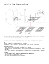
Place the Fireplace on the platform and install the Vent pipe. Next, connect the Gas line, and provide a gas service shut-o valve; according to local
gas codes. Before fastening in place line up the front face of the replace. Then secure in place with 1/4" lag bolts to the platform.
Place the Fireplace on the platform and install the Vent pipe. Next, connect the Gas line, and provide a gas service shut-o valve; according to local
gas codes. Before fastening in place line up the front face of the replace. Then secure in place with 1/4" lag bolts to the platform.
Installing the Single Sided Fireplace
Installing the See Through Fireplace
Figure 6.b Installing the Single Sided Fireplace
Figure 7.b Installing the Single Sided Fireplace
Figure 6. Stando Installation
Figure 7. Stando Installation

XG0221 13
Installation
AssembleNonCombustibleFramingD/DL6315/ST(Detail)
Model Supplied Steel Header Parts Installed Steel Header Measurements
D/DL6315
Non-Combustible stud, Horizontal QTY.4
16
11
/
16
" x 79
1
/
2
"Non-Combustible stud, Vertical QTY.3
Non-Combustible Stud Connector QTY.2
DL6315ST
Non-Combustible stud, Horizontal QTY.8
16
11
/
16
" x 79
1
/
2
"Non-Combustible stud, Vertical QTY.6
Non-Combustible Stud Connector QTY.4
272
10
11
16
"
130
5
1
8
"
764
30
1
16
"
130
5
1
8
"
1
2
2 2
1
11
3
3
424
16
11
16
"
3
3
REVISIONS
REV.
DESCRIPTION
DATE
CHANGED BY
-
.
- -
ITEM
NO.
PART NUMBER
DESCRIPTION
QTY.
1
DL63190-20
Non-Combustible stud,
Horizontal
4
2
DL63192-20
Non-Combustible stud, Vertical
3
3
DL63189-20
Non-Combustible Stud
Connector
2
1:16
DWG. NO.
SHEET 1 OF 1
WEIGHT:
DL63-Non Combustible Framing Assembly
Finish
MATERIAL
DIMENSIONS ARE IN INCHES
TOLERANCES:
FRACTIONAL
1/16"
TWO PLACE DECIMAL
.015"
THREE PLACE DECIMAL
.005"
ANGULAR
.5
ALL BENDS ARE ASSUMED
TO BE 90
UNLESS NOTED
OTHERWISE.
Revision / Date
Drawn by
DATE
NAME
06/10/2016
20 GA Satin
THE INFORMATION CONTAINED IN THIS DRAWING IS THE SOLE PROPERTY OF CANADIAN HEATING PRODUCTS. ANY REPRODUCTION IN PART OR AS A WHOLE WITHOUT THE WRITTEN PERMISSION OF CANADIAN HEATING PRODUCTS IS PROHIBITED.
PROPRIETARY AND CONFIDENTIAL
Y:\Products\Residential Products\R&D Projects\DL63\Cad Drawings\DL63-Non Combustible Framing Assembly
November-25-16 1:04:49 PM
SCALE
DM
Description
Non Combustible Framing
Revision
Assemble the frame using 1/4'' self tapping screws (supplied)
Figure 8. Assembly of Non Combustible Framing

XG022114
Installation
FramingBoxAssemblySingleSided
FramingBoxAssemblySee-Through
Figure 8. Framing Box Assembly Single Sided Figure 8.b Framing Box Assembly See-Through
†Mesurement is a 2x4 on side
and a 3/4'' plywood platform.
†Mesurement is a 2x4 on side
and a 3/4'' plywood platform.
D6315ST
A 18 7/16''
B 89 ½''
C 79 ½''
D 50 ⅜''
E 72''
F 18 7/16''
G 50 ⅜''
H 18 7/16''
I 79 ½''
J 72''
K
†
2 1/4''
D6315
A 21 ½''
B 89 ½''
C 79 ½''
D 50 ⅜''
E 72''
F 18''
G 50 ⅜''
H 18''
I 79 ½''
J 72''
K
†
2 1/4''
J
J
G
G
H
H
I
I
E
K
K
E
F
F
D
D
C
C
B
B
A
A

XG0221 15
Installation
FramingwithCoolWallAdvantage
TV recess framing
Figure 8.b.b Framing with Cool Wall Advantage
Figure 8.b.c Cool Wall Advantage vent dimensions
Figure 8.b.d Cool Wall Advantage TV recess dimensions
Below are basic instructions on the framing of the Cool Wall advantage kit. More detailed instructions including the installation diagrams are
included with the kit.
The recess must be made from Non-Combustable materials. Recess can
be increased beyond a 4" depth by using a 45° or 90° elbow in venting
after the minimum 3' upward distance is achieved, 1" clearance from
venting to combustibles must still be maintained.
1/32
.015
.005
1
UNLESS OTHERWISE SPECIFIED
ALL BENDS ARE 90
DIM ARE IN INCHES
FRACTIONAL
X.XX
X.XXX
ANGULAR:
NAME
CHECKED
DRAWN
THIRD ANGLE PROJECTION
DATE
FINISH
MATERIAL
WEIGHT (lbs)
BEND ALLOW.
K-FACTOR
38" Min
To Cool Wall
3" min
to Ceiling
2015.73
79.4
Steel Studs
2x4 On Edge
5" Dia Flex Vent
Main Vent
1:32
DWG. NO.
REV.
1 OF 2
THE INFORMATION CONTAINED IN THIS DRAWING IS THE SOLE PROPERTY OF CANADIAN HEATING PRODUCTS. ANY REPRODUCTION IN PART OR AS A WHOLE WITHOUT THE WRITTEN PERMISSION OF CANADIAN HEATING PRODUCTS IS PROHIBITED.
PROPRIETARY AND CONFIDENTIAL
June-10-19 12:47:54 PM
SCALE:
TV Kit Framing
SHEET:
SIZE
CF
26/05/2017
CF
1/19/2017
Y:\Products\Residential Products\R&D Projects\DL63\Cad Drawings\Manual\Y:\Products\Residential Products\R&D Projects\DL63\Cad Drawings\Distinction SHow Unit\TV Kit Framing
1/32
.015
.005
1
UNLESS OTHERWISE SPECIFIED
ALL BENDS ARE 90
DIM ARE IN INCHES
FRACTIONAL
X.XX
X.XXX
ANGULAR:
NAME
CHECKED
DRAWN
THIRD ANGLE PROJECTION
DATE
FINISH
MATERIAL
WEIGHT (lbs)
BEND ALLOW.
K-FACTOR
76mm
3"
Standoff
38mm
1
1
2
"
Standoff
52mm
2"
Opening
1653mm
65
1
16
"
Opening
778mm
30
5
8
"
Approximate Dimension
1677.92mm
66
1
16
"
5" Flex Vent Collars
Stabilizers
160mm
6
5
16
"
531mm
20
15
16
"
236mm
9
5
16
"
12.7mm
1
2
"
1:16
DWG. NO.
REV.
1 OF 2
A
THE INFORMATION CONTAINED IN THIS DRAWING IS THE SOLE PROPERTY OF CANADIAN HEATING PRODUCTS. ANY REPRODUCTION IN PART OR AS A WHOLE WITHOUT THE WRITTEN PERMISSION OF CANADIAN HEATING PRODUCTS IS PROHIBITED.
PROPRIETARY AND CONFIDENTIAL
June-21-18 12:25:45 PM
SCALE:
DL63 Heat Distribution TV Kit
DL63-Heat distribution TV kit
SHEET:
SIZE
A
CF
26/05/2017
CF
1/19/2017
Y:\Products\Residential Products\R&D Projects\DL63\Cad Drawings\Manual\Y:\Products\Residential Products\R&D Projects\DL63\Cad Drawings\DL63-Heat distribution TV kit for manual
4" Max
Depth
The recess MUST
be made from
Non-Combustable
materials. Maintain
1" clearance
from venting to
combustibles.
12" min. from
replace opening
3" Min. from
ceiling
TV RECESS

XG022116
Installation
Figure 8.b.b Included Restrictor plates
Figure 8.b.c Restrictor plate Installation
Restrictor plate Installation
Under no circumstances can Montigo ex venting be cut to
accommodate an installation. Use an alternative length to complete
your vent run.
NOTICE
Section 3: Venting
The termination location MUST be selected such that it is the highest
point in the venting assembly. It should also be selected such that it
provides the shortest vent run possible. Should it be impossible to ensure
that the termination is the highest point or should it be impossible to
meet the venting guidelines laid out below please contact your Montigo
dealer to discuss power venting options.
Notes For Planning Venting:
Included Restrictor plates:
1" Bae
1.5" Bae
1.75" Bae
The distinction is supplied with 3 dierent sized restrictor plates to
improve ame eciency. The size of restrictor used largely depends
on the number of elbows used in the vent run, as well as vertical rise.
Lengthy vertical runs without elbows would generally require the 1.75''
restrictor. Shorter runs, or multi elbow installations would use the 1.5''
or the 1'' restrictor.
• Venting originates from the top of the unit.
• Venting can terminate through the roof or exterior wall.
• For a detailed diagram of allowed termination locations, see
Appendix A.
• Once the termination location has been established refer to the
appropriate section for installation details.
• For Heat Shield requirements see Section 3-3-3.
Install Restrictor plate over the vent opening from inside the rebox
with two tek screws (supplied) into the rebox ceiling.

XG0221 17
Installation
Vertical Termination - 2 Elbows
Vertical Termination VerticalTermination-2Elbows
Vertical Termination
Figure 8. Vertical Termination Figure 8.b Vertical Termination - 2 Elbows
*Restrictor may be required
If the vent rise is over 8ft straight vertical, a restrictor must be installed.
We recommend using the 1.75” wide restrictor. If 1.75'' is too restrictive,
a 1.5'' and 1'' restrictor is also supplied.
NOTE: If using a restrictor, use an IR gun to measure the glass
temperature after 1 hour of running, and ensure the glass temperature
does not exceed 470°F and ensure that none of the media and no part
of the door has discoloured.
*Minimum 24'' from top of unit before attaching an elbow
V1
V1
H1
V2
Section 3-3-1: Venting Layouts
D6315, D6315ST, DL6315, DL6315ST
Vertical Minimum Vertical Maximum
3 FT 32 FT
D6315ST, DL6315ST
Vertical
Minimum
V1+V2
Horizontal
Maximum
H1
2 FT 3 FT
3 FT 6 FT
4 FT 9 FT
5 FT 12 FT
6 FT 15 FT
7 FT 18 FT
8 FT 21 FT
D6315, DL6315
Vertical
Minimum
V1+V2
Horizontal
Maximum
H1
2 FT 1 FT
3 FT 4 FT
4 FT 7.5 FT
5 FT 11 FT
6 FT 14 FT
7 FT 17.5 FT
8 FT 21 FT

XG022118
Installation
VerticalTermination-3Elbows
Figure 8.c Vertical Termination - 3 Elbows Figure 8.d Horizontal Termination - 1 Elbow
Horizontal Termination - 1 Elbow
Vertical Termination - 3 Elbows
V1
V1
V2
H1
H1
H2
D6315ST, DL6315ST
Vertical
Minimum
V1+V2
Horizontal
Maximum
H1+H2
2 FT 3 FT
3 FT 6 FT
4 FT 9 FT
5 FT 12 FT
6 FT 15 FT
7 FT 18 FT
8 FT 21 FT
D6315ST, DL6315ST
Vertical
Minimum
V1
Horizontal
Maximum
H1
2 FT 3 FT
3 FT 6 FT
4 FT 9 FT
5 FT 12 FT
6 FT 15 FT
7 FT 18 FT
8 FT 21 FT
D6315, DL6315
Vertical
Minimum
V1+V2
Horizontal
Maximum
H1+H2
2 FT 1 FT
3 FT 4 FT
4 FT 7.5 FT
5 FT 11 FT
6 FT 14 FT
7 FT 17.5 FT
8 FT 21 FT
D6315, DL6315
Vertical
Minimum
V1
Horizontal
Maximum
H1
2 FT 1 FT
3 FT 4 FT
4 FT 7.5 FT
5 FT 11 FT
6 FT 14 FT
7 FT 17.5 FT
8 FT 21 FT
HorizontalTermination-1Elbow
*Minimum 24'' from top of unit before attaching an elbow *Minimum 24'' from top of unit before attaching an elbow

XG0221 19
Installation
Figure 8.e Horizontal Termination - 2 Elbows
HorizontalTermination-2Elbows
Horizontal Termination - 2 Elbows
V1
H1
H2
D6315ST, DL6315ST
Vertical
Minimum
V1
Horizontal
Maximum
H1+H2
2 FT 3 FT
3 FT 6 FT
4 FT 9 FT
5 FT 12 FT
6 FT 15 FT
7 FT 18 FT
8 FT 21 FT
D6315, DL6315
Vertical
Minimum
V1
Horizontal
Maximum
H1+H2
2 FT 1 FT
3 FT 4 FT
4 FT 7.5 FT
5 FT 11 FT
6 FT 14 FT
7 FT 17.5 FT
8 FT 21 FT
*Minimum 24'' from top of unit before attaching an elbow

XG022120
Installation
Figure 8.f Horizontal Termination - 3 Elbows
HorizontalTermination-3Elbows
Horizontal Termination - 3 Elbows
V1
V2
H1
H2
D6315ST, DL6315ST
Vertical
Minimum
V1+V2
Horizontal
Maximum
H1+H2
2 FT 3 FT
3 FT 6 FT
4 FT 9 FT
5 FT 12 FT
6 FT 15 FT
7 FT 18 FT
8 FT 21 FT
D6315, DL6315
Vertical
Minimum
V1+V2
Horizontal
Maximum
H1+H2
2 FT 1 FT
3 FT 4 FT
4 FT 7.5 FT
5 FT 11 FT
6 FT 14 FT
7 FT 17.5 FT
8 FT 21 FT
*Minimum 24'' from top of unit before attaching an elbow
/