
“Waverley”
Inset Tray
DECORATIVE FUEL EFFECT GAS FIRE
THIS PRODUCT IS NOT SUITABLE FOR
PRIMARY HEATING PURPOSES
Installation, Maintenance & User Instructions
Hand these instructions to the user
Model No. FITC00MN is for use on Natural Gas (G20) at a supply
pressure of 20 mbar in G.B. / I.E.

CONTENTS
Section 1 Information and Requirements PAGE
1.0 Appliance Information 3
1
.1 Conditions of Installation 4
1.2 Flue and chimney suitability 4
1
.3 Fireplace / surround suitability 5
1.4 Shelf position 5
1
.5 Chimney inspection 5
1
.6 Fire place opening / catchment space 6
1.7 Hearths 7
1.8 Fitting to Chair bricks 8
1.9 Metal Flue boxes 8
1.10 Spillage Monitoring System 8
Section 2 Installation of Fire
2.1 Unpacking the fire 9
2.2 Installing the fire box 9-11
2.3 Gas tightness and Inlet pressure 11
Section 3 Assembling Fuel Bed and Commissioning
3.1 Assembling the ceramics and fuel bed 12-15
3.2 Lighting the appliance 15
3.3 Checking for clearance of combustion 16
products
Section 4 Maintenance
4.1 Removal of the Burner Assembly 17
4.2 Removal of the Piezo Igniter 17
4.3 Removal of the Control Tap 18
4.4 Removal of the Oxypilot 18
Section 5 User Instructions Section
5.1 Conditions of Installation / About Your New Gas Fire 19
5.2 Operating the Fire 20
5.3 Cleaning the Fire 21
5.4 Replacing the fuel-bed and ceramics 22-25
This appliance is manufactured by :-
BFM Europe Ltd.
Trentham Lakes,
Stoke-on-Trent,
ST4 4TJ
2

SECTION 1
INFORMATION AND REQUIREMENTS
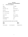
1.0 APPLIANCE INFORMATION
Model FITC00MN
Gas Type G20
Main injector (1 off) Size 420 Cat 82
Pilot Type Copreci 21100 / 141
Max. Gross Heat Input : 6.9 kW
Min. Gross Heat Input : 4.0 kW
Cold Pressure : 20.0 +/-1.0 mbar
Ignition : Push-button Piezo
Electrode Spark Gap 4.0mm
Packed Weight 6kg
Inset Tray Dimensions (with ceramic & coals fitted)
Width : 380mm
Height : 320mm
Depth : 230mm
Gas Connection : 8mm Compression (Supplied with fire)
3

INSTALLATION REQUIREMENTS
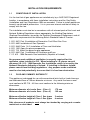
1.1 CONDITIONS OF INSTALLATION
It is the law that all gas appliances are installed only by a GAS SAFE Registered
Installer, in accordance with these installation instructions and the Gas Safety
(Installation and Use) Regulations 1998 as amended. Failure to install appliances
correctly could lead to prosecution. It is in your own interest and that of safety to
comply with the law.
The installation must also be in accordance with all relevant parts of the Local and
National Building Regulations where appropriate, the Building Regulations
(Scotland Consolidation) issued by the Scottish Development Department, and all
applicable requirements of the following British Standard Code of Practice.
1. B.S. 5871 Part 3 Installation of Decorative Fuel Effect Gas Fires
2. B.S. 6891 Installation of Gas Pipework
3. B.S. 5440 Parts 1 & 2 Installation of Flues and Ventilation
4. B.S. 1251 Open fire place components
5. B.S. 715 Metal flue pipes for gas appliances
6. B.S. 6461 Part 1 Installation of Chimneys and flues
7. I.S. 813 : 1996 Domestic Gas Installation (Republic of Ireland)
No purpose made additional ventilation is normally required for this
appliance, when installed in G.B. When Installing in I.E. please consult
document I.S. 813 : 1996 Domestic Gas Installation, which is issued by the
National Standards Authority of Ireland. If installing in Northern Ireland,
please consult local building regulations. Any purpose made ventilation
must be checked periodically to ensure that it is free from obstruction.
1.2 FLUE AND CHIMNEY SUITABILITY
This appliance is designed for use with conventional brick built or lined chimneys
and fabricated flues of 125mm diameter minimum. Any metal flue boxes used
must conform to BS 715. All flues must conform to the following minimum
dimensions.
Minimum diameter of circular flues (Class 1) 175 mm
Minimum diameter of circular flues (Class 2) 125 mm
Minimum effective height of Class 1 flue types 3 metres
Minimum effective height of Class 2 flue types 4 metres
Safe clearance of products must
always be checked by carrying out a smoke
match test as described.
4

1.3 FIREPLACE / SURROUND SUITABILITY
The fire must only be installed on a hearth it must not be installed directly onto
carpet or other combustible floor materials.
The fire is suitable for fitting to non-combustible fire place surrounds and
proprietary fire place surrounds with a temperature rating of at least 150
o
c.
If a heating appliance is fitted directly against a wall without the use of a fire
surround or fire place all combustible material must be removed from behind
the trim. Soft wall coverings such as blown vinyl, wall paper etc. could be
affected by the rising hot air and scorching and/or discoloration may result.
Due consideration should be made to this when installing or decorating.
1.4 SHELF POSITION
The fire may be fitted below a combustible shelf providing there is a minimum
distance of 200mm above the top of the fire and the shelf does not project more
than 150mm. If the shelf overhangs more than 150mm the distance between the
fire and the shelf must be increased by 15mm for every 25mm of additional
overhang over 150mm.
1.5 FLUE / CHIMNEY INSPECTION
Before commencing installation, a flue or chimney should be inspected to ensure
that all the following conditions are satisfied.
1. Check that the chimney / flue only serves one fire place and is clear of any
obstruction. Any dampers or register plates, other than those supplied on
the cast front must be removed or locked in the open position.
2. Brick/stone built chimneys or any chimney or flue which has been used for
an appliance burning fuel other than gas must be thoroughly swept. The
base of the chimney / flue must also be thoroughly cleared of debris etc.
3. Any under-floor air supply to the fire place must be completely sealed off.
4. Ensure that the inside of the chimney / flue is in good condition along it’s
length and check that there is no leakage of smoke through the structure
of the chimney during and after the smoke pellet test.
5. Using a smoke pellet, check that there is an up-draught in the
chimney / flue and that the smoke can be seen issuing from the
terminal / chimney pot outside.
There must be no leakage of smoke through the structure of
the chimney during or after the smoke pellet test and it is
important to check inside upstairs rooms adjacent to the chimney /
flue.
5

Check the chimney pot / terminal and general condition of the
brickwork or masonry. If the chimney or flue is in poor condition or if
there is no up-draught do not proceed with the installation. If there is a
history of down-draught conditions with the chimney / flue, a tested and
certificated flue terminal or cowl suitable for the relevant flue type should
be considered.
6. A spillage test must always be carried out during commissioning of
the appliance.
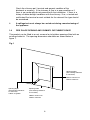
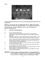
1.6 FIRE PLACE OPENING AND CHIMNEY CATCHMENT SPACE
This product can be fitted to a cast surround or to builders openings fitted with an
existing chairbrick. The opening dimensions should be as shown below in
figure 1.
Fig. 1
6
Opening width
(with existing chairbrick
or cast back)
400mm minimum to
480mm maximum
Opening height
(with existing chairbrick
or cast back)
550mm minimum to
720mm maximum
Opening depth
(with existing chairbrick
or cast back)
230mm or greater

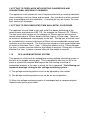
1.7 HEARTHS
This appliance must only be installed on to a concrete or non-combustible hearth.
The hearth material must be a minimum thickness of 12mm with the top surface at
least 50mm above the floor. The hearth must be fitted symmetrically about the fire
opening and have a minimum width of 760mm and a minimum projection of
300mm forwards from the fire opening. See figure 2 below.
Fig. 2
7
300mm minimum
760mm minimum
Minimum
thickness 12mm
with top surface
50mm above
floor level

1.8 FITTING TO FIREPLACES WITH EXISTING CHAIRBRICKS AND
CONVENTIONAL BRICKBUILT CHIMNEYS
This appliance is not suitable for use in fireplaces fitted with an existing chairbrick,
when installing a cast iron fascia and surround. Any chairbrick must be removed
prior to proceeding with the installation. If installing the tray on its own, the chair-
brick can be left in position.
1.9 FITTING TO PRE-FABRICATED TWIN WALL METAL FLUE BOXES
The appliance may be fitted to twin wall metal flue boxes conforming to the
constructional requirements of BS 715, (for example the Ritevent LFE 175 box).
The box must have a minimum flue diameter of 125mm internal and minimum
internal dimensions of 300mm deep by 580mm high by 470mm wide. There are
no maximum dimensional requirements for the box. The top face of the box must
be insulated with a minimum thickness of 50mm of non-combustible mineral wool
insulation or similar material. The flue box must stand on a non-combustible base
of minimum thickness 12mm. Note : If fitting this product with a 175mm diameter
flue liner, 3 metres minimum effective flue height is required, if fitting with a 125mm
diameter flue liner, 4 metres minimum effective flue height is required.
1.10 SPILLAGE MONITORING SYSTEM
This appliance is fitted with an atmosphere sensing spillage monitoring system in
the form of an oxygen sensing pilot. This is designed to shut the fire off in the
event of a partial or complete blockage of the flue causing a build up of
combustion products in the room in which the fire is operated. The following are
important warnings relating to this spillage monitoring system :-
1) The spillage monitoring system must not be adjusted by the installer.
2) The spillage monitoring system must not be put out of operation.
3) When the spillage monitoring system is exchanged only a complete original
manufacturers part may be fitted.
8

SECTION 2
INSTALLATION OF FIRE
2.1 UNPACKING THE FIRE
Carefully lift the fire out of the carton. Remove the loose item packaging carefully
from the front of the appliance. Check the contents as listed :-
Packing Check List - Coal Fuelbed Models
1off Fire tray / burner assembly
1off Boxed ceramic base, L/H & R/H ceramic front rails plus coals
1off Coals bag, containing, 3 medium square coals, 2 small square, 11
small coals & 7 large coals - total of 23 coals packed in ceramics box
1off Loose items bag.
1off Installation / User book (Combined)
2.2 INSTALLING THE TRAY
Establish which type of flue you are intending to install the fire in to :-
225 x 225mm (9 inch x 9 inch) brick built chimneys
175mm (7 inch) diameter lined brick or stone flue, or insulated pre-fabricated
metal flue box to B.S. 715. (minimum effective flue height 3 metres)
125mm (5 inch) diameter brick or stone flue, or insulated pre-fabricated
metal flue box to B.S. 715. (minimum effective flue height 4 metres)
A spillage test must always be carried out to check satisfactory
clearance of flue products, regardless of the type of flue the
appliance is being fitted to.
To Install the Fire Proceed as follows :-
a) Carefully place the burner tray in the chairbrick opening or cast fascia.
b) Mark the centres of the two fixing holes, which are located in the
front flange, below the control knob / piezo button on the burner tray.
c) Whilst the fire is in position, decide which side the gas supply is to enter
the fire from and plan accordingly. The inlet elbow can be loosened and
rotated if necessary. See Fig. 3 & 4 overpage for suggested pipe routes.
9

Fig. 3 Gas Supply entering from RHS
Fig. 4 Gas Supply entering from LHS
d) Carefully withdraw the fire base from the opening to enable the gas
supply and fire fixing to be completed.
e) Drill 2 off fixing holes as marked out in section b) to accomodate 2 off
no. 10 or 12 rawl plugs
f) Fit the rawl plugs (supplied)
Cast Iron Fascia
Approx.
40mm
Fireplace
Gas Supply
Cast Iron Fascia
Approx.
40mm
Fireplace
Gas Supply
10

g) Making the gas connection
The gas connection should be made to the appliance inlet elbow using
rigid 8mm piping.
h) Lift the firebase in to position and secure the base of the fire opening
with the two screws provided, ensure when fitted that the fire tray sits
level.
i) Before making the final gas connection, thoroughly purge the gas
supply pipework to remove all foreign matter, otherwise serious damage
may be caused to the gas control valve on the fire.
NOTE :- Failure to correctly purge the pipework will invalidate the
guarantee
2.3 GAS TIGHTNESS AND INLET PRESSURE
a) Remove the pressure test point screw from the inlet elbow and fit a
manometer.
b) Turn on the main gas supply and carry out a gas tightness test.
c) Depress the control knob and turn anti-clockwise to the position marked
ignition / low. Hold in the control knob for a few seconds to purge the
pipe work then press the igniter button. The burner should light,
continue to hold the control knob for a few seconds then turn to the full-
on position.
d) Check that the gas pressure is 20.0 mbar (+/- 1.0mbar) 8.0 in w.g.(+/-
0.4 in w.g.) for Natural Gas Models
e) After removing the manometer, ensure that the pressure test point
screw is checked for gas tightness with suitable leak detection
spray or fluid.
11

SECTION 3
ASSEMBLING FUEL-BED AND COMMISSIONING
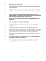
3.1 ASSEMBLING THE FUEL-BED
a) Position the two halves of the ceramic front rail onto the support as
shown below in Fig. 5
Fig. 5
b) Place the fuelbed base centrally on to the fuelbed support and push
fully backwards to the rear face of the cast iron back panel.
Make sure that the fuelbed base is located centrally on the burner
tray. See Fig. 6 below.
Fig. 6
12

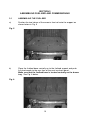
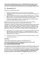
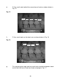
c) Fit three off medium and two off small square coals as shown in
position on the front ceramic rails, see Fig. 7 below.
Fig. 7
d) Fit five off large coals into the recess’s behind the front row of coals, as
shown below in Fig. 8
Fig. 8
13
SS
SS
M Square
M Square
M Square
Large
Large
Large
Large
Large

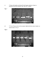
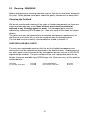
e) Fit five small coals behind the second row of coals as shown below in
Fig. 9
Fig. 9
f) Fit four small coals on the back row as shown below in Fig. 10
Fig. 10
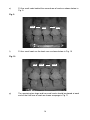
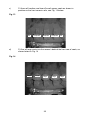
g) The remaining two large and two small coals should be placed at each
end of the third row of coals as shown overpage in Fig. 11
14
Small
Small
Small
S
mall
S
mall
Small
Small
Small
Small

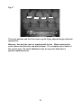
Fig. 11
The exact position and fit of the coals may be finely adjusted to give the best
appearance.
Warning : Use only the coal set supplied with the fire. When replacing the
coals remove the old coals and discard them. Fit a complete set of coals of
the correct type. Do not fit additional coals or any coals other than a
genuine replacement set.
3.2 LIGHTING THE APPLIANCE
a) Turn on the gas isolation tap.
b) Depress the control knob and turn anti-clockwise to the position
marked pilot. Hold in the control knob for a few seconds to purge the
pipe work.
c) Continue to hold-in the control knob and press the igniter button. If the
burner does not light, continue to press the igniter button until ignition
occurs. Continue to hold the control knob for 5-10 seconds to allow the
thermocouple to heat up, if the pilot goes out when the control knob is
released, repeat the lighting sequence.
d) Turn the control knob in the anti-clockwise direction to the high position
and the main burner will light.
e) Turn the control knob clockwise to the low position and the gas input
will be reduced to the minimum setting.
f) Slightly depress the control knob and turn to the pilot position, the main
burner will go out but the pilot will remain lit.
g) Slightly depress the control knob and turn to the off position, the pilot
will now be extinguished.
WARNING : If the fire goes out for any reason or is turned off and it
is necessary to re-light the fire it is important to allow the
fire to cool for 3 minutes before attempting to re-light it
15
Large
Small
L
arge
Small

3.3 CHECKING FOR CLEARANCE OF COMBUSTION PRODUCTS
a) Close all doors and windows in the room.
b) Light the fire and allow to run for approximately 5 minutes on high
position.
c) After approximately 5 minutes hold a smoke match just inside and
below the centre of the lower front edge of the top of the fire. (It is
recommended that a suitable smoke match holder is used when check
ing for clearance of combustion products). All smoke generated should
be drawn back into the flue. If slight spillage occurs or if in doubt,
repeat the test after a further 5-10 minutes.
d) If spillage persists, the flue is not functioning correctly and a fault exists.
If, after investigation the fault cannot be traced and rectified, the fire
must be disconnected from the gas supply and expert advice obtained.
e) If there is an extractor fan fitted any where in the vicinity of the
appliance, or in adjacent rooms the spillage test should be repeated
with the fan running on maximum and all interconnecting doors open.
f) After ensuring that the fire is safe to use it should be left on high
position to fully warm up. During this time a slight odour may be
noticed, this is due to the “newness” of the fire and will soon disappear.
At this stage any minor adjustments to the coals should be made
using suitable long handled tongs and taking care not to damage the
coals.
Finally, hand the Installation and Maintenance Instructions and the
Users Instructions over to the customer and explain the operation of the
fire.
16

SECTION 4
MAINTENANCE
Servicing Notes
Servicing should be carried out annually by a competent person such as a GAS
SAFE registered engineer. This is a condition of the Flavel guarantee
schemes.
The service should include visually checking the chimney and fire opening for
accumulations of debris and a smoke test to check for a positive up-draught in the
chimney.
The condition of the coals should be checked and if necessary the whole set
should be replaced with a genuine replacement set.
The burner assembly is designed to be removed as a complete unit for ease of
access. After any servicing work a gas tightness check must always be
carried out. All sections apply for coal fuelbed model variants.
For Diagrams refer to Section 2
4.1 Removing the burner assembly from the fire.
4.1.1 Prepare work area (lay down dust sheets etc.)
4.1.2 Remove the front bars / ash pan cover and put them in a safe
location. Remove the loose coals from the fuel bed. Remove the
fuelbed matrix & ceramic front rails.
4.1.3 Isolate the gas supply and remove the inlet pipe from the appliance
inlet elbow. Unscrew and remove the two screws which retain the
burner at the base. Remove the burner assembly from the fire.
4.1.4 To refit the burner assembly. Push the burner to locate against the rear
panel of the cast and secure the burner at the base of the control panel
with two screws. Refit the gas supply pipe and carry out a gas
tightness test. The ash pan cover and front bars can now be re-
positioned.
4.2 Removing the Piezo Igniter
4.2.1 Remove the burner assembly as in section 4.1
4.2.2 Disconnect the ignition lead from the piezo and unscrew the
retaining nut on the rear of the control panel. Withdraw the piezo from
the front of the control panel. Re-assemble in reverse order and carry
out a gas tightness test. Ensure the heatshield is re-fitted.
4.3 Removing the Control Tap from the fire.
17

4.3.1 Remove the burner assembly as in section 4.1.
4.3.2 Pull the control knob off the control tap spindle.
4.3.3 Loosen and remove the two gas pipe retaining nuts from the control
tap and release the ends of the gas pipes from the control tap body.
Remove the screw in thermocouple from the end of the control tap.
4.3.4 Unscrew the control tap locknut from the front of the control panel and
remove the control tap.
4.3.5 To refit a control tap, reassemble in reverse order noting that the control
tap locates with a flat in the control panel. Carry out a gas tightness
test after re-assembly.
4.4 Removing the Oxy-Pilot Assembly
Note : Because this appliance is fitted with an atmosphere sensing ‘Oxy-
Pilot’ it is not possible to replace the thermocouple separately, because the
thermocouple position is factory set to a tight tolerance. Any replacement of
parts on the pilot requires a complete new pilot assembly.
4.4.1 Remove the burner assembly as in section 4.1
4.4.2 Remove the burner heat shield which is held in position by 2 screws.
4.4.3 Unscrew and remove the thermocouple retaining nut from the end of the
control tap and disconnect the ignition lead from the pilot electrode.
4.4.4 Unscrew and remove the two pozi-driv screws which secure the pilot
assembly to the burner. Remove the pilot.
4.4.5 Re-assemble in reverse order and carry out a gas tightness test.
PARTS SHORTLIST
Replacement of any other parts must be carried out by a competent person such
as a GAS SAFE registered gas installer. The part numbers of the main replace-
able parts are as follows, these are available from Flavel. (see rear page for con-
tact details)
Coal Pack B-87350 Coal Fuelbed Matrix B-87340
L/H Ceramic Front Rail B-87300 R/H Ceramic Front Rail B-87310
Gas Valve SP-10688
Piezo Igniter B-1320
Ignition Wire B-39030
18

SECTION FIVE - USER INSTRUCTIONS
5.1 About your Flavel Waverley Inset Tray
The Flavel Waverley Inset Tray incorporates a unique and highly developed fuel
bed which gives the realism of a loose coal layout combined with realistic flames
and glow. The use of durable ceramic material in the construction of the fuel-bed
components ensures long and trouble free operation.
When first using the new fire a slight smell may be noticed. This is due to starch
used in the manufacture of the soft ceramic coals or pebbles, it is non-toxic and
will soon disappear.
Please take the time to fully read these instructions as you will then be able to
obtain the most effective and safe operation of your fire.
IMPORTANT SAFETY INFORMATION
WARNING
This appliance has a naked flame and as with all heating appliances a
fireguard should be used for the protection of children, the elderly and
infirm. Fireguards should conform to B.S. 8423 : 2002 (Fireguards for use
with gas heating appliances).
It is important that this appliance is serviced at least once a year by a GAS SAFE
registered gas installer and that during the service the fire is removed from the fire
opening and the chimney or flue visually checked for fallen debris or blockages
which must be removed. The chimney should also be checked to ensure
clearance of flue products. These are conditions of the manufacturers
guarantee. After installation or during servicing a spillage test must always
be carried out.
Rubbish of any type must NEVER be thrown onto the fuel-bed, this could affect
safe operation and damage the fire.
Any debris or deposits should be removed from the fuel-bed from time to time.
This may be carried out by referring to the cleaning section as described later in
this book.
Only the correct number and type of coals must be used and only
complete and genuine replacement sets must be sourced from BFM Europe Ltd.
Ltd (See rear cover of this book for contact details)
The appliance must only be used with the coal set supplied and must not be used
with other coals.
Always keep furniture and combustible materials well clear of the fire and never
dry clothing or items either on or near to the fire. Never use aerosols or
flammable cleaning products near to the fire when it is in use.
19

The ceramic fuel-bed remains hot for a considerable period after use and
sufficient time should be allowed for the fire to cool before cleaning etc.
The fire must only be operated with the cast surround supplied with the fire.
5.2 Operating the Fire
To light the fire proceed as follows:-
1) Depress the control knob and turn anti-clockwise to the position
marked pilot. Hold in the control knob for a few seconds to allow the gas to
reach the pilot.
2) Continue to hold-in the control knob and press the igniter button. If the pilot
does not light, continue to press the igniter button until ignition occurs. When
the pilot has lit, continue to hold the control knob in for 5-10 seconds
to allow the thermocouple to heat up, if the pilot goes out when the control
knob is released, repeat the lighting sequence.
In the unlikely event of a failure of the igniter, the fire can be lit as follows :-
Depress the control knob and turn anti-clockwise to the position
marked pilot. Hold in the control knob for a few seconds to allow the gas to reach
the pilot. Insert the tip of a lit taper in behind the front ceramic coals on the left
hand side. This will light the pilot flame. When the pilot has lit, continue to hold
the control knob in for 5-10 seconds to allow the thermocouple to heat up, if the
pilot goes out when the control knob is released, repeat the lighting sequence.
3) After lighting, turn the control knob in the anti-clockwise direction to the high
position and the main burner will light. It is recommended that for most
efficient performance the fire is allowed to warm up for a few minutes with
the gas control on maximum.
4) The gas control can be turned clockwise from the maximum position to give
the desired heat output.
WARNING
If the fire goes out for any reason or is turned off and it is
necessary to re-light the fire it is important to allow the fire to cool
for 3 minutes before attempting to re-light it.
SPILLAGE MONITORING SYSTEM
This appliance is fitted with a spillage monitoring system which shuts down the fire
if the evacuation of combustion products from the fire is affected by a partially or
fully blocked flue. If this system operates the fire will go out. If this occurs, leave
the fire for at least three minutes then follow the lighting procedure as described in
the previous section. In the event of repeated operation a GAS SAFE regis-
tered gas installer must be called to investigate and rectify the cause.
20
Page is loading ...
Page is loading ...
Page is loading ...
Page is loading ...
Page is loading ...
Page is loading ...
-
 1
1
-
 2
2
-
 3
3
-
 4
4
-
 5
5
-
 6
6
-
 7
7
-
 8
8
-
 9
9
-
 10
10
-
 11
11
-
 12
12
-
 13
13
-
 14
14
-
 15
15
-
 16
16
-
 17
17
-
 18
18
-
 19
19
-
 20
20
-
 21
21
-
 22
22
-
 23
23
-
 24
24
-
 25
25
-
 26
26


Flavelfires Decorative Flame Effect Gas Fire User manual
- Type
- User manual
- This manual is also suitable for
Ask a question and I''ll find the answer in the document
Finding information in a document is now easier with AI
Related papers
-
Flavel Finesse Gas Fire User manual
-
-
-
-
-
-
-
-
-
Other documents
-
-
-
-
-
-
-
 Kinder Black Magic Installation And Maintenance Instructions Manual
-
-
Vision V1/400/A Installation & User's Instructions
-
