Page is loading ...

USER GUIDE & SERVICE MANUAL
Outdoor Collection
●
UODR124
●
24” Drawer Refrigerator

USER GUIDE & SERVICE MANUAL
u-line.com
Table of Contents
Intro
Safety
Safety and Warning
Disposal And Recycling
Installation
Environmental Requirements
Electrical
Cutout & Product Dimensions
Anti-Tip Bracket
General Installation
Grille Installation
Drawers
Maintenance
Free Standing Kit
Cleaning
Cleaning Condenser
Extended Non-Use
Operating Instructions
First Use
Control Operation
Airflow and Product Loading
Service
Troubleshooting
Wire Diagram
Product Liability
Warranty Claims
Parts
Ordering Replacement Parts
R600a Specifications
System Diagnosis Guide
Compressor Specifications
Troubleshooting Extended
Control Operation - Service
Defrost
Remove Fan and Cover
Warranty

USER GUIDE
u-line.com
Introduction
WELCOME TO U-LINE
Congratulations on your U-Line purchase. Your product comes from a company with over ve decades of premium modular ice
making, refrigeration, and wine preservation experience. U-Line creates products focused on functionality, style, and inspired
innovations — paying close attention to even the smallest details. Applications include residential, outdoor, ADA height
compliant, marine, and commercial. Complete product categories include Beverage Centers, Wine Refrigerators, Ice Machines,
Refrigerators, Freezers, and Dispensers.
Our advanced refrigeration systems, large and exible capacities, and Built-In to Stand Out
®
clean integrated look allow you
to preserve the right product, in the right place, at the right temperature. Since 2014, U-Line has been part of the Middleby
family of brands. All products are designed, engineered, and assembled in Milwaukee, Wisconsin, USA, and select products
are available worldwide.
PRODUCT INFORMATION
Looking for additional information on your product? User Guides, Spec Sheets, CAD Drawings, Compliance Documentation,
and Product Warranty information are all available for reference and download at u-line.com.
PROPERTY DAMAGE / INJURY CONCERNS
In the unlikely event property damage or personal injury is suspected related to a U-Line product, please take the following
steps:
1. U-Line Customer Care must be contacted immediately at +1.414.354.0300.
2. Service or repairs performed on the unit without prior written approval from U-Line is not permitted. If the unit has been
altered or repaired in the eld without prior written approval from U-Line, claims will not be eligible.
GENERAL INQUIRIES
U-Line Corporation
8900 N. 55th Street
Milwaukee, Wisconsin 53223 USA
Monday - Friday 8:00 am to 4:30 pm CST
T: +1.414.354.0300
Email: sales@u-line.com
u-line.com
CONNECT WITH US
SERVICE & PARTS ASSISTANCE
Monday - Friday 8:00 am to 4:30 pm CST
T: +1.414.354.0300
Service Email: onlineservice@u-line.com
Parts Email: onlineparts@u-line.com
Designed, engineered and assembled in WI, USA
3

USER GUIDE
u-line.com
Safety and Warning
Safety and Warning
NOTICE
Please read all instructions before installing,
operating, or servicing the appliance.
Use this appliance for its intended purpose only and follow
these general precautions with those listed throughout this
guide:
SAFETY ALERT DEFINITIONS
Throughout this guide are safety items labeled with a
Danger, Warning, or Caution based on the risk type:
Danger means that failure to follow this safety
statement will result in severe personal injury or
death.
Warning means that failure to follow this safety
statement could result in serious personal injury
or death.
Caution means that failure to follow this safety
statement may result in minor or moderate
personal injury, property, or equipment damage.
This unit contains R600a (Isobutane) which is a
ammable hydrocarbon. It is safe for regular
use. Do not use sharp objects to expedite
defrosting. Do not service without consulting the
“R600a specications” section included in the
User Guide. Do not damage the refrigerant
circuit.
Service must be done by factory authorized
service personnel. Any parts shall be replaced
with like components. Failure to comply could
increase the risk of possible ignition due to
incorrect parts or improper service.
CALIFORNIA PROPOSITION 65
This product contains chemicals known to the
state of California to cause cancer and birth
defects or other reproductive harm.
www.P65warnings.CA.gov
This equipment is to be installed with adequate
backow protection to comply with applicable
federal, state and local codes.
DANGER
!
DANGER
!
WARNING
!
CAUTION
!
CAUTION
!
WARNING
!
4

USER GUIDE
u-line.com
Disposal and Recycling
Disposal and Recycling
RISK OF CHILD ENTRAPMENT. Before you throw
away your old refrigerator or freezer, take o
the doors and leave shelves in place so children
may not easily climb inside.
If the unit is being removed from service for disposal,
check and obey all federal, state, and local regulations
regarding the disposal and recycling of refrigeration
appliances, and follow these steps completely:
1. Remove all consumable contents from the unit.
2. Unplug the electrical cord from its socket.
3. Remove the door(s)/drawer(s).
DANGER
!
5

USER GUIDE
Environmental Requirements
u-line.com
Environmental Requirements
This unit is designed to operate between 50°F (10°C) and
100°F (38°C). Higher ambient temperatures may reduce
the unit’s ability to reach low temperatures and/or reduce
ice production on applicable models.
For best performance, keep the unit out of direct sunlight
and away from heat generating equipment.
In climates where high humidity and dew points are
present, condensation may appear on outside surfaces.
This is considered normal. The condensation will
evaporate when the humidity drops.
CAUTION
!
Damages caused by ambient temperatures of
40°F (4°C) or below are not covered by the
warranty.
6

USER GUIDE
Electrical
u-line.com
Electrical
WARNING
!
SHOCK HAZARD — Electrical Grounding
Required. Never attempt to repair or perform
maintenance on the unit until the electricity has
been disconnected.
Never remove the round grounding prong from
the plug and never use a two-prong grounding
adapter.
Altering, cutting or removing power cord,
removing power plug, or direct wiring can cause
serious injury, fire, loss of property and/or life,
and will void the warranty.
Never use an extension cord to connect power to
the unit.
Always keep your working area dry.
NOTICE
Electrical installation must observe all state and
local codes. This unit requires connection to a
grounded (three-prong), polarized receptacle
that has been placed by a qualified electrician.
The unit requires a grounded and polarized 115 VAC,
60 Hz, 15A power supply (normal household current). An
individual, properly grounded branch circuit or circuit
breaker is recommended. A GFCI (ground fault circuit
interrupter) is usually not required for fixed location
appliances and is not recommended for your unit because
it could be prone to nuisance tripping. However, be sure
to consult your local codes.
See CUTOUT & PRODUCT DIMENSIONS for recommended
receptacle location.
7

USER GUIDE
Cutout & Product Dimensions
u-line.com
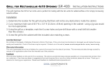
Cutout & Product Dimensions
PREPARE SITE
Your U-Line product has been designed for either free-
standing or built-in installation. When built-in, your unit
does not require additional air space for top, sides, or
rear. However, the front grille must NOT be obstructed,
and clearance is required for an electrical connection in
the rear.
CAUTION
!
Unit can NOT be installed behind a closed
cabinet door.
If you would like to align the face of the unit
with other adjacent cabinet doors, you may need
to alter the wall just behind the drain connection
on the unit to accommodate the drain.
CUTOUT DIMENSIONS
PRODUCT DIMENSIONS
REAR
4"
(102 mm)
7"
(178 mm)
24"
(610 mm)
24"
(610 mm)
34 ȟΞ"
(867 mm)
to
35 ȟΞ"
(892 mm)
Preferred location
for electrical outlet
is in adjacent
cabinet.
Α/Ξ"
(16 mm)
23 ⁄”
(608 mm)
23 ⁄”
(600 mm)
21 ⁄”
(548 mm)
15”
(381 mm)
15”
(381 mm)
3 ⁄”
(91 mm)
34”
to
35”
(864 mm to
889 mm)
TOP
FRONT
SIDE
⁄
”
(6 mm)
25 ⁄”
(637 mm
10 ⁄”
(273 mm
17”
(432 mm
11 ⁄”
(295 mm
7 ⁄”
(184 mm
1”
(25 mm
23 ⁄”
(591 mm
18 /”
(476 mm)
41
⁄”
(1046 mm)
9 ⁄”
(240 mm)
20
⁄”
(581 mm)
Power Cord
6 ft (183 cm)
6 ⁄”
(162 mm)
3 ⁄”
(98 mm)
8

USER GUIDE
u-line.com
Anti-Tip Bracket
Anti-Tip Bracket
1. Slide unit out so screws on top of unit are easily
accessible.
2. Remove the two screws from the opposite side of the
hinge assembly using a T-25 Torx driver (see below).
NOTE: 24” models use four screws and 15” models
use three screws, but same screws are used in both
applications.
3. Place bracket over holes and attach to unit with two
screws removed in step 2 using a T-25 Torx driver.
Tighten screws fully.
4. Gently push unit into position. Be careful not to
entangle the electrical cord or water line, if applicable.
5. Check to be sure the unit is level from front to back
and side to side. Make any necessary adjustments.
The unit’s top surface should be approximately ”
(3 mm) below the countertop.
6. Secure bracket into adjoining surface.
FLOOR MOUNTED ANTI-TIP INSTALLATION
1. Locate two anti-tip brackets included with the kit.
2. Place the unit into the area where it will be installed.
test to make sure the door opens and closes freely.
3.
center of the unit.
4. Remove the unit. Using a square, extend center line
“B” (see chart below). This line serves as the back
edge for the anti-tip brackets. From the center line,
edge of each bracket.
C
L
Back wall
Back of unit
Front of unit
Surrounding
area (Top view)
A
A
B
024/124 115
A 11-” (281 mm) 6-” (167 mm)
B 20-” (514 mm) 20-” (514 mm)
5.
drawn for the outer edge. Mark spots for the screw
holes.
C
L
Surrounding
area (Top view)
Drill holes and
mount anti-tip
brackets to floor
Back wall
Front
of
unit
Back
of
unit
A
A
B
024/124 115
A 11-” (281 mm) 6-” (167 mm)
B 20-” (514 mm) 20-” (514 mm)
6. Use a 1/8” drill to make two starter holes and fasten
provided.
7. Place the unit back into position, making sure the
feet engage the anti-tip brackets properly. Check
3 with the position of the front feet to ensure proper
positioning.
9

USER GUIDE
u-line.com
General Installation
General Installation
LEVELING INFORMATION
1. Use a level to
conrm the unit is
level. Level should
be placed along top
edge and side edge
as shown.
2. If the unit is not level, adjust the legs on the corners of
the unit as necessary.
3. Conrm the unit is level after each adjustment and
repeat the previous steps as needed.
INSTALLATION TIP
If the room oor is higher than the oor in the cutout
opening, adjust the rear legs to achieve a total unit rear
height of
1⁄8” (3 mm) less than opening’s rear height.
Shorten the unit height in the front by adjusting the front
legs. This allows the unit to be gently tipped into the
opening. Readjust the front legs to level the unit after it is
correctly positioned in the opening.
INSTALLATION
1. Plug in the power/electrical cord.
2. Gently push the unit into position. Be careful not
to entangle the cord or water and drain lines, if
applicable.
3. Re-check the leveling, from front to back and side to
side. Make any necessary adjustments. The unit’s top
surface should be approximately
1⁄8” (3 mm) below
the countertop.
4. Install the anti-tip bracket.
5. Remove interior packing material and wipe out the
inside of the unit with a clean, water-dampened cloth.
1
Turn to Adjust
10

USER GUIDE
u-line.com
Grille Installation
Grille Installation
REMOVING AND INSTALLING GRILLE
Disconnect electric power to the unit before
removing the grille.
When using the unit, the grille must be installed.
DO NOT touch the condenser ns. The condenser
ns are SHARP and can be easily damaged.
Removing the grille
1. Disconnect power to the unit.
2. Loosen the two screws (1).
3. Remove grille (2) from unit.
Installing the grille
1. Align cabinet and grille holes and secure, but do not
over tighten grille screws (1).
Note: When installing next to a 15” wide U-Line
product, use the supplied spacers behind the
grille. The 24” grille will now be on the same
plane as the 15” grille.
2. Reconnect power to the unit.
WARNING
!
WARNING
!
2
1
11

USER GUIDE
Drawers
u-line.com
Drawers
CHECKING DRAWER ALIGNMENT
The unit’s drawers are aligned at the factory before
shipment. However, their alignment could have been
disturbed during shipment or during overlay panel
installation. Check each drawer to confirm that it is
aligned:
•
Side-to-Side — When viewed from the top, the
drawer front should be square with the sides of the
cabinet.
•
Front-to-Back — When viewed from the side, the
drawer front should be straight with the cabinet’s sides,
not cocked forward or back.
•
Top-to-Bottom — When viewed from the front, the
drawer should be level horizontally.
ADJUSTING DRAWER ALIGNMENT
WARNING
!
SHOCK HAZARD — The unit must be unplugged
from the wall outlet during drawer removal,
adjustment and re-installation.
DRAWER REMOVAL
1. Confirm that the unit is
unplugged from wall outlet.
2. Unplug the drawer’s
connection wiring (top
drawer only).
3. Remove the mounting
screws.
4. Pull the drawer completely out of the unit.
CAUTION
!
Use care when handling the drawer. Drawer
edges, drawer rail and the unit’s slide may be
sharp.
NOTICE
Drawer adjustments are made by moving the
slide that carries the drawer’s rail. Minor
adjustments may be made by loosening one of
the slide’s mounting screws, adjusting the slide
and retightening the screw. Severe adjustments
may be made by removing the slides’ mounting
screws, drilling new mounting holes and
remounting the slide.
Aligned
Side-to-Side
Aligned
Front-to-Back
Aligned
Top-to-Bottom
Mounting
Screw
12

USER GUIDE
Drawers
u-line.com
SIDE-TO-SIDE ADJUSTMENT
The drawer will need a Side-
to-Side Adjustment if, when
viewed from the top, the
drawer front is not square with
the sides of the cabinet. This
is caused by one of the slides
being mounted too far forward
on the unit’s liner.
Minor Adjustment:
Note: The mounting holes on
the slide are slightly larger
than the screws’ diameter.
1. Loosen the slide’s
mounting screws.
2. Push the slide backward.
3. Retighten the screws.
Severe Adjustment:
Note: The slides have extra
mounting holes that may be
used.
1. Remove the slide’s
mounting screws.
2. Reposition the slide so it is
the same distance from
the front of the liner as the other slide. Measure to
confirm.
3. Mark new drilling holes using different sets of mounting
holes on the slide.
Note: Front location holes are shown. Corresponding rear
holes will also need to be marked.
4. Drill all the new holes with a #30 drill bit.
5. Remount the slide.
FRONT-TO-BACK ADJUSTMENT
The drawer will need a Front-
to-Back Adjustment if, when
viewed from the side, the
drawer front is cocked
forward or back. This is
caused by the front slide
mountings not being level
with the rear slide mountings.
Minor Adjustment:
Note: The mounting holes on
the slide are slightly larger
than the screws’ diameter.
1. Loosen one slide’s
mounting screws.
2. Level the slide.
3. Retighten the screws.
4. Repeat procedure for the other slide.
Top View of Unit
Not Aligned Side-to-Side
Push Slide
Backward
Loosen
Mounting Screws
Mark and Drill New
Mounting Holes
Push Slide
Backward
Not Aligned Front-to-Back
Side View of Unit
Screws Should
Be Loose
Level the Slide
13

USER GUIDE
Drawers
u-line.com
Severe Adjustment:
Note: The slides have extra mounting holes that may be
used.
1. Loosen one slide’s rear mounting screws.
2. Remove the slide’s front
mounting screws.
3. Reposition the slide so it is
level.
4. Mark new front drilling
holes using a different set
of mounting holes on the slide.
5. Drill the new holes with a #30 drill bit.
6. Remount the slide.
7. Repeat procedure for the other slide.
TOP-TO-BOTTOM (AND LEFT-TO-RIGHT)
ADJUSTMENT
The drawer will need a Top-to-Bottom Adjustment if, when
viewed from the front, the drawer is not level horizontally.
Viewed from the top, one side will protrude. This is caused
by one of the slides being mounted higher than the other
slide on the unit’s liner.
Minor Adjustment:
Note: The mounting holes on the slide are slightly larger
than the screws’ diameter.
1. Loosen one slide’s mounting
screws.
2. Push the slide upward or
downward to match the
position of the other slide.
3. Retighten the screws.
4. Repeat the procedure with the other slide if necessary.
Severe Adjustment:
Note: The slides have extra mounting holes that may be
used.
1. Remove one slide’s
mounting screws.
2. Reposition the slide so it is
the same distance from the
bottom of the liner as the
other slide. Measure to
confirm.
3. Mark new drilling holes using different sets of mounting
holes on the slide.
Note: Front location holes are shown. Corresponding rear
holes will also need to be marked.
4. Drill all the new holes with a #30 drill bit.
5. Remount the slide.
Mark and Drill New
Mounting Holes
Level the Slide
Not Aligned Left-to-Right
Top View of UnitFront View of Unit
Not Aligned
Top-to-Bottom
Push
Slide
Upward
or
Downward
Loosen
Mounting Screws
Mark and Drill New
Mounting Holes
Push Slide
Upward or
Downward
14

USER GUIDE
Drawers
u-line.com
RE-INSTALLATION OF DRAWER
CAUTION
!
Use care when handling the drawer. Drawer
edges, drawer rail and the unit’s slide may be
sharp.
1. Set the drawer’s rails onto the slides.
2. Re-install the rails’ mounting screws.
3. Plug in the drawer’s connection wiring (top drawer
only).
15

USER GUIDE
u-line.com
Free Standing Kit
Free Standing Kit
Te free standing kit is an optional accessory
(ULAFREESTANDS), used when unit is freestanding - not
built into a cabinet. Available at u-line.com.
To install the kit:
1. Remove grille (see GRILLE INSTALLATION section).
2. Place shell accessory over front and back of cabinet
base, aligning holes of shell accessory with the holes
on the base. Insert sheet metal screw in back of base.
3. Align front hole wit hole in shell accessory, hole in
base, and hole in grille. Tighten screw.
USER GUIDE
Free Standing Kit
u-line.com
Free Standing Kit
The free standing kit is an optional accessory, used when
unit is freestanding - not built into a cabinet.
To install the kit:
1. Remove grille (see GRILLE INSTALLATION section).
2. Place shell accessory over front and back of cabinet
base, aligning holes of shell accessory with the holes
on the base. Insert sheet metal screw in back of base.
3. Align front hole with hole in shell accessory, hole in
base, and hole in grille. Tighten screw.
16

USER GUIDE
First Use
u-line.com
First Use
Initial startup requires no adjustments. If the unit was
turned off, press and hold for 5 seconds to turn unit
on. See “Control Operation” section for more details.
NOTICE
Temperature displayed reflects actual
temperature inside unit.
If the temperature displayed is different than selected, the
unit is progressing towards the selected temperature. Time
to reach set point varies based upon ambient temperature,
temperature of product loaded, door openings, etc. U-Line
recommends allowing the unit to reach set point before
loading.
17

USER GUIDE
u-line.com
Control Operation
Control Operation
CONTROL FUNCTION GUIDE
FUNCTION COMMAND NOTES
ON/OFF Press and release Unit will turn On or OFF
Leave interior light on
Press and release to leave interior
light on for 3 hours; press again to
deactivate
After 3 hours, factory default is restored; light will
turn on when door is open
Adjust Temperature Press or and release
When the display is ashing, press or to
adjust the set point temperature. Note: temperature
displayed is the actual temperature inside unit
Toggle between
º
F /
º
C Hold and for 5 seconds The display will change units
Enable Sabbath Mode
Press and hold for 5 seconds and
release
The
o
F /
o
C symbol will ash briey after 5 seconds.
Interior light and display will go dark and remain so
until user resets mode - unit continues to operate
Disable Sabbath Mode Press and release Display and interior light return to normal operation
Showroom Mode Hold and for 5 seconds
Display will show SH for 2 seconds. Interior light and
display will function normally, but the compressor
and fans will not energize.
Repeat command to return to normal operation.
Display will show EH for 2 seconds.
This unit is Star-K certied. See www.star-k.org for more details.
DOOR ALERT NOTIFICATION
When the door is left open for more than 5 minutes:
• will appear in display
Close door to silence alert and reset
18

USER GUIDE
Airflow & Product Loading
u-line.com
Airflow & Product Loading
AIRFLOW
External
• Do not block the front grille - no additional clearance
around sides, top or rear of unit is needed for
ventilation
• Do not install behind a closed door
Internal
• When loading, leave space between internal fans,
vents, and side walls to allow air to circulate freely
PRODUCT LOADING
Bottles and cans come in all shapes and sizes. When
determining capacities U-Line uses the following sizes.
Combinations of red and white bottles are used in Wine
Captain
®
Models and Beverage Centers.
NOTICE
Restricting airflow may result in poor product
performance, product failure, and uneven
internal temperatures and may freeze contents.
Typical Can
(12 oz)
4
(123 mm)
(66 mm)
2
⁄”
⁄”
Typical Bottle
(12 oz)
9”
5
2
⁄”
⁄”
(135 mm)
(64mm)
(229 mm)
Typical Red
Wine Bottle
11
(302 mm)
8
3”
⁄”
¾”
(222 mm)
(750 mL)
(76 mm)
Magnum Bottle
(1.5 L)
13
10
3
⁄”
(334 mm)
⁄”
(263 mm)
⁄”
(98 mm)
Typical
Champagne Bottle
(750 mL)
3 ⁄”
7
¾”
⁄”
(299 mm)
(94 mm)
(195 mm)
11
Typical White
Wine Bottle
11
(298 mm)
(750 mL)
3
¾”
(184 mm)
(82 mm)
11
¼”
¼”
19

USER GUIDE
Cleaning
u-line.com
Cleaning
Stainless Models
Stainless door panels and handles can discolor when
exposed to chlorine gas, pool chemicals, saltwater or
cleaners with bleach.
Keep your stainless unit looking new by cleaning with a
good quality all-in-one stainless steel cleaner and polish
monthly. For best results use Claire
®
Stainless Steel
Polish and Cleaner. Comparable products are acceptable.
Frequent cleaning will remove surface contamination that
could lead to rust. Some installations may require cleaning
weekly.
Do not clean with steel wool pads.
Do not use stainless steel cleaners or polishes on
any glass surfaces.
Clean any glass surfaces with a non-chlorine glass
cleaner.
Do not use cleaners not specifically intended for
stainless steel on stainless steel surfaces (this
includes glass, tile and counter cleaners).
If any surface discoloring or rusting appears, clean it
quickly with Bon-Ami
®
or Barkeepers Friend Cleanser
®
and a nonabrasive cloth. Always clean with the grain.
Always finish with Claire
®
Stainless Steel Polish and
Cleaner or comparable product to prevent further
problems.
Using abrasive pads such as Scotchbrite™ will
cause the graining in the stainless steel to
become blurred.
Rust not cleaned up promptly can penetrate the
surface of the stainless steel and complete
removal of the rust may not be possible.
Integrated Models
To clean integrated panels, use household cleaner per the
cabinet manufacturer’s recommendation.
INTERIOR CLEANING
Disconnect power to the unit.
Clean the interior and all removed components using a
mild nonabrasive detergent and warm water solution
applied with a soft sponge or non-abrasive cloth.
Rinse the interior using a soft sponge and clean water.
Do not use any solvent-based or abrasive
cleaners. These types of cleaners may transfer taste to
the interior products and damage or discolor the lining.
DEFROSTING
Under normal conditions this unit does not require manual
defrosting. Minor frost on the rear wall or visible through
the evaporator plate vents is normal and will melt during
each off cycle.
If there is excessive build-up of 1/4" (6 mm) or more,
manually defrost the unit.
Ensure the door is closing and sealing properly.
High ambient temperature and excessive humidity can
also produce frost.
CAUTION
!
DO NOT use an ice pick or other sharp
instrument to help speed up defrosting. These
instruments can puncture the inner lining or
damage the cooling unit. DO NOT use any type of
heater to defrost. Using a heater to speed up
defrosting can cause personal injury and
damage to the inner lining.
20
/