Page is loading ...

READ COMPLETE SAFETY |NSTRUCT|ONS AND |NSTALLATION TEMPLATE BEFORE STARTING
taller:
This product must be installed by a qualified heating and air conditioning contractor.
Failure to do so, could result in serious injury from electrical shock.
This product must be installed in compliance with atl local, state and federal codes.
SBP SMALL BYPASS HUMiDiFiER
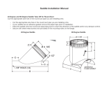
The Small ByPass Humidifier can be installed on either the supply or return plenum of a forced air handling system
Easy reversible installation right hand or left hand.
Read complete instructions before mounting the humidifier. The unit is 12%"W x 123/4"H x 91/8"D.The dimensions and serviceability must
be considered when selecting the best location for the unit.
If the furnace has central cooling, the humidifier bypass duct must have a damper. The damper should be closed during the cooling season.
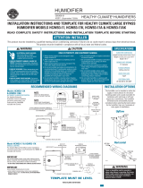
Diegrom A:
FOR OPERATION DURING "HEAT CALL" ONLY
120VAC
"HUM" AND "N"
TERMINALS
ON FURNACE
t20 VAC_'l _VAC
TRANSFORMER
24 VAC
SOLENOID VALVE
LEADS
HUMIDIFIER
Humidifier Control
©2003 International Comfort Products (USA)
Lewisburg, TN 37091
TEMPLATE MUST BE LEVEL
DP10005943
616 01 1005 00

i
READ REVERSE SiDE FIRST J
READ COMPLETE SAFETY
TOP
i READ REVERSE SIDE FIRST i
iNSTRUCTiONS AND iNSTALLATiON TEMPLATE BEFORE STARTING
TEMPLATE MUST BE LEVEL
1 Placeuniton flatsurfaceand pull
front cover upon rightside.It snaps
loose.Removeevaporativeassembly.
6 Reinstall the evaporative
assembly complete with the
evaporativemediaby fittingthedrain
tubeinto theroundreceptacleat the
bottomofthe unit.Pushtheassembly
in atthetopagainstthebeveledtabs.
Replacethe front cover and attach
nameplate with appropriate brand
name.
/
/
9 Connect tubing fromthe saddle
valve to the inlet side of the solenoid
valve using 1/4" O.D. copper tubing
(not furnished). DOUBLE WRENCH
TO PREVENTLEAKING!
2 The unitisassembledfor leftside
discharge. If right discharge is
necessary,removethe right and left
screws from the unit interior side
walls and exchangethe two sides.
Reassemblewithscrews.
7 DISCONNECT ELECTRICAL
POWER TO FURNACE BEFORE
PROCEEDING. The Humidifier
Controlis designed for low voltage
service to control humidification
equipment.An increase in relative
humidity expands the nylon ribbon
that opensthe controlswitchto stop
operation on the humidifier. A
decrease in relative humidity
reversestheprocess andclosesthe
controlswitch. Install the Humidifier
Control.
TO iNSTALL ON COPPER OR
PLASTICPiPE
a) Place rubbergasket in centerof
hole in top saddleclamp.Place
top and bottom saddle clamp
around water pipe. Using bolts,
tightensaddle clamps, evenly-
clampsshouldbe parallel- DO
NOTover-tighten.
b) Screwvalvebodyinto openingin
topsaddleclampandtighten.
c) Tighten gland nut onto valve
body.
d) Install1/4"watersupplylinefrom
humidifier using compression
fittings.
e) Youare now readyto piercethe
pipe.Turnhandle untilspindleis
firmlyseatedintovalvebody.The
water pipe is now fully pierced.
Turningspindleinshutsvalveoff.
Openvalvecompletelyfornormal
operation.
3 Usethistemplateformarkingthe
unitopeningtobecutinplenum.Draw
alevellineatleastthreeinchesabove
furnace jacket for clearance of the
drain line and solenoid valve.Tape
templateinpositionandtracearound
entire outside edges. Remove
template and accurately cut the
plenum opening accordingly,being
carefulto avoid injuryfrom sharp
edges,
LOCATION
1. LocateHumidifierControloninsidewall
of living area approximately5' above
floor,orin thefurnacereturnair plenum
or duct. For return air plenum
installation use Humidifier Control
Adapter Plate, Fast part # 4463
(Not Included/
2. Donotlocatecontrolin the directpathof
furnacedischargeairor draftsfromopen
doorsandwindows.
Do not install where operation might be
affected by lamps, sunlight, fireplace
registers, radiators, concealed air ducts
and pipes, or room occupants.
4. The basic rules for location of
thermostats also apply to Humidifier
Control
TOiNSTALLONSTEELORBRASS
PiPE
a) Shut off water supply.Open any
faucetto relievewaterpressure.
b) Drill3/16"diameterholeinto pipe
wheresaddlevalvewillbeplaced.
c) Place rubbergasket in centerof
holeintopsaddleclamp.
d) Placetopsaddleclampassembly
over hole so that lance fits into
hole.
e) Place top and bottom saddle
clamparoundwaterpipe.
f) Screwvalvebodyinto openingin
topsaddleclampandtighten.
g) Tighten gland nut onto valve
body.
h) Install1/4"watersupplylinefrom
humidifier using compression
fittings.
NOTE: For pipe over 1" O.D., use
1/4"-20,1-3/4"longbolts.
4 Place the unit into the plenum
opening so that the locking tabs on
the bottom are closed down onto the
lower sheet metal edge.While holding
the unit in place, install two screws at
the top of the unit interior. '
GENERALiNSTRUCTiONS
1. DO NOT ATTEMPTTO REPAIROR
RECALIBRATE CONTROL. Controls
requiringserviceshould bereturnedto
yourdistributor.
2. Control must be installed using 24 volts!
3. Make sure no bare wires are exposed or
insulation damaged. Insulation on wire
should extendto head of binding screws.
4.. Make sure all splices are mechanically
and electrically secure.
5. To remove dirt or other foreign matter
from nylon ribbon and control interior,
dust lightly with a fine, soft brush.
I_¸
/
/
1 0 Connect1/2"I.D.plastichose
(not furnished) from unit to floor
drain. Be sure drain hose has
continuousslope. Use caution with
hose clamp, be sure not to over
tighten andcrack drainspud. Note:
Do not sweat or directly attach
metal drain line to fitting. Do not
use solvent type adhesive when
connecting plastic drain hose,
since damage to fitting could
result.
5 Installa 6" collarina convenient
locationonthe oppositeplenum.Slip
on a 90° elbow and measure the
length of 6" round duct requiredto
maketheconnection.The6"ductwill
fit intotheroundcollaronthesideof
theunit. If thefurnacehascentralair
conditioning, add a duct damper.
Assemble components with sheet
metalscrews.Supportbypassducts
in excessof4' topreventsagging.
Tapinto a watersupplytinewith
thesaddlevalvefurnished.Thehumid-
ifierwilI functionwith cold,hot,soft-
enedor unsoftenedwater.Theuseof
servicehot water (140°FMAX.)and
constant blower operationwill pro-
videmaximumevaporativecapacities.
NOTE:Thesaddlevalveisdesigned
to befullyopenedor closed.Donot
useittoregulatewaterflow.
1 1 Opensaddlevalveandturn on
furnace.Turn up HumidifierControl
to operateunit.Allow unitto rununtil
water is observed coming out of
drain line. Check to see if unit is
water tight and all electrical
componentsfunctionproperly.Reset
HumidifierControlto recommended
level.
/