Page is loading ...


Revision History
Version: 1.0
April 2001
Industrial Devices Corporation (IDC) strives to maintain effective communication with all
users and potential users of our products. If you have any questions or concerns regarding
this technical manual or the product it covers, please contact:
Industrial Devices Corporation
3925 Cypress Drive
Petaluma, CA 94954
TEL: (800) 747-0064
FAX: (707) 789-0175
FROM OUTSIDE THE U.S. CALL (707) 789-1000
WEB SITE: www.idcmotion.com
EMAIL: info@idcmotion.com


Table of Contents
i
Table of Contents
CHAPTER 1 - IMPULSE OVERVIEW ...............................................................................................1-1
CHAPTER 2 - SHIPPING CONTENTS .............................................................................................2-1
CHAPTER 3 - CONNECTING AND INSTALLING YOUR IMPULSE ...............................................3-1
A. C
ONNECTING
A
M
OTOR
TO
THE
I
MPULSE
....................................................................................3-3
B. S
ERIAL
C
OMMUNICATION
C
ONNECTIONS
...................................................................................3-4
Making RS-232/RS-485 Connections ...................................................................................3-4
Daisy-Chaining Impulse Drives .............................................................................................3-5
Multi-Dropping with RS-485 ..................................................................................................3-5
Troubleshooting RS-232C Communication Problems ...........................................................3-6
C. C
ONNECTING
AN
IDC K
EYPAD
..................................................................................................3-7
Using a Keypad with Impulse RS232C .................................................................................3-7
Using a Keypad with Impulse RS485 ....................................................................................3-7
D. C
ONNECTING
AC P
OWER
.........................................................................................................3-8
E. LED DIAGNOSTIC
I
NDICATIONS
.................................................................................................3-8
F. CONNECTING
I
NPUTS
AND
O
UTPUTS
.........................................................................................3-9
G. M
OUNTING
THE
I
MPULSE
D
RIVE
..............................................................................................3-10
Environmental and Installation Requirements .....................................................................3-10
Mounting Arrangements ......................................................................................................3-10
Impulse Dimensions ............................................................................................................3-11
Inserting and Removing Mounting Brackets from the Impulse ............................................3-12
Impulse DIN-Rail Mounting .................................................................................................3-13
CHAPTER 4 - CONFIGURING IMPULSE WITH APPLICATION DEVELOPER™ ..........................4-1
I
NSTALLING
A
PPLICATION
D
EVELOPER
ON
W
INDOWS
95/98/2000/ME/NT .......................................4-1
U
SING
A
PPLICATION
D
EVELOPER
...................................................................................................4-2
F
INE
-T
UNING
Y
OUR
A
PPLICATION
.................................................................................................4-10
A
XIS
S
ETUP
.................................................................................................................................4-10
M
OTOR
.......................................................................................................................................4-11
M
ECHANICS
.................................................................................................................................4-12
C
OMMAND
...................................................................................................................................4-13
X-S
MOOTHNESS
(X
TREME
S
MOOTHING
™) ...................................................................................4-15
A
DVANCED
(A
DVANCED
T
UNING
) ..................................................................................................4-17
I/O S
ETUP
...................................................................................................................................4-18
I/O D
ESCRIPTIONS
.......................................................................................................................4-18
S
TORED
M
OVE
S
ETUP
- E
DITING
S
TORED
M
OVES
........................................................................4-21
F
ILE
M
ENU
..................................................................................................................................4-23
E
DIT
M
ENU
..................................................................................................................................4-23
S
ETUP
M
ENU
..............................................................................................................................4-23
C
OMMUNICATIONS
M
ENU
.............................................................................................................4-24
R
UN
M
ENU
..................................................................................................................................4-25
V
IEW
M
ENU
.................................................................................................................................4-26
U
PDATING
Y
OUR
I
MPULSE
O
PERATING
S
YSTEM
: ...........................................................................4-27
CHAPTER 5 - CONFIGURING IMPULSE WITH AN IDC KEYPAD .................................................5-1

Table of Contents
ii
S
ECTION
1 - I
NTRODUCTION
TO
THE
FP100 I
MPULSE
K
EYPAD
.........................................................5-1
S
ECTION
2 - C
ONFIGURING
I
MPULSE
WITH
AN
IDC K
EYPAD
...........................................................5-11
Configuring Impulse with the Keypad ..................................................................................5-12
Open a File ..........................................................................................................................5-12
Using the EDIT > SETUP Menus to Configure the Impulse ................................................5-12
MOTOR SETUP ..................................................................................................................5-12
COMMAND SETUP ............................................................................................................5-13
MECHANICAL SETUP ........................................................................................................5-15
MOTOR TUNING SETUP (X-Smoothness) ........................................................................5-16
ADVANCED SETUP ...........................................................................................................5-17
I/O SETUP ..........................................................................................................................5-20
Move Menus - Using Stored Moves ....................................................................................5-22
UNIT# ..................................................................................................................................5-24
CHAPTER 6 - HARDWARE REFERENCE .......................................................................................6-1
I
MPULSE
S
PECIFICATIONS
..............................................................................................................6-1
R
EMOTE
M
OUNTING
Y
OUR
K
EYPAD
................................................................................................6-2
E
XTENDING
THE
C
ABLE
L
ENGTH
TO
Y
OUR
K
EYPAD
.........................................................................6-2
K
EYPAD
M
OUNTING
T
EMPLATE
.......................................................................................................6-3
I
MPULSE
I/O S
CHEMATICS
..............................................................................................................6-4
O
PTIONAL
A
CCESSORIES
FOR
Y
OUR
I
MPULSE
.................................................................................6-7
I
MPULSE
-A
PPLICABLE
IDC M
OTORS
...............................................................................................6-9
CHAPTER 7 - TROUBLESHOOTING THE IMPULSE ......................................................................7-1
T
ROUBLESHOOTING
T
ABLE
.............................................................................................................7-1
L
IMITS
T
ABLES
..............................................................................................................................7-3
CHAPTER 8 - PRODUCT SUPPORT............................................................................................... 8-2
W
ARRANTY
& R
EPAIRS
..................................................................................................................8-3
APPENDIX A: RECOMMENDED WIRING PRACTICES FOR IDC CONTROLS ............................A-1
APPENDIX B - IMPULSE ADVANCED PROGRAMMING ..............................................................B-1
APPENDIX C - USING NON-IDC MOTORS WITH THE IMPULSE .................................................C-1
C
USTOM
OR
U
SER
-D
EFINED
M
OTORS
...........................................................................................C-2
INDEX........................................................................................................................END OF MANUAL

Chapter 1 - Impulse Overview
1-1
Chapter 1 - Impulse Overview
The Impulse is the latest microstepping drive from Industrial Devices Corporation and this
innovative drive will move your applications with a combination of features previously unheard of
in the motion control industry.
The Impulse is a self-contained microstepping drive designed to operate permanent-magnet linear
and rotary hybrid step-motors. Its internal control hardware is based on a digital signal processor
(DSP) operating a pair of IGBT power amplifiers. The Impulse is fully protected against short-
circuits and overheating.
Responding to users who demand the ultimate in value and reliability, the Impulse employs the
following features and performance enhancements:
This manual will enable you to 1) quickly setup and verify that your Impulse is operational, 2)
configure and program the Impulse for your specific application, and 3) successfully troubleshoot
possible performance problems.
Feature Function
Open Loop Stall Detect
TM
Allows a motor to run without an encoder and still be able to detect a stall
Dynamic Smoothing
TM
Move profiles are smoothed to minimize jerk
Multi-Stepping
TM
For full-stepping with the smoothness of microstepping
Motion Node
7 simple moves can be stored in the Impulse and activated via inputs or
serial port. This feature is optional.
Xtreme Smoothing
TM
6 component “gain” settings for low-speed smoothness, reduced vibration,
and more usable torque
IDeal Performance Probe Automatic fine-tuning of the Impulse for optimum performance with the con-
figured motor
I/O Capabilities 4 configurable inputs and one configurable output provide the user with
flexibility
Configurable I/O Polarity I/O polarity can be set to Active High or Active Low ensuring compatibility
with a wide range of controls
Diagnostic LED Green for power ON/ENABLED, flashing green for DISABLED, red for ON/
UNCONFIGURED, flashing red for FAULTS
Ultra-Compact Packaging Top-notch performance, while consuming a minimal amount of space
Resolution Up to 100,000 steps/rev
FLASH Firmware Downloadable software facilitates quick upgrades over the internet
Current Reduction Modes Enable Stop (current reduced to 75% of drive setting if no motion occurs
during a user-programmed amount of time)
Enable Idle (user-defined current reduction percentage if no motion occurs
during a user-programmed amount of time)
Anti-Resonance Provides optimum torque and nulls mid-range instability
Integrated Cooling Tunnel For maximum performance and multiple drive mounting capability
Regenerative Circuit Dumps excessive power during deceleration

Chapter 1 - Overview
1-2
This page intentionally left blank

Chapter 2 - Shipping Contents
2-1
Chapter 2 - Shipping Contents
Your Impulse will arrive equipped as listed in section #1. If any parts or accessories are missing, please call
IDC Customer Support at: (800) 747-0064. Sections 2 and 3 are provided as reference material.
1
- What You Will Receive if You Ordered the Following:
2
- Ordering and Identifying an Impulse
3
- Accessories Currently Available for the Impulse
Impulse + FP100
(or FP220) Keypad
Impulse Only
Impulse + FP100-RS485
(or FP220-RS485) Keypad
1. Impulse Microstepping Drive 1. Impulse Microstepping Drive 1. Impulse Microstepping Drive
2. AC power cord for Impulse 2. Motor Connector 2. AC power cord for Impulse
3. Motor Connector 3. AC power cord for Impulse 3. Motor Connector
4. FP100 (or FP220) Keypad 4. IDCMotion Software 4. FP100 (or FP220) -RS485 Keypad
5. Remote cable for Keypad 5. Impulse Quick Setup/Ref. Guide 5. Keypad Power Supply
6. Keypad mounting gasket 6. Impulse User’s Manual 6. Remote cable for Keypad
7. Keypad mounting template 7. Keypad mounting gasket
8. IDCMotion Software 8. Keypad mounting template
9. Impulse Quick Setup/Ref. Guide 9. IDCMotion Software
10.
Impulse User’s Manua
l
10. Impulse Quick Setup/Ref. Guide
11.
Impulse User’s Manua
l
IMPULSE Input Power Capability Drive Type Communication Accessories
IM L T4
Using the tables below, fill in the boxes and you will be able to order or identify your Impulse:
Input Power Drive Type Accessories (order separately)
L Line Voltage 120 VAC T4 Stepper Drive, 4 A *FP_ _ _-_ _ Keypad Configuration
DB25BO 25 pin D-Shell Breakout Board
Capability Communication SS-IO 25 pin I/O Cable - 2 ft.
M Motion Node Version 2 RS232 SS-IO-6 25 pin I/O Cable - 6 ft.
D Drive Version 4 RS485 SS-RS232 Serial Comm. Cable
PCS-5004 Keypad to PC Cable
PCS-5110 Screw-Mounting Bracket
PCS-5111 DIN Rail Mounting Bracket
*FP100, FP220, FP100-RS485, or FP220-RS485
DB25BO
Screw Terminal
Breakout Board
SS-IO (2ft. cable)
SS-IO-6 (6ft. cable)
SS-RS232
Impulse to
PC Cable
PCS-5004
Keypad to PC
Cable
PCS-5110
Screw-Mount
Bracket
PCS-5111
DIN Rail
Mounting
Bracket

Chapter 2 - Shipping Contents
2-2
This page intentionally left blank

Chapter 3 - Connecting and Installing Your Impulse
3-1
Chapter 3 - Connecting and Installing Your Impulse
The purpose of this chapter is to provide information that will help you connect and install your
Impulse drive in its intended application.
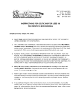
The Impulse drive easily interfaces with a PC, PLC, Step & Direction Motion Controller, or IDC
keypad. Block diagrams of several Impulse-based applications are shown below.
Typical Impulse Applications
PC
or
Keypad
Indexer
Impulse
961/962
RS232C
RS485
Digital Inputs (4)
Digital Output (1)
Fault Output
Step/Dir/Shutdown
or
Single or
Multi-Axis
PC
or
PLC
I/O TX RX
Unit #1
Unit #99
RS232C
1 - 7 Stored Moves
PC
or
PLC
RS485
Unit #1
Unit #32
I/O

Chapter 3 - Connecting and Installing Your Impulse
3-2
Read This Page Before Your Begin!
CAUTION!
•
Always
use caution
when working with mechanical systems. Gears and screw-
driven cylinders are capable of exerting tremendous force against an obstruc-
tion.
•
Always ensure that power to your system is OFF
before performing any
maintenance activity, or making any connections or adjustments.
•
Do not insert objects into the Impulse drive
. High voltages could cause per-
sonal injury, and equipment could be damaged beyond repair.
•
Do not open the Impulse drive.
The factory warranty will be voided if the drive
is opened.

Chapter 3 - Connecting and Installing Your Impulse
3-3
A. Connecting a Motor to the Impulse
Connecting an IDC Motor
The A+, A-, B+, and B- phase outputs power the motor windings.
Connect motor wires to the motor connector (supplied) and plug the wired connector into the drive.
Drawings below provide color codes for IDC motors.
GND is internally connected to the earth pin on the power connector. This provides a convenient
terminal for grounding the motor frame and a motor cable shield. Note: If the motor is mounted on
a machine that is grounded, do not connect the motor to GND.
The two INTLK pins must be jumpered together on the motor connector to allow power to the
motor.
CAUTION! Do not remove the motor connector from the Impulse drive while power is
applied. Removing the connector while power is applied could damage the connector pins.
Do not extend the interlock jumper wire to provide protection for another connector interface. The
interlock circuit is susceptible to trips caused by noise-pickup in cables (20 kHz switching).
Note: This is a high-impedance safety-interlock circuit. If the interlock wire breaks, or the connector
is removed, the current to the motor is immediately stopped, the drive faults (latches) and the LED
on the front panel of the Impulse will flash five times (see LED Diagnostics on p. 3-8).
Connecting a Non-IDC Motor
One of the Impulse drive’s more advanced features, Open Loop Stall Detect
TM
, is guaranteed only
when matched with one of IDC’s S or P-series motors.
IDC’s S and P series motors have custom windings to provide optimum dynamic performance with
the Impulse. If you use another manufacturer’s motor, refer to Non-IDC Motors in Chapter 6,
Hardware Reference, for more information.
IDC Motor Wiring/Color Codes
Quick Disconnect Cable Wire Color
A+ Red
A- Red/Yellow
*GND Green
B+ Red/White
B- Red/Black
*Gray-colored Quick Disc. cables are
shielded - connect shield to GND.
P31/32/33S12/21/23/32/33 P21/22, S21/23
YELLOW
WHT/RED
RED
WHT/YEL
SHIELD
BLACK
WHT/ORG
ORANGE
WHT/BLK
YELLOW
WHT/RED
RED
WHT/YEL
BLACK
WHT/ORG
ORANGE
WHT/BLK
GREEN/YEL
YELLOW
WHT/YEL
WHT/RED
RED
SHIELD
BLACK
WHT/BLK
WHT/ORG
ORANGE
Series Parallel Parallel
Motor
Connector

Chapter 3 - Connecting and Installing Your Impulse
3-4
B. Serial Communication Connections
Making RS-232/RS-485 Connections
The standard Impulse drive uses a 3-wire implementation of RS-232C. The RX, TX, and COM lines
are the serial signals supported. No hardware handshaking is required. Note that some RS-232C
devices require handshaking, such as RTS and CTS. It is the responsibility of the user to disable this
handshaking via software or hardware (see Troubleshooting RS-232C Communication Problems on
page 3-6 for more information).
If you will be using RS-485 communication, the typical 5-wire interface connection to a “host” is
shown below. See “Multi-Dropping Impulse Drives with RS-485” on the next page for information
on using termination resistors. Note: the maximum cable length for RS-485 communication is 4,000
feet.
Make your RS-232C connection as shown below. The PC Cable (IDC P/N SS-RS232) shown below,
is an ideal choice for making trouble-free RS-232C connections to the Impulse.
Comm Port Settings
RS-232C/RS-485
Baud Rate 19200 (fixed)
Stop Bits 1
Data Bits 8
Parity None
XON/XOFF Yes
IDC P/N
SS-RS232
RS-485
TX-
TX+
RX-
RX+
COM
COM PORT
9-Pin
Connector
3 (TX)
2 (RX)
5 (COM)
COM PORT
RS-232C
RS-485 Host

Chapter 3 - Connecting and Installing Your Impulse
3-5
Daisy-Chaining Impulse Drives
Your Impulse also supports daisy chaining. The unit address (range 1-99) can be set via the keypad
or in Application Developer.
Rules for Daisy Chain Operation
1. Units on a daisy chain must be “device addressed’ (numbered) in order for communications to
work properly. A unit’s address should increment upward as you move down the daisy chain
from the PC (see illustration below).
2. Do not duplicate unit addresses.
3. Any loose RS-232C connections or miswiring along the daisy chain will cause communications
to fail. Please double check wiring if communication problems arise.
4. Please call IDC if you need to daisy chain more than 99 drives.
5. The hardware diagram below shows how to connect the daisy chain.
Multi-Dropping with RS-485
If you will be “multi-dropping” Impulse drives with RS485, add 120-ohm termination resistors
across RX and TX connections of the last unit as shown below:
RX TX COM
RX TX COM
RX TX COM
RX
TX
COM
.
.
Impulse
Unit 1
Unit 2
Unit 3
PC/Host
RS-232C
Device
Impulse
Impulse
RS-485
Host
Add resistors as
shown here:

Chapter 3 - Connecting and Installing Your Impulse
3-6
Troubleshooting RS-232C Communication Problems
If communications between computer and Impulse are unsuccessful, one or more of the following
procedures will usually solve the problem:
1. Host transmit (TX) must be connected to receive (RX) of the drive unit, and receive (RX) of the
host must be connected to transmit (TX) of the drive. If communication fails, try switching
connections on either the host or the drive.
2. Some serial ports may require handshaking.
Jumper RTS to CTS, and DSR to DTR (see table).
3. Check your ground connections. The COM
terminal should be isolated from earth ground. Use
DC common or signal ground as your reference - do not use earth ground or shield.
4. Voltage between TX and COM should be -8.0 to -12.0 VDC. Voltage between RX and COM
should be 0 to -0.5 VDC. Consult factory if measured voltages are outside these ranges.
5. For RS-232C only: If any cable is more than 50 ft. long, you should use a line driver, optical
coupler, or shield. Shields must be connected to earth ground at one end only.
6. Reminder for PDA Users: Programs such as Palm’s Hotsync Manager take over a comm. port.
Be sure to close/exit these types of programs if you are using serial communication with your
Impulse.
7. Important Application Note Regarding PC Com Port: PC FIFO (First In First Out) Buffers
should be used and adjusted to the highest settings for fastest performance. This applies to both
Receive and Transmit Buffers.
• In your Windows operating system, go to Start > Settings > Control Panel > System >
Device Manager > Ports (Com 1, Com 2) > Port Settings > Advanced > Buffer.
• Select Use FIFO Buffers, and ensure both Buffers (Receive and Transmit) are adjusted to
the High setting for best performance.
Jumpers 9 pin D 25 pin D
RTS to CTS 7 to 8 4 to 5
DSR to DTR 4 to 6 6 to 20

Chapter 3 - Connecting and Installing Your Impulse
3-7
C. Connecting an IDC Keypad
Two versions of IDC keypads can be used with the
Impulse drive. The FP100 works only with the
Impulse, while the FP220 can be used with the Impulse
as well as IDC’s Smart Drives (see keypad-specific
information below).
The COM PORT on the front panel of the Impulse is
used for connecting either version of keypad.
Power is applied to either version of keypad when
power is connected to the Impulse.
Using a Keypad with Impulse RS232C
FP100 Keypad
Connect the FP100 Keypad to the Impulse with the
cable supplied with the keypad.
FP220 Keypad (Version 3.0 or higher)
Only FP220 Keypad versions 3.0 and higher will work
with the Impulse drive.
To use an FP220 keypad with your Impulse, you must
set DIP-switch #3 to the ON position and switch #s 1,
2, and 4 to OFF.
The FP220 uses the same keypad cable as the FP100.
Using a Keypad with Impulse RS485
Impulse RS485 requires either the FP100-RS485 or
FP220-RS485 keypad.
On the FP220-RS485 keypad only, set DIP switches as
described above. Both FP100-RS485 and FP220-
RS485 keypad are connected as follows:
1. Connect the keypad cable to the keypad and to the
Impulse.
2. Connect the keypad power supply cable to the
keypad as shown in the illustration.
3. Plug in the AC adapter.
1
2
3
COM
PORT
I/O
COM
PORT
Keypad
Keypad
Keypad with Impulse RS232C
Keypad with Impulse RS485

Chapter 3 - Connecting and Installing Your Impulse
3-8
D. Connecting AC Power
There is no ON/OFF switch on the Impulse. AC power is
applied by plugging the *power cord (included) into the
connector on top of the Impulse.
Input voltage must be in the range of 120 VAC ± 10%, single
phase, 50/60 Hz, 500 VA max @ 4 Amps. Operation outside
these specifications will result in reduced performance, drive
faults, and may damage the drive.
When power is applied, the LED on front of the drive should
briefly turn red, then steady green. If a red light is present, see
Section E of this chapter for more information on fault detection
codes.
*Note: If the AC power cord requires replacement, the
replacement must be rated for Hard Usage or Extra Hard
Usage.
E. LED Diagnostic Indications
The Impulse drive detects and resolves fault conditions (see table below). Faults are signaled by
either a steady red or a flashing red LED on the front panel. A solid green LED indicates normal
operation. A slowly flashing green LED indicates a shutdown (disabled), while a rapidly flashing
green LED signals a regen dump. Faults are cleared by either 1) cycling power, 2) sending a RESET
command via the serial port or configurable logic input, or 3) probing the motor if the LED is steady
red.
For more detailed explanation of faults refer to Chapter 7, Troubleshooting the Impulse.
To AC
Power
Supply
Diagnostic LED Indications
LED Signal Indication
Green (steady) Normal Operation
Slow Flashing Green Shutdown
Quick Flashing Green Regen Dump
Red (steady) Motor Not Probed
1 Flash Red Stalled
2 Flashes Red Undervoltage Fault
3 Flashes Red Overvoltage Fault
4 Flashes Red Overcurrent Fault
5 Flashes Red Interlock Fault
6 Flashes Red Overtemperature Fault
7 Flashes Red EEPROM Checksum Fault
LED

Chapter 3 - Connecting and Installing Your Impulse
3-9
F. Connecting Inputs and Outputs
Connect your inputs and outputs to IDC’s 961/962 Indexer according to the information below.
Schematics for Impulse I/O circuits can be found in Chapter 6, Hardware Reference
Application Notes
1. On 961/2, ensure that Step/Direction and Differential Jumpers are installed (see 961/2 manual).
2. If using IDC P/N SS-I/O or SS-I/O-6 cable, cut one end of the cable if necessary (see table
below for SS-I/O cable color-code). If making your own cable, or using a non-IDC indexer,
refer to the Impulse I/O Schematics (Chap. 6) and the 25-pin Connector drawing below.
3. Use a shielded cable, and connect the shield only at the Impulse. Connect shield to pin 9.
4. IDC offers a 25-pin screw-terminal breakout board (shown below) to add convenience and
flexibility to your application. Terminals on the breakout board match the pins of the 25-pin
connector on the Impulse.
5. When wiring TTL signals to other manufacturer’s indexers, the Step TTL command signals
from the controller should be wired to Step +, the Direction signal to Dir +, and the Shutdown
signal to SD + (Step -, Dir -, and SD - should not be connected). Remember, the drive common
must be connected to the controller common.
6. Activating the Shutdown input disables the drive amplifier and de-energizes the motor. When
this input is OFF the drive is enabled and the motor is energized. The polarity of this input is
configurable.
7. The open-collector Fault Output turns ON (Active High) when any one of the LED-indicated
conditions occur (see Section E, LED Diagnostic Indicators). The output stays ON while the
LED flashes.
IDC Indexer
(962 Dual-Axis Shown)
Breakout
Board
P/N DB25BO
T
O
D
R
I
V
E
1
SHLD
FLT-
FLT+
SD-
SD+
DIR-
DIR+
STEP-
STEP+
SHLD
COM
+5
Z-
Z+
B-
B+
A-
A+
1
2
3
4
5
6
7
8
COM
COM
1
2
3
4
5
6
7
8
O
U
T
P
U
T
S
I
N
P
U
T
S
IDC Cable P/N: SS-IO/SS-IO-6
Pin Impulse Signal Wire Color Pin Impulse Signal Wire Color Pin Impulse Signal Wire Color
1 STEP + Brown 10 COM Gray 19 COM Black/White
2 STEP - Red 11 COM White 20 Reserved Red/Black
3 DIR + Orange 12 Reserved Black 21 Reserved Orange/Black
4 DIR - Pink 13 Reserved Brown/White 22 COM Yellow/Black
5 SD + Yellow 14 INPUT 1 Red/White 23 Output 1 Green/Black
6 SD - Green 15 INPUT 2 Orange/White 24 Reserved Gray/Black
7 FAULT + Light Green 16 INPUT 3 Green/White 25 Reserved Pink/Black
8 FAULT - Blue 17 INPUT 4 Blue/White
Note: Cable SHIELD is internally connected to the
DB25 metal housing.9 Drain Violet 18 COM Violet/White

Chapter 3 - Connecting and Installing Your Impulse
3-10
G. Mounting the Impulse Drive
This section includes installation requirements, Impulse dimensions, installing and removing
mounting brackets, and mounting the Impulse on a DIN rail.
Environmental and Installation Requirements
• Operating Ambient Temperature: Max. 50º C (122º F) @ 4 Amps
• Storage Temperature: Max. 65º C (149º F)
• Not intended for use in humidity above 95% (non-condensing), or at altitudes greater than
3,048 meters [10,000 ft.]
• Heat Dissipation @ 4 A (typical): 32 Watts
• Leave 6 inches above and below drives for airflow and wiring.
• Leave 0.1 inch between drives for easier mounting.
• Air supplied to the Impulse must be uncontaminated.
Mounting Arrangements
The illustration on the right shows an example
of an acceptable mounting arrangement.
COM
PORT
I/O
COM
PORT
I/O
COM
PORT
I/O
COM
PORT
I/O
COM
PORT
I/O
COM
PORT
I/O
COM
PORT
I/O
COM
PORT
I/O
COM
PORT
I/O
COM
PORT
I/O
6.0 in.
/