


USER MANUAL
INSULATION RESISTANCE METER
MIC-10 ● MIC-30
SONEL S.A.
Wokulskiego 11
58-100 Świdnica
Poland
Version 2.03 20.11.2023

MIC-10 ● MIC-30 – USER MANUAL
2
MIC-10 / MIC-30 meter is a modern, easy and safe measuring device. Please acquaint yourself with
the present manual in order to avoid measuring errors and prevent possible problems related to
operation of the meter.

MIC-10 ● MIC-30 – USER MANUAL
3
CONTENTS
1 Safety ................................................................................................................ 4
2 Meter configuration ......................................................................................... 5
3 Measurements .................................................................................................. 6
3.1 Measurement of insulation resistance ...................................................................... 6
3.1.1 Double-lead measurement (with a shielded lead) .............................................................. 6
3.1.2 Three-lead measurement (with a shielded lead) .............................................................. 10
3.1.3 Measurements with WS-04 adapter ................................................................ 10
3.2 Low-voltage measurement of resistance ................................................................ 12
3.2.1 Measurement of resistance of protective conductors and equipotential bonding with
200 mA current ............................................................................................................... 12
3.2.2 Measurement of resistance ............................................................................................. 14
3.2.3 Compensation of test leads resistance ............................................................................ 15
3.3 Voltage measurement ............................................................................................ 16
3.4 Remembering the last measurement result............................................................ 16
4 Memory of measurement result data ............................................. 17
4.1 Storing the measurement results in the memory .................................................... 17
4.2 Viewing memory data ............................................................................................. 19
4.3 Deleting memory data ............................................................................................ 20
4.3.1 Deleting bank data .......................................................................................................... 20
4.3.2 Deleting the whole memory ............................................................................................. 21
5 Data transmission ............................................................................ 22
5.1 Computer connection accessories ......................................................................... 22
5.2 Data transmission with Bluetooth module .............................................................. 23
5.3 Data transmission with OR-1 radio module ............................................................ 24
6 Firmware update .............................................................................. 25
7 Power supply of the meter ............................................................................ 26
7.1 Monitoring of the power supply voltage .................................................................. 26
7.2 Replacing battery/rechargeable batteries ............................................................... 26
7.3 General principles regarding using NiMH rechargeable batteries .......................... 27
8 Cleaning and maintenance ........................................................................... 27
9 Storage ............................................................................................................ 28
10 Dismantling and disposal ............................................................................. 28
11 Technical specifications ............................................................................... 28
11.1 Basic data .............................................................................................................. 28
11.2 Other technical data ............................................................................................... 31
11.3 Additional data ....................................................................................................... 32
11.3.1 Additional uncertainties according to IEC 61557-2 (RISO) ................................................. 32
11.3.2 Additional uncertainties according to IEC 61557-4 (RCONT 200mA) .................................. 32
12 Manufacturer .................................................................................................. 32

MIC-10 ● MIC-30 – USER MANUAL
4
The icon with the meter name is placed next to sections of the text that refer to specific
features of the device. All other parts of the text relate to all types of the instrument.
1 Safety
MIC-10 / MIC-30 meter is designed for performing check tests of protection against electric shock in mains
systems. The meter is used for making measurements and providing results to determine safety of electrical
installations. Therefore, in order to provide conditions for correct operation and the correctness of the obtained
results, the following recommendations must be observed:
Before you proceed to operate the meter, acquaint yourself thoroughly with the present manual and
observe the safety regulations and specifications determined by the producer.
Any application that differs from those specified in the present manual may result in a damage to the device
and constitute a source of danger for the user.
MIC-10 / MIC-30 meters must be operated only by appropriately qualified personnel with relevant
certificates authorising the personnel to perform works on electric systems. Operating the meter by
unauthorised personnel may result in damage to the device and constitute a source of danger for the user.
During measurements of insulation resistance, dangerous voltage up to 1 kV occurs at the ends of test
leads of the meter.
Before the measurement of insulation resistance you must be sure that tested object is disconnected from
the power supply
During the measurement of insulation resistance do not disconnect test leads from the tested object before
the measurement is completed (see par. 3.1.1); otherwise the capacitance of the object will not be
discharged, creating the risk of electric shock,
Using this manual does not exclude the need to comply with occupational health and safety regulations
and with other relevant fire regulations required during the performance of a particular type of work. Before
starting the work with the device in special environments, e.g. potentially fire-risk/explosive environment,
it is necessary to consult it with the person responsible for health and safety.
It is unacceptable to operate the following:
A damaged meter which is completely or partially out of order,
A meter with damaged test leads insulation,
A meter stored for an excessive period of time in disadvantageous conditions (e.g. excessive
humidity). If the meter has been transferred from a cool to a warm environment with a high level of
relative humidity, do not start measurements until the meter is warmed up to the ambient temperature
(approximately 30 minutes).
Displayed BATT symbol indicates insufficient voltage of power supply and the need to charge the
accumulator or replace batteries.
Symbols ErrX, where X is a number 1…9, indicate incorrect operation of the meter. If after restarting the
device this situation is repeated - it indicates that the meter is damaged.
Before measurement, choose a correct measurement function and make sure that test leads are
connected to respective measuring terminals.
Do not operate a meter with an open or incorrectly closed battery (accumulator) compartment or power it
from other sources than those specified in the present manual.
Meter inputs are electronically protected against overloads (caused by e.g. connecting the meter to a live
circuit) up to 550V, for voltmeter up to 600V.
Repairs may be carried out only by an authorised service point.
Note:
An attempt to install drivers in 64-bit Windows 8 and Windows 10 may result in displaying
"Installation failed" message.
Cause: Windows 8 and Windows 10 by default blocks drivers without a digital signature.
Solution: Disable the driver signature enforcement in Windows.
Note:
Due to continuous development of the meter’s software, the actual appearance of the display, in case
of some of the functions, may slightly differ from the display presented in this operating manual.

MIC-10 ● MIC-30 – USER MANUAL
5
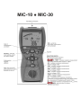
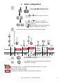
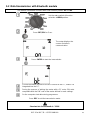
2 Meter configuration
Turn on the meter by pressing and
keeping SET/SEL button pressed.
Use and buttons to go to the next
parameter.
Use and buttons to change the
parameter value. The value or symbol to be
changed is flashing.
The symbol indicates an active parameter,
the - symbol indicates an inactive one.
Set the parameters according to the following algorithm:
Parameter
Auto-
OFF
Change PIN
Absorption
coefficients
Pairs of
WS-04
adapter
Beep
signalling
pressed
push-button
Selection
of
power
supply
source
Software
update
Symbol(s)
,
or
Press ENTER to validate the last change and go to
the measurement function,
or
Press ESC to go the measurement function without
validating the changes.
Notes:
- Each change DAR PI <-> Ab1Ab2 will set standard times t1, t2 and t3:
- for PI and DAR t1=30s, t2=60s, t3=none,
- for Ab1 and Ab2 t1=15s, t2=60s, t3=none.
- Description of a firmware update is presented in chapter 6.

MIC-10 ● MIC-30 – USER MANUAL
6
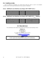
3 Measurements
3.1 Measurement of insulation resistance
WARNING:
Measured object must not be live.
Note:
During measurement, especially of high resistances, make sure that test leads
do not touch each other and the probe (crocodile clips), because such a contact
may cause the flow of surface currents resulting in additional error in
measurement results.
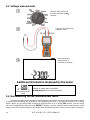
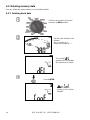
3.1.1 Double-lead measurement (with a shielded lead)
Set the rotary switch of function
selection at one of RISO
positions, selecting
simultaneously measuring
voltage ( for position
50...1000V - selected with 10V
step). The meter is in the
voltage measurement mode.
Press SET/SEL push-button to select
time used for calculating the absorption
coefficients - t1, t2, t3.
For the position of the selector 50...1000V, an
additional option is available to select the
measuring voltage UN.
Use and the meter enters
into the setting of UN, t1, t2, t3.
Use and buttons to change
the parameter value.
Press ENTER to confirm settings
(confirmed by beep) or press ESC to leave
without saving the changes.

MIC-10 ● MIC-30 – USER MANUAL
7
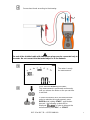
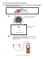
Connect test leads according to the drawing.
The end of the shielded cable with two banana plugs may be connected only to
the meter. Do not connect it to the tested object or to the network.
The meter is ready
for measurement.
Press and hold START push-button.
The measurement is performed continuously
until you release the button or the pre-set time
is reached.
In order to maintain (lock) the measurement
order to maintain the measurement, press
ENTER while holding START - push-button
pressed - the following symbol will be
displayed . In order to interrupt the
measurement, press ESC or START.

MIC-10 ● MIC-30 – USER MANUAL
8
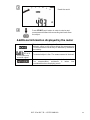
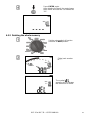
View of the screen
during
measurement.
Using SET/SEL you may
display the leakage current IL instead of
UISO.
After measuring is
completed, read the
result.
Use and to see:
the capacitance of the tested object,
individual components of the result in the
following order:
(RISO + UISO)→(C + IL)→(Rt1 + It1)→(Rt2 + It2)→
(Rt3 + It3)→(Ab1(DAR) + UISO)→(Ab2(PI) + UISO)→
(RISO + UISO), where C – is the capacitance of the
tested object.
Notes:
During measurements of insulation resistance, dangerous voltage up to 1 kV
occurs at the ends of test leads of MIC-10 / MIC-30 meter.
It is forbidden to disconnect test leads before the measurement is completed.
Failure to obey the above instruction will lead to high voltage electric shock and
make it impossible to discharge the object tested.

MIC-10 ● MIC-30 – USER MANUAL
9
- Disabling t2 will also disable t3.
- Timer measuring the measurement time is started when UISO voltage is stabilized.
- Symbol LIMIT I! indicates working with current limiting (e.g. when charging an object).
- If the work with limited current lasts for 20 seconds, the measurement is interrupted.
- When the timer passes specific points (tx times) a long beep is emitted.
- If any of the measured values of partial resistance is out of range, the value of the absorption
coefficient is not displayed – the display shows dashes.
- During the measurement LED is lit in orange.
- After completion of measurement, the capacitance of the object tested is discharged by shorting test
terminals with the resistance of 100k.
- Capacitance of the object is measured at the end of the measurement during the object discharge.
- If during the measurement, an external voltage is present, after 20 seconds the measurement is
stopped, is displayed and two-tone beep is emitted, LED will lit in red.
Additional information displayed by the meter
Test voltage is present on terminals of the meter.
You must consult the manual.
The meter is ready for measurement.
This inscription displayed after the measurement indicates
noise in the system during the measurement. The
measurement result may be affected by additional
uncertainty.
Activation of current limit. The symbol displayed is
accompanied by a continuous audio signal.
Leakage current too high (breakdown of insulation during
the measurement.)
Discharging of the object tested after the measurement.
LED is lit
in red, two-tone
acoustic signal
The tested object is live. The measurement is blocked.
Discharged batteries (rechargeable batteries).

MIC-10 ● MIC-30 – USER MANUAL
10
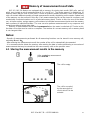
3.1.2 Three-lead measurement (with a shielded lead)
In order to eliminate the influence of surface currents in the devices of up to 1kV, a three-lead
measurement is used. For example, to measure the inter-winding resistance of a small motor, connect
G socket of the meter with the motor housing:
3.1.3 Measurements with WS-04 adapter
NOTE
Measurements with WS-04 are possible at the measurement voltage of 500V, for
higher voltages the measurement is blocked.
WS-04 provides automatic measurement of up to 3 combinations of test leads from N, L and PE.
The adapter is ended at one side with a plug to be connected to the input terminals of the meter, while
at the other side with a standard outlet plug with a grounding plug. Combinations of leads that are to be
automatically tested, are defined in the meter settings, see Chapter 2.
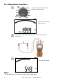
Set the rotary switch of function
selection at one of RISO positions,
selecting simultaneously measuring
voltage (position 50...1000V -
selected with 10V step). The meter
is in the voltage measurement
mode.
After inserting WS-04
into the socket, the
screen displays a
message indicating
the detection of the
adapter.

MIC-10 ● MIC-30 – USER MANUAL
11
Set the measuring voltage UN (applies only for 50...1000V
position of the switch), and times t1, t2, t3 as in double-lead
measurement. These settings relate to the measurement of
insulation resistance for each pair of leads selected in the main
settings.
Connect WS-04 plug to the socket tested.
Start the measurement as in case of double-lead measurement.
The meter measures
the insulation
resistance for selected
pairs of leads in the
following order: L-N, L-
PE, N-PE.
After measuring is
completed, read the
result.
Use and to view the individual components
of the measurement as in double-lead measurement
and for pairs L-N, L-PE, N-PE.
Note:
- In cases of errors , LIMIT I! the measurement is interrupted only for the current pair of leads and
not for the entire measurement.
- In case of error the entire measurement is interrupted.
- Other comments and displayed symbols as for the double-lead measurement.

MIC-10 ● MIC-30 – USER MANUAL
12
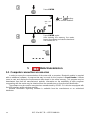
3.2 Low-voltage measurement of resistance
3.2.1 Measurement of resistance of protective conductors and equipotential
bonding with 200 mA current
NOTE
The meter measures RCONT:
unidirectionally,
bidirectionally (±200mA).
Set the rotary switch of function
selection at RCONT position.
The meter is ready for
measurement.
Connect the meter to the object tested.
The measurement starts automatically when the meter detects a
resistance within the measurement range.
The measurement may be also triggered manually by pressing
START push-button.

MIC-10 ● MIC-30 – USER MANUAL
13
Read the result.
Press START push-button in order to start a next
measurement without disconnecting test leads from
the object.
Additional information displayed by the meter
This inscription displayed after the measurement
indicates noise in the system during the measurement
The measurement result may be affected by additional
uncertainty.
LED is lit
in red, two-tone
acoustic signal
The tested object is live. The measurement is blocked.
Resistance compensation completed for test leads
The compensation resistance is taken into
consideration when displaying result.

MIC-10 ● MIC-30 – USER MANUAL
14
3.2.2 Measurement of resistance
Set the rotary switch of function
selection at RX position.
The meter is ready for
measurement.
Connect the meter to the object tested. The measurement is
continuous.
Read out the result.
Note:
- For R <30Ω there is a continuous beep and LED lights green.

MIC-10 ● MIC-30 – USER MANUAL
15
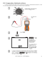
3.2.3 Compensation of test leads resistance
In order to eliminate the impact of the resistance of test leads on measurement result (RCONT and
RX), the compensation (auto-zeroing) of resistance may be performed.
Set the rotary switch of function
selection at RZERO position.
Short the test
leads.
Press START.
and
are displayed,
confirming the
completion of test
leads resistance
compensation.
The compensation is
available for RCONT
and RX and is active
even after the meter
is switched off and
on again.
In order to remove the compensation made (and return to default
calibration), perform the above-mentioned activities with test leads
open – messages and disappear, the following
message is displayed .

MIC-10 ● MIC-30 – USER MANUAL
16
3.3 Voltage measurement
Set the rotary switch of
function selection at U
position.
Connect the meter to a
voltage source.
Measurement is
performed in a
continuous manner.
Additional information displayed by the meter
LED is lit in red,
two-tone acoustic
signal
Voltage is higher than acceptable.
Immediately disconnect the test leads.
3.4 Remembering the last measurement result
Result of the latest measurement is remembered by the meter until a next measurement is started
or measurement settings are changed or the measuring function is changed by means of the rotary
switch. When you go to the initial screen of a given function (e.g. by using ESC button), you can recall
this result automatically after pressing ENTER. Similarly, you can view the latest measurement result
after turning off and then turning on the meter (if the position of function selector has not been changed).

MIC-10 ● MIC-30 – USER MANUAL
17
4 Memory of measurement result data
MIC-10 / MIC-30 Meters are equipped with a memory for storing test results (990 cells, each of
which may contain a set of measurements of RISO and RCONT). The whole memory is divided into 10
memory banks with 99 cells in each bank. Thanks to dynamic memory allocation, each of the memory
cells can contain different quantity of single measurement results, depending on the needs. Optimal use
of the memory can be ensured in this way. Each measurement result can be stored in a memory cell
marked with a selected number and in a selected memory bank. Thanks to this, the user of the meter
can, at his/her option, assign memory cell numbers to individual measurement points and the memory
bank numbers to individual facilities. The user can also perform measurements in any sequence and
repeat them without losing other data.
Memory of measurement result data is preserved when the meter is switched off. Thanks to this,
the data can be later read or sent to a computer. The number of a current memory cell or memory bank
is not changed either.
Notes:
- Results of measurements performed for all measuring functions can be stored in one memory cell,
excluding RX and U .
- After entering the measurement result, the number of the cell is automatically incremented.
- It is recommended to delete the memory after reading the data or before performing a new series of
measurements that may be stored into the same memory cells as the previous ones.
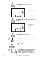
4.1 Storing the measurement results in the memory
After completing measurement
press ENTER.
The cell is empty.
The cell is occupied
by the same type of
result, which is to be
entered.

MIC-10 ● MIC-30 – USER MANUAL
18
Use and to preview the results.
The cell is occupied
by a different type of
result, than the one
which is to be
entered.
Use and to preview the results stored in the
memory cell.
The cell is fully
occupied.
Use and to view the results.
Use SET/SEL to select active cells or banks which
may be changed.
Use and to change the number of a cell or
bank.
Press ENTER, to save the result in the memory
or ESC to display the result without saving it.
Saving is indicated by a triple beep and by a
rectangle displayed on the main display field.
Page is loading ...
Page is loading ...
Page is loading ...
Page is loading ...
Page is loading ...
Page is loading ...
Page is loading ...
Page is loading ...
Page is loading ...
Page is loading ...
Page is loading ...
Page is loading ...
Page is loading ...
Page is loading ...
Page is loading ...
Page is loading ...
-
 1
1
-
 2
2
-
 3
3
-
 4
4
-
 5
5
-
 6
6
-
 7
7
-
 8
8
-
 9
9
-
 10
10
-
 11
11
-
 12
12
-
 13
13
-
 14
14
-
 15
15
-
 16
16
-
 17
17
-
 18
18
-
 19
19
-
 20
20
-
 21
21
-
 22
22
-
 23
23
-
 24
24
-
 25
25
-
 26
26
-
 27
27
-
 28
28
-
 29
29
-
 30
30
-
 31
31
-
 32
32
-
 33
33
-
 34
34
-
 35
35
-
 36
36


Ask a question and I''ll find the answer in the document
Finding information in a document is now easier with AI
Related papers
Other documents
-
Gossen MetraWatt METRISO PRIME 10 Operating instructions
-
-
 METREL EurotestPV Lite User manual
-
-
-
Gossen MetraWatt PROFITEST PRIME Operating instructions
-
 METREL MI 3152 User manual
-
 METREL MI 3152 User manual
-
-
Gossen MetraWatt METRISO INTRO Operating instructions


