Landoll 7500 VT Plus Adjustable User manual
- Type
- User manual


Manuals for the 7530 VT Plus
MANUAL NUMBER MANUAL NAME
F-941 7530 VT Plus Operator’s Manual
F-942 7530 VT Plus Parts Manual

i
Table of Contents
1 Introduction
Introduction .............................................................. 1-1
Understanding Safety Statements ............................................. 1-2
Decal Safety ............................................................. 1-2
Transporting Safety ........................................................ 1-2
Attaching, Detaching, and Storage ............................................ 1-3
Maintenance Safety ........................................................ 1-3
High Pressure Fluid Safety .................................................. 1-3
Protective Equipment ...................................................... 1-3
Chemical Safety .......................................................... 1-3
Prepare for Emergencies ................................................... 1-3
Tire Safety ............................................................... 1-3
Safety Chain ............................................................. 1-4
2 Standard Specifications
Introduction .............................................................. 2-1
Owner Assistance ......................................................... 2-1
Warranty Registration ...................................................... 2-1
Warranty Statement ....................................................... 2-2
Model Specifications ....................................................... 2-5
General Torque Specifications (rev. 4/97) ....................................... 2-6
Hydraulic Fitting Torque Specifications ......................................... 2-7
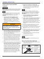
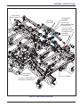
3 Assembly Instructions
7530 VT Plus Frame and Hitch Assembly ....................................... 3-2
Spare Tire Assembly (Optional) .............................................. 3-2
Leveler Assembly ......................................................... 3-5
Wing Frame and Fold Assembly .............................................. 3-7
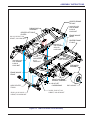
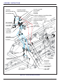
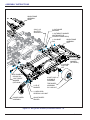
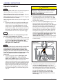
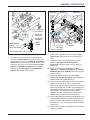
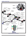
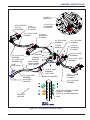
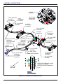
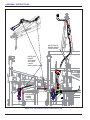
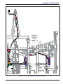
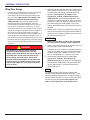
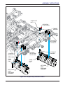
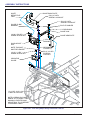
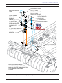
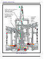
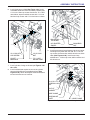
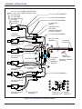
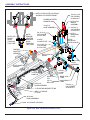
Hydraulic Installation ...................................................... 3-10
Center Disc Gangs ....................................................... 3-26
Wing Disc Gangs ......................................................... 3-28
LED Light Installation ..................................................... 3-46
Conditioner Reel Spring Installation (Option) ................................... 3-50
Hydraulic Conditioner Reel Installation (Option) ................................. 3-54
Rear Tow Hitch Installation ................................................. 3-62
Final Assembly .......................................................... 3-65

ii F-941-0522
4 Operation and Maintenance
Tractor Preparation ........................................................4-2
VT Plus Preparation ........................................................4-2
Attaching to the Tractor .....................................................4-2
Hydraulic Lift System .......................................................4-3
Hydraulic Fold System ......................................................4-4
General Operation .........................................................4-5
Field Operation ...........................................................4-5
Leveling (Side to Side) ......................................................4-6
Leveling (Front-to-Rear) ....................................................4-8
Hydraulic Leveler Adjustment ................................................4-8
Hitch Adjustment .........................................................4-10
Scraper Adjustment .......................................................4-11
Disc Blades .............................................................4-12
Disc Gang Assembly ......................................................4-12
Front Gauge Wheels ......................................................4-13
Depth Stop Adjustment (Manual) .............................................4-13
Hydraulic Maintenance ....................................................4-14
Transport ...............................................................4-14
Rear Hitch Jack Operation ..................................................4-16
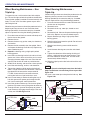
Wheel Bearing Maintenance – Non Triple-Lip ...................................4-18
Wheel Bearing Maintenance -- Triple-Lip ......................................4-18
Lubrication Maintenance ...................................................4-19
Lift Cylinder Maintenance ..................................................4-19
Storage ................................................................4-21
Conditioner Reels ........................................................4-22
Hydraulic Conditioner Reels ................................................4-22
5 Troubleshooting Guide

1-1
Chapter 1
Introduction
Introduction
The Landoll Model 7530 VT is a quality product designed to give years of trouble free performance. By following each
section of this manual, your system will perform as designed for you and your operation.
CHAPTER 1 Gives basic instructions on the use of this manual and understanding the safety
statements.
CHAPTER 2 Gives product specifications for the equipment. These specifications supply lengths and
measures for your equipment. A Standard Bolt Torque Table is provided to give
guidelines for bolt torques to be used when servicing this product.
CHAPTER 3 Contains assembly instructions for your 7530 VT. When these procedures are correctly
followed, your equipment should provide you years of trouble-free operation and service.
CHAPTER 4 Instructs how to operate your equipment before using it, and describes adjustments
needed. Gives practical advice for the care and maintenance of your Landoll equipment.
Drawings in this section locate adjustment points on the equipment.
IF YOU HAVE ANY QUESTIONS CONTACT:
LANDOLL COMPANY, LLC
1900 NORTH STREET
MARYSVILLE, KANSAS 66508
PHONE # (785) 562-5381 or (800) 428-5655
OR
FAX # (888) 527-3909
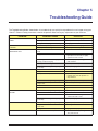
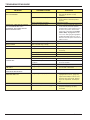
CHAPTER 5 Is a troubleshooting guide to aid in diagnosing and solving problems with the 7530 VT.
PARTS MANUAL Is a separate manual showing the various assemblies, sub-assemblies, and systems.
Refer to that manual when ordering Landoll replacement parts. Order parts from your
Landoll dealer.
WARRANTY The Warranty Registration form is included with the product documents. Fill it out and
mail it within 15 days of purchase.
NOTE: IMPROPER ASSEMBLY, MODIFICATION, OR MAINTENANCE OF YOUR
LANDOLL MACHINE CAN VOID YOUR WARRANTY.
COMMENTS Address comments or questions regarding this publication to:
LANDOLL COMPANY, LLC
1900 NORTH STREET
MARYSVILLE, KANSAS 66508
ATTENTION: PUBLICATIONS - DEPT. 55

1-2 F-941-0522
INTRODUCTION
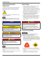
Understanding Safety
Statements
You will find various types of safety information on the
following pages and on the machine signs (decals)
attached to the vehicle. This section explains their
meaning.
The Safety Alert Symbol means ATTENTION! YOUR
SAFETY IS INVOLVED!
NOTE
Means that failure to follow these instructions could
cause damage to the equipment or cause it to operate
improperly.
NOTICE
CAUTION
WARNING
DANGER
NOTE
Make sure you read and understand the information
contained in this manual and on the machine signs
(decals) before you attempt to operate or maintain this
vehicle.
The safety statements contained in this manual relate to
the operation of the Model 7530 VT.
Decal Safety
1. Examine safety decals and be sure you have the
correct safety decals for the implement.
2. Keep these signs clean so they can be observed
readily. It is important to keep these decals cleaned
more frequently than the implement. Wash with soap
and water or a cleaning solution as required.
3. Replace decals that become damaged or lost. Also,
be sure that any new implement components
installed during repair include decals which are
assigned to them by the manufacturer.
4. When applying decals to the implement, be sure to
clean the surface to remove any dirt or residue.
Where possible, sign placement should protect the
sign from abrasion, damage, or obstruction from
mud, dirt, oil etc.
DANGER
Transporting Safety
IMPORTANT
It is the responsibility of the owner/operator to
comply with all state and local laws.
1. When transporting the implement on a road or
highway, use adequate warning symbols, reflectors,
lights and slow moving vehicle sign as required. Slow
moving tractors and towed implements can create a
hazard when driven on public roads. They are difficult
to see, especially at night.
2. Do not tow an implement that, when fully loaded,
weighs more than 1.5 times the weight of the towing
vehicle.
3. Carry reflectors or flags to mark the tractor and
implement in case of breakdown on the road.
Special notice - read and thoroughly understand
Caution means serious equipment or other
property damage can occur if instructions on this
label are not properly followed.
Warning means serious injury or death can occur
if safety measures or instructions on this label
are not properly followed.
Danger means a life-threatening situation exists.
Death can occur if safety measures or
instructions on this label are not properly
followed.
• Do not allow anyone to ride on the tractor or
implement. Riders could be struck by foreign
objects or thrown from the implement.
• Never allow children to operate equipment.
• Keep bystanders away from implement during
operation.

INTRODUCTION
1-3
4. Do not transport at speeds over 20 MPH under good
conditions. Never travel at a speed which does not
allow adequate control of steering and stopping.
Reduce speed if towed load is not equipped with
brakes.
5. Avoid sudden stops or turns because the weight of
the implement may cause the operator to lose control
of the tractor. Use a tractor heavier than the
implement.
6. Use caution when towing behind articulated steering
tractors; fast or sharp turns may cause the implement
to shift sideways.
7. Keep clear of overhead power lines and other
obstructions when transporting. Know the transport
height and width of your implement.
Attaching, Detaching, and
Storage
1. Do not stand between the tractor and implement
when attaching or detaching implement unless both
are not moving.
2. Block implement so it will not roll when unhitched
from the tractor.
3. Store in an area where children normally do not play.
Maintenance Safety
1. Understand the procedure before doing the work.
Use proper tools and equipment.
2. Make sure all moving parts have stopped.
3. Do not make adjustments or lubricate implement
while it is in motion.
4. Block the implement so it will not roll when working
on or under it to prevent injury.
High Pressure Fluid Safety
1. Escaping fluid under pressure can be nearly invisible
and have enough force to penetrate the skin causing
serious injury. Use a piece of cardboard, rather than
hands, to search for suspected leaks.
2. Any fluid injected into the skin must be surgically
removed within a few hours or gangrene may result.
3. Avoid the hazard by relieving pressure before
disconnecting hydraulic lines.
Protective Equipment
1. Wear protective clothing and equipment.
2. Wear clothing and equipment appropriate for the job.
Avoid loose fitting clothing.
3. Because prolonged exposure to loud noise can
cause hearing impairment or hearing loss, wear
suitable hearing protection, such as earmuffs or
earplugs.
Chemical Safety
1. Agricultural chemicals can be dangerous. Improper
use can seriously injure persons, animals, plants, soil
and property.
2. Read chemical manufacturer's instructions and store
or dispose of unused chemicals as specified.
3. Handle chemicals with care and avoid inhaling
smoke from any type of chemical fire.
4. Store or dispose of unused chemicals as specified by
the chemical manufacturer.
Prepare for Emergencies
1. Keep a First Aid Kit and Fire Extinguisher handy.
2. Keep emergency numbers for doctor, ambulance,
hospital and fire department near the phone.
Tire Safety
1. Tire changing can be dangerous and should be
performed by trained personnel using correct tools
and equipment.
2. When inflating tires, use a clip-on chuck and
extension hose long enough to allow you to stand to
one side, not in front of or over the tire assembly. Use
a safety cage if available.
3. When removing and installing wheels use
wheel-handling equipment adequate for the weight
involved.

1-4 F-941-0522
INTRODUCTION
Safety Chain
1. Use a chain with a strength rating equal to or greater
than the gross weight of towed machinery, which is
10,100 pounds minimum in accordance with ASAE
S338.2 specifications. If two or more implements are
pulled in tandem, a larger chain may be required.
Chain capacity must be greater then the TOTAL
weight of all towed implements.
2. A second chain should be used between each
implement.
3. Attach the chain to the tractor draw-bar support or
specified anchor location. Allow only enough slack in
the chain to permit turning. The distance from hitch
pin to attachment point or intermediate support point
should not exceed 9 inches.
4. Replace the chain if any links or end fittings are
broken, stretched or damaged.
5. Do not use a safety chain for towing.

2-1
Chapter 2
Standard Specifications
Introduction
This manual is compiled as a guide for owners and
operators of the 7530 adjustable vt plus. Read it carefully
so as to be able to follow the suggestions made. Please
take time to understand the proper maintenance
schedule and SAFE operation of your equipment.
In the event that a new and inexperienced operator is
placed in charge of running the equipment, they should
read and understand, that part of the manual for proper
maintenance and SAFE operation, and to be trained in
regard by an experienced operator.
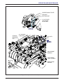
Owner Assistance
If customer service or repairs are needed, contact your
Icon dealer. They have trained personnel, parts and
service equipment specially designed for Icon products.
Your machine’s parts should only be replaced with Icon
parts. Have the Serial Number and complete Model
Number available when ordering parts from your Icon
dealer See Figure 2-1.
Figure 2-1: ID Plate
Warranty Registration
Be certain to register the adjustable vt plus Online
registration at www.landoll.com within 10 days of
purchase or lease, in order to be on file at Landoll and
eligible for Warranty.
Take time to read and understand the Warranty for this
product, See Figure 2-2. and See Figure 2-3.
Landoll reserves the right to make changes and/or add
improvements to it’s products at any time without
obligation to previously manufactured equipment.
Please take time to complete the following information for
your personal reference, should you need to contact your
Dealer with questions or parts needs.
MODEL_____________________________________
SERIAL #____________________________________
DATE OF PURCHASE__________________________
DEALER NAME________________________________
We at Landoll wish to thank you for purchasing our
product. We have spent considerable time and effort to
research, design, test and develop this machine and are
confident it will serve you in the use for which it was
designed.
MODEL #
SERIAL #
MADE IN USA 1-573-010006
Landoll Company, LLC
Marysville, Kansas
www.landoll.com

2-2 F-941-0522
STANDARD SPECIFICATIONS
Warranty Statement
Figure 2-2: Landoll Tillage Warranty (1 of 2)
LANDOLL TILLAGE PRODUCT THREE YEAR LIMITED WARRANTY
Landoll Company, LLC warrants each new serial numbered Whole Good Tillage product, when properly
assembled, adjusted, serviced, and normally operated, to be free from defects in materials and workmanship for
a period of three (3) years, unless otherwise noted, from the date of delivery. Date of delivery shall be the date
the Dealer places the product in the possession of the original retail purchaser, and must be confirmed by the
Dealer submitting a properly completed Landoll Company, LLC Warranty Registration Form to the Landoll
Company, LLC Warranty Department. Warranty starts the day the product is rented or leased. This limited
warranty shall be transferable until the expiration date.
Landoll Company, LLC shall repair, or at its option, replace any part(s) of the product determined, by Landoll
Company, LLC, to be defective. Landoll Company, LLC may request the return of part(s), freight prepaid via a
carrier approved by the Landoll Warranty Staff, to Landoll Company, LLC for further evaluation. If the part is
determined to be defective, Landoll Company, LLC will refund the freight charges incurred in returning the
defective part(s), and will prepay replacement part(s) freight charges.
This limited warranty requires pre-authorization by the Landoll Company, LLC Warranty Staff of any warranty
related utilization of components or labor, and is subject to specific exclusions and does not apply to any product
which has been: 1) subjected to or operated in a manner which, at any time, have exceeded the product design
limits: 2) repaired or altered outside our factory in any way so as, in the judgment of Landoll Company, LLC , to
affect its stability or reliability: 3) subject to misuse, negligence, accident, or has been operated in a manner
expressly prohibited in the instructions; or not operated in accordance with practices approved by Landoll
Company, LLC . Operating the product in soils containing rocks, stumps or obstructions may void the warranty
in its entirety. Excessive acres, consistent with nonseasonal very large farming operations, and, non-agricultural
activities, may further limit the terms of this warranty.
The sole obligation of Landoll Company, LLC under this warranty shall be limited to repairing or replacing, at its
option, part(s) which shall be identified to Landoll Company, LLC by way of a pre-authorized Landoll Company,
LLC e-mail Warranty Claim Form Warranty, expressed or implied, will be denied on any product not properly
registered with the Landoll Company, LLC Warranty Department within ten (10) days of the first retail sale.
As stated above, Landoll Company, LLC Warranty Staff will identify components listed on a Warranty Claim
required to be returned for further analysis. All parts returned to Landoll Company, LLC must be shipped with a
Return Materials Authorization (RMA) provided by the Landoll Company, LLC Warranty Staff. Defective
components must returned by the purchaser to Landoll Company, LLC with transportation and freight charges
prepaid within fifteen (15) days after receipt of the RMA. The examination conducted by Landoll Company, LLC
of returned parts shall disclose to its satisfaction the extent the component may be detective. All parts and labor
warranty MUST be pre-authorized by Landoll Company, LLC Warranty Staff. Failure to do so may result in no
warranty payment of any kind. Labor will be reimbursed in accordance with published shop rates pre-approved
by the Landoll Company, LLC Warranty Staff. Time authorized for specific work will be limited, where appropriate,
to the hours listed in the Landoll Company, LLC authorized Labor Rate Guide.
®

STANDARD SPECIFICATIONS
2-3
Figure 2-3: Landoll Tillage Warranty (2 of 2)
LANDOLL TILLAGE PRODUCT THREE YEAR LIMITED WARRANTY (Continued)
USER'S OBLIGATION:
1. Read the Operator's Manual
2. Understand the safe and correct operating procedures pertaining to the operation of the product.
3. Lubricate and maintain the product according to the maintenance schedule in the Operator's Manual.
4. Inspect machine and have parts repaired or replaced when continued use of the produce would cause
damage or excessive wear to other parts.
5. Contact the Landoll Company, LLC Dealer for repair or replacement of defective parts. Mileage incurred
by the Landoll Company, LLC Dealer is the customer's responsibility.
This 3-Year Limited Warranty SHALL NOT APPLY TO:
(See Warranty Procedure Manual for details.)
1. Ground Engaging Tools
2. Vendor Warranty Only Parts
WARRANTY LABOR:
1. Considered during the first year of warranty only.
2. During the second and third year:
• Warranty labor is not covered. Customer is responsible for removing, replacing and returning the
defective part(s) to the Landoll Dealer
THIS WARRANTY IS EXPRESSIVELY IN LIEU OF ALL OTHER WARRANTIES OF MATERIAL,
WORKMANSHIP, DESIGN, APPLICATION OR OTHERWISE WITH RESPECT TO ANY EQUIPMENT,
WHETHER EXPRESS, IMPLIED OR STATUTORY, INCLUDING WARRANTIES OF MERCHANTABILITY
AND FITNESS FOR A PARTICULAR PURPOSE, AND LANDO LL COMP ANY, LLC SHALL NOT BE
LIABLE FOR SPECIAL OR CONSEQUENTIAL DAMAGES OF ANY KIND ON ACCOUNT OF ANY
LANDOLL PRODUCT.
NO EMPLOYEE OR REPRESENTATIVE IS AUTHORIZED TO CHANGE THIS WARRANTY, VERBALLY
OR IN WRITING, OR GRANT ANY OTHER WARRANTY. LANDOLL COMPANY, LLC, WHOSE POLICY IS
ONE OF CONTINUOUS IMPROVEMENT, RESERVES THE RIGHT TO MAKE CHANGES WITHOUT
OBLIGATION TO MODIFY PREVIOUSLY PRODUCED EQUIPMENT.
This warranty does not expand, enlarge upon or alter in any way, the warranties provided by the original
manufacturers and suppliers of component parts and accessories. This warranty excludes such parts or
accessories which are not defective, but may wear out and have to be replaced during the warranty period,
including, but not limited to, light bulbs, paint, and the like. (Tire Warranties are expressly excluded from
Landoll Company, LLC warranty herein.) Purchaser is expected to pay all repairs or replacement costs, in
connection with this Agreement, including sales and other taxes immediately upon completion of work performed.
LIMITATION OF LIABILITY: Landoll Company, LLC shall not be liable to purchaser for any incidental or
consequential damages suffered by the purchaser, including, but not limited to, any commercially reasonable
charges, expenses or commissions incurred in connection with effecting cover or any other reasonable
expense incident to the delay or other breach of warranty by Landoll Company, LLC, loss of anticipated profits,
transportation expenses due to repairs, non-operation or increased expense of operation costs of purchased
or replaced equipment, claim of customers, cost of money, any loss of use of capital or revenue, equipment rental,
service trips, or for any special damage or loss of any nature arising at any time or from any cause whatsoever.
LIMITATION OF REMEDY: In the event of Landoll Company, LLC failure to repair the product subject to the
warranty contained herein, the purchaser's sole and exclusive remedy against Landoll Company, LLC shall be
for the repair or replacement of any defective part or parts of the product subject to work or repair within the
time period and manner set forth herein.
This exclusive remedy shall not be deemed to have failed of its essential purpose so long as Landoll Company,
LLC is willing and able to repair or replace defective parts in the prescribed manner.

2-4 F-941-0522
STANDARD SPECIFICATIONS

STANDARD SPECIFICATIONS
2-5
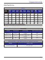
Model Specifications
7530 VT
Model
Number
Rear
Gang cut
at 10 °
Transport
Width
Transport
Height
Blade
Diameter
No. of
Blades
No. of
Bearings
Spindle
Size
Wheel
Bolt
Pattern
Estimated
Weight
7530-23 23’- 1”’ 14’ - 7” 12’ - 6” 24” 78 10/10 3” 8 Bolt 23,750lbs.
7530-26 26’- 6”’ 14’ - 7” 13’ - 6” 24” 90 10/10 3” 8 Bolt 26,840lbs.
7530-29 28’- 10” 14’ - 7” 14’ - 1” 24” 98 12/10 3” 8 Bolt 27,900lbs.
7530-32 32’- 4” 17’ - 11” 14’ - 1” 24” 110 14/12 3” 8 Bolt 30,940lbs.
7530-35 34’ - 8” 17’ - 11” 15’ - 1” 24” 118 14/14 3” 8 Bolt 31,500 lbs.
NOTE: Specifications Are Subject To Change Without Prior
Notification-Transport Height Can Vary With Reel Placement
Tire Inflation
Tire Size Tire Manufacturer Ply/Load Rating Inflation Pressure (Psi) (Max.)
480/45R17 AG BKT VF LOAD INDEX 167A8B/8000 LBS.
@ 25MPH 78 psi
380/55R X16.5 IMP Good Year LOAD INDEX 150AB/8/7400 LBS.
@ 30MPH 74 psi
410/50R X 16.5 IMP BKT LOAD INDEX 153A8/B/8,050 LBS.
@ 30MPH 73psi
Recommended Torque Specification For Lug Bolts and Nuts
Bolt Size Torque (FT. LBS.)
5/8-18 (Heavy Duty Disc) 100 - 125 FT. LBS.

2-6 F-941-0522
STANDARD SPECIFICATIONS
General Torque Specifications
(rev. 4/97)
Table 2-1: General Torque Specifications
TORQUE SPECIFIED IN FOOT POUNDS - This chart provides tightening torques for general purpose applications
when special torques are not specified on process or drawing. Assembly torques apply to plated nuts and cap-screws
assembled without supplemental lubrication (as received condition). They do not apply if special graphite moly-disulfide or
other extreme pressure lubricants are used. When fasteners are dry (solvent cleaned) add 33% to as received condition
torque. Bolt head identification marks indicate grade and may vary from manufacturer to manufacturer. Thick nuts must be
used on grade 8 cap-screws. Use value in [ ] if using prevailing torque nuts.
UNC
SIZE
SAE
Grade 2
SAE
Grade 5
SAE
Grade 8
UNF
SIZE
SAE
Grade 2
SAE
Grade 5
SAE
Grade 8
1/4-20 4 [5] 6 [7] 9 [11] 1/4-28 5 [6] 7 [9] 10 [12]
5/16-18 8 [10] 13 [13] 18 [22] 5/16-24 9 [11] 14 [17] 20 [25]
3/8-16 15 [19] 23 [29] 35 [42] 3/8-24 17 [21] 25 [31] 35 [44]
7/16-14 24 [30] 35 [43] 55 [62] 7/16-20 27 [34] 40 [50] 60 [75]
1/2-13 35 [43] 55 [62] 80 [100] 1/2-20 40 [50] 65 [81] 90 [112]
9/16-12 55 [62] 80 [100] 110 [137] 9/16-18 60 [75] 90 [112] 130 [162]
5/8-11 75 [94] 110 [137] 170 [212] 5/8-18 85 [106] 130 [162] 180 [225]
3/4-10 130 [162] 200 [250] 280 [350] 3/4-16 150 [188] 220 [275] 320 [400]
7/8-9 125 [156] 320 [400] 460 [575] 7/8-14 140 [175] 360 [450] 500 [625]
1-8 190 [237] 408 [506] 680 [850] 1-14 210 [263] 540 [675] 760 [950]
1-1/8-7 270 [337] 600 [750] 960 [1200] 1-1/8-12 300 [375] 660 [825] 1080 [1350]
1-1/4-7 380 [475] 840 [1050 1426 [1782] 1-1/4-12 420 [525] 920 [1150] 1500 [1875]
1-3/8-6 490 [612] 1010 [1375] 1780 [2225] 1-3/8-12 560 [700] 1260 [1575] 2010 [2512]
1-1/2-6 650 [812] 1460 [1825] 2360 [2950] 1-1/2-12 730 [912] 1640 [2050] 2660 [3325]
1-3/4-5 736 [920] 1651 [2063] 2678 [3347] 1-3/4-12 920 [1150] 2063 [2579] 3347 [4183]
METRIC:
Coarse thread metric class 10.9 fasteners and class 10.0 nuts and through hardened flat washers, phosphate coated,
Rockwell “C” 38-45. Use value in [ ] if using prevailing torque nuts.
Nominal
thread
diameter
(mm)
Newton
Meters
(Standard
Torque)
Foot Pounds
(Standard
Torque)
Nominal
Thread
Diameter
(mm)
Newton
Meters
(Standard
Torque)
Foot Pounds
(Standard
Torque
6 10 [14] 7 [10] 20 385 [450] 290 [335]
7 16 [22] 12 [16] 24 670 [775] 500 [625]
8 23 [32] 17 [24] 27 980 [1105] 730 [825]
10 46 [60] 34 [47] 30 1330 [1470] 990 [1090]
12 80 [125] 60 [75] 33 1790 [1950] 1340 [1450]
14 125 [155] 90 [115] 36 2325 [2515] 1730 [1870]
16 200 [240] 150 [180] 39 3010 [3210] 2240 [2380]
18 275 [330] 205 [245] --------------- --------------- ---------------

STANDARD SPECIFICATIONS
2-7
Hydraulic Fitting Torque
Specifications
Table 2-2: Hydraulic Fitting Torque Specifications
TORQUE IS SPECIFIED IN FOOT POUNDS- 37oJIC, ORS, & ORB (REV. 10/97)
This chart provides tightening torques for general purpose applications when special torques are not specified on process or
drawing. Assembly torques apply to plated nuts and capscrews assembled without supplemental lubrication (as received
condition). They do not apply if special graphite moly-disulfide or other extreme pressure lubricants are used. When fasteners are
dry (solvent cleaned) add 33% to as received condition torque. Bolt head identification marks indicate grade and may vary from
manufacturer to manufacturer. Thick nuts must be used on grade 8 capscrews. Use value in [ ] if using prevailing torque nuts.
Parker Brand Fittings
Dash Size 37 Degree JIC O-Ring (ORS) O-Ring Boss (ORB)
-4 11-13 15-17 13-15
-5 14-16 --------------- 21-23
-6 20-22 34-36 25-29
-8 43-47 58-62 40-44
-10 55-65 100-110 58-62
-12 80-90 134-146 75-85
-16 115-125 202-218 109-121
-20 160-180 248-272 213-237
-24 185-215 303-327 238-262
-32 250-290 -------------- 310-340
Gates Brand Fittings
Dash Size 37 Degree JIC O-Ring (ORS) O-Ring Boss (ORB)
-4 10-11 10-12 14-16
-5 13-15 --------------- ---------------
-6 17-19 18-20 24-26
-8 34-38 32-40 37-44
-10 50-56 46-56 50-60
-12 70-78 65-80 75-83
-14 -------------- 65-80 --------------
-16 94-104 92-105 111-125
-20 124-138 125-140 133-152
-24 156-173 150-180 156-184
-32 219-243 -------------- --------------
Aeroquip Brand Fittings
Dash Size 37 Degree JIC O-Ring (ORS) O-Ring Boss (ORB)
-4 11-12 10-12 14-16
-5 15-16 --------------- 16-20
-6 18-20 18-20 24-26
-8 38-42 32-35 50-60
-10 57-62 46-50 75-80
-12 79-87 65-70 125-135
-14 -------------- -------------- 160-180
-16 108-113 92-100 200-220
-20 127-133 125-140 210-280
-24 158-167 150-165 270-360
-32 245-258 -------------- --------------

2-8 F-941-0522
STANDARD SPECIFICATIONS
Table provided for general use.
NOTES:

STANDARD SPECIFICATIONS
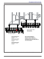
2-9
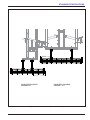
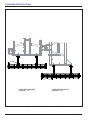
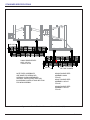
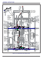
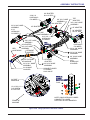
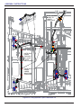
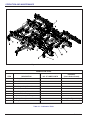
Figure 2-4: Conditioner Reel Placement 23’ (LH)
´
&21'5((/*$1*%$5
$66(0%/<´
´
&21'5((/*$1*%$5
$66(0%/<´

2-10 F-941-0522
STANDARD SPECIFICATIONS
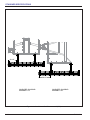
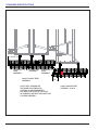
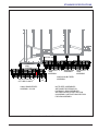
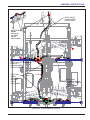
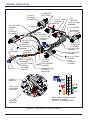
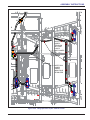
Figure 2-5: Conditioner Reel Placement 23’ (RH)
&21'5((/*$1*%$5
$66(0%/<´
&21'5((/*$1*%$5
$66(0%/<´
´
´

STANDARD SPECIFICATIONS
2-11
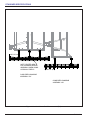
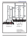
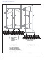
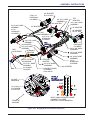
Figure 2-6: Conditioner Reel Placement 26’ (LH)
´
&21'5((/*$1*%$5
$66(0%/<´
´
&21'5((/*$1*%$5
$66(0%/<´

2-12 F-941-0522
STANDARD SPECIFICATIONS
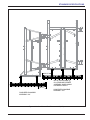
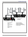
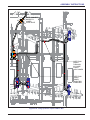
Figure 2-7: Conditioner Reel Placement 26’ (RH)
´
&21'5((/*$1*%$5
$66(0%/<´
´
&21'5((/*$1*%$5
$66(0%/<´
Page is loading ...
Page is loading ...
Page is loading ...
Page is loading ...
Page is loading ...
Page is loading ...
Page is loading ...
Page is loading ...
Page is loading ...
Page is loading ...
Page is loading ...
Page is loading ...
Page is loading ...
Page is loading ...
Page is loading ...
Page is loading ...
Page is loading ...
Page is loading ...
Page is loading ...
Page is loading ...
Page is loading ...
Page is loading ...
Page is loading ...
Page is loading ...
Page is loading ...
Page is loading ...
Page is loading ...
Page is loading ...
Page is loading ...
Page is loading ...
Page is loading ...
Page is loading ...
Page is loading ...
Page is loading ...
Page is loading ...
Page is loading ...
Page is loading ...
Page is loading ...
Page is loading ...
Page is loading ...
Page is loading ...
Page is loading ...
Page is loading ...
Page is loading ...
Page is loading ...
Page is loading ...
Page is loading ...
Page is loading ...
Page is loading ...
Page is loading ...
Page is loading ...
Page is loading ...
Page is loading ...
Page is loading ...
Page is loading ...
Page is loading ...
Page is loading ...
Page is loading ...
Page is loading ...
Page is loading ...
Page is loading ...
Page is loading ...
Page is loading ...
Page is loading ...
Page is loading ...
Page is loading ...
Page is loading ...
Page is loading ...
Page is loading ...
Page is loading ...
Page is loading ...
Page is loading ...
Page is loading ...
Page is loading ...
Page is loading ...
Page is loading ...
Page is loading ...
Page is loading ...
Page is loading ...
Page is loading ...
Page is loading ...
Page is loading ...
Page is loading ...
Page is loading ...
Page is loading ...
Page is loading ...
Page is loading ...
Page is loading ...
Page is loading ...
Page is loading ...
Page is loading ...
Page is loading ...
Page is loading ...
Page is loading ...
Page is loading ...
Page is loading ...
Page is loading ...
Page is loading ...
Page is loading ...
Page is loading ...
Page is loading ...
Page is loading ...
Page is loading ...
Page is loading ...
Page is loading ...
Page is loading ...
Page is loading ...
Page is loading ...
Page is loading ...
Page is loading ...
Page is loading ...
Page is loading ...
-
 1
1
-
 2
2
-
 3
3
-
 4
4
-
 5
5
-
 6
6
-
 7
7
-
 8
8
-
 9
9
-
 10
10
-
 11
11
-
 12
12
-
 13
13
-
 14
14
-
 15
15
-
 16
16
-
 17
17
-
 18
18
-
 19
19
-
 20
20
-
 21
21
-
 22
22
-
 23
23
-
 24
24
-
 25
25
-
 26
26
-
 27
27
-
 28
28
-
 29
29
-
 30
30
-
 31
31
-
 32
32
-
 33
33
-
 34
34
-
 35
35
-
 36
36
-
 37
37
-
 38
38
-
 39
39
-
 40
40
-
 41
41
-
 42
42
-
 43
43
-
 44
44
-
 45
45
-
 46
46
-
 47
47
-
 48
48
-
 49
49
-
 50
50
-
 51
51
-
 52
52
-
 53
53
-
 54
54
-
 55
55
-
 56
56
-
 57
57
-
 58
58
-
 59
59
-
 60
60
-
 61
61
-
 62
62
-
 63
63
-
 64
64
-
 65
65
-
 66
66
-
 67
67
-
 68
68
-
 69
69
-
 70
70
-
 71
71
-
 72
72
-
 73
73
-
 74
74
-
 75
75
-
 76
76
-
 77
77
-
 78
78
-
 79
79
-
 80
80
-
 81
81
-
 82
82
-
 83
83
-
 84
84
-
 85
85
-
 86
86
-
 87
87
-
 88
88
-
 89
89
-
 90
90
-
 91
91
-
 92
92
-
 93
93
-
 94
94
-
 95
95
-
 96
96
-
 97
97
-
 98
98
-
 99
99
-
 100
100
-
 101
101
-
 102
102
-
 103
103
-
 104
104
-
 105
105
-
 106
106
-
 107
107
-
 108
108
-
 109
109
-
 110
110
-
 111
111
-
 112
112
-
 113
113
-
 114
114
-
 115
115
-
 116
116
-
 117
117
-
 118
118
-
 119
119
-
 120
120
-
 121
121
-
 122
122
-
 123
123
-
 124
124
-
 125
125
-
 126
126
-
 127
127
-
 128
128
-
 129
129
-
 130
130
-
 131
131
-
 132
132


Landoll 7500 VT Plus Adjustable User manual
- Type
- User manual
Ask a question and I''ll find the answer in the document
Finding information in a document is now easier with AI
Related papers
-
Landoll 2400 Series Weatherproofer (WP1) User manual
-
-
-
-
-
-
-
-
-
Other documents
-
Land Pride 7000 Series User manual
-
Woods CSS48 User manual
-
 WIL-RICH 10K Assembly & Operators Manual
-
Smithco 7530, 7555, 7575, 7580 & 7590 Tournament Rollers Operating instructions
-
Bush Hog Harrow Owner's manual
-
Simplicity 50" REAR PTO TILLER User manual
-
Snapper 1692935 User manual
-
GREAT PLAINS Turbo Max 1200TM User manual
-
-
