Page is loading ...

4510 Helgesen Drive, Madison, WI, 53718
608.221.4499, 800.627.4499, Fax: 608.221.2824
[email protected] www.renewaire.com
INSTALLATION AND OPERATION MANUAL
MODEL EV70\EV130\EV200\EV300
ENERGY RECOVERY VENTILATOR (ERV)
Due to continuing product development, specifications are subject to change without notice
EV70_130_200_300Man_Apr11.docx 134777_011 Revised 04/2011
©
2011 RenewAire LLC Page 1
WARNING
RISK OF FIRE, ELECTRIC SHOCK, OR INJURY.
OBSERVE ALL CODES AND THE FOLLOWING:
1. Before servicing or cleaning the unit, unplug the unit line
cord. Make sure unit is not running before opening its
door.
2. This installation manual shows the suggested installation
method. Additional measures may be required by local
codes and standards.
3. Installation work and electrical wiring must be done by
qualified professional(s) in accordance with all applicable
codes, standards and licensing requirements.
4. Any structural alterations necessary for installation must
comply with all applicable building, health, and safety
code requirements.
5. Connect this unit only to a 120VAC grounded receptacle
protected by a 15 or 20 amp circuit breaker. Do not
remove the unit’s line cord.
6. Do not install unit or controls where they can be reached
from a tub or shower.
7. This unit must be properly ducted to the outdoors.
8. Outside air inlet for this unit must be located away from
sources of hazardous air such as auto exhausts.
9. Sufficient air is needed for proper combustion and
exhausting of gases through the flue (chimney) of fuel
burning equipment that might be installed in the area
affected by this equipment. If this unit is exhausting air
from a space in which chimney-vented fuel burning
equipment is located, take steps to assure that combustion
air supply is not affected. Follow the heating equipment
manufacturer’s requirements and the combustion air
supply requirements of applicable codes and standards.
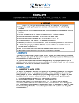
EV130 (door closed) EV130 (door open)
10. This unit is intended for general ventilating only. Do not
use to exhaust hazardous or explosive materials and
vapors. Do not connect this unit to range hoods, fume
hoods or collection systems for toxics.
11. When cutting or drilling into wall or ceiling, do not
damage electrical wiring and other hidden utilities.
12. Use the unit only in the manner intended by the
manufacturer. If you have questions, contact the
manufacturer.
CAUTION
1. To avoid motor bearing damage and noisy and/or
unbalanced impellers, keep drywall spray, construction
dust, etc., out of the unit.
2. Do not connect power to the units external control
terminals: this will damage the unit. The external
terminals are for use only with un-powered controls
designed for low-voltage operation.

SYSTEM LAYOUT
Due to continuing product development, specifications are subject to change without notice
Before you begin
EV70_130_200_300Man_Apr11.docx 134777_011 Revised 04/2011
©
2011 RenewAire LLC Page 2
Read all instructions before installing the unit. Also review
supplemental instructions included with any controls that will
be installed. Carefully unpack and inspect the unit for
shipping damage. Open the access door and inspect inside the
unit. Attach the four duct collars to the unit with the screws
provided in the plastic small-parts bag.
Location of the Unit
Select a location so that:
♦ The fresh air intake vent from the outside is placed a
minimum of ten feet from any other exhaust vent, and is
at least 30” long.
♦ The two ducts to the outside are as short and straight as
possible, for the best performance from the system.
Shorter duct runs help assure that the system is balanced:
the amount of air brought in is equal to the amount of air
exhausted.
♦ The power cord reaches an electrical outlet.
♦ The door can be opened to allow cleaning the core and
filters. Provide at least 24” of clearance at front of unit
for service access to the blowers, filters and energy
exchange core.
♦ The exhaust outlet and fresh air inlet on the outside of the
building should be at least ten feet apart to avoid cross-
contamination. The exhaust duct should be about the
same length as the fresh air duct.
♦ The exhaust outlet should not dump air into an enclosed
space or into any other structure.
♦ Do not install the exhaust outlet and fresh air inlet through
the roof or roof soffit. If these are the only available
options call RenewAire technical support for help.
The preferred mounting location for the unit is on a concrete
foundation wall because the foundation wall will isolate any
blower vibration.
If a basement area is not available or practical, use other
mechanical room space such as a closet, garage, storage, or
accessible attic or crawl space.
NOTE: If you wish to install the unit in an attic or other
unconditioned space, you must insulate all of the unit’s
ductwork that is located in the attic. Use at least R-6
insulation.
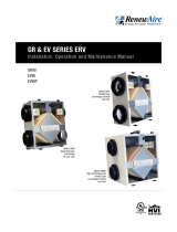
(A) (B)
Separate Room Air Pick-up –
Fresh Air to Furnace Return Air Trunkline Separate Return Air and Fresh Air Supply
Note: ERV Blower may be operated separate from Furnace Blower.
RA
(from bathrooms, kitchen area) FurnaceRA (Furnace)
OA ERV
EA
FA
Living area*
SA
Note: ERV Blower may be operated separate from Furnace Blower
*Use caution to introduce FA at low velocity and where good mixing
will occur to minimize discomfort from drafts.
(C) Furnace Return Air Back Into Return Air
Note: The Furnace Blower must be operated any time the ERV is operated.
Use furnace fan “on” continuous low speed or optional FM control
to cycle furnace fan on with ERV.
(D)
Furnace Return Air Into Furnace Supply Air
(from bathrooms, dining area)
RA
ERV
RA (Furnace)
Note: ERV Blower may be operated separate from Furnace Blower.
RA: Room Air OA: Outside Air FA: Fresh Air
EA: Exhaust Air SA: Supply Air (furnace)
Minimum 3'
Furnace
SA
EA
OA FA
(from bathrooms, dining area)
RA
ERV
RA (Furnace)
Minimum 3'
Furnace
SA
EA
OA FA
RA
ERV
RA (Furnace)
Minimum 3'
Furnace
SA
EA
OA FA
Minimum 3'
Furnace
SA
RA (to ERV)
OA ERV
Minimum 3'
FA
EA
RA (Furnace)
Minimum 3'
Furnace
SA
RA (to ERV)
OA ERV
Minimum 3'
FA
EA
RA (Furnace)
RA (to ERV)
OA ERV
Minimum 3'
FA
EA
RA (Furnace) Furnace
Minimum 3'
Minimum 3'
SA
RA (to ERV)
OA
RA (Furnace)
ERV
EA FA
Install internal
elbow here
Furnace
Minimum 3'
Minimum 3'
SA
RA (to ERV)
OA
RA (Furnace)
ERV
EA FA
Install internal
elbow here

SYSTEM LAYOUT
Due to continuing product development, specifications are subject to change without notice
Exhaust & Outside Air Ducts
The Exhaust Air Duct and the Outside Air Duct connect the
unit to the outside. Flexible insulated duct is typically used.
See Table under “Duct Sizes”, below
Inside Ductwork System
For houses without ducted heating or cooling
systems – see Schematic (B):
EV70_130_200_300Man_Apr11.docx 134777_011 Revised 04/2011
©
2011 RenewAire LLC Page 3
In most houses one or two fresh air grilles in a central part of
the house provide effective distribution of the fresh air into the
home, particularly when the stale exhaust air is picked up at
several points. Because the fresh air is usually somewhat
cooler than the household air, the fresh air supply grilles
should be located in a traffic area like a hallway or stairway
rather than in a sitting area.
If you want to get fresh air into specific rooms with high
occupancy, you can split up the fresh air supply.
For houses with forced-air heating and cooling
systems – see Schematics (A), (C) and (D):
Most units are installed with the fresh air duct connected
directly to a return duct for the main heating and cooling
system. Be careful to connect the fresh air duct at least three
feet from the return plenum to minimize suction from the
furnace blower. A connection closer to the furnace may result
in unbalanced flow and associated problems.
For installations that collect stale air from specific
rooms in the home – for example, Schematics (A)
and (B):
Locate stale air return grills (RA) in rooms where moisture
and odors are generated: bathrooms, the kitchen, and perhaps
other areas where contaminants are generated such as in the
home workshop. Return grills in these other areas may be
dampered so that they can be shut off when not in use. A
central location such as a hallway is also acceptable but won't
clear humidity and odors from baths and kitchens as rapidly.
Locate stale air return grills (RA) near the ceiling on inside
walls. Stale air returns are usually easiest to install in interior
partitions. Put them in the ceiling if that is easier.
Stale Air Return Grill Sizes (8” round on EV300)
Bathroom 4" X 10" or 6" X 10" - 40 to 60 sq. in.
Kitchen 6" X 10" or 60 sq. in.
CAUTION
DO NOT PLACE ANY STALE AIR RETURNS
IN GARAGES.
Can an ERV be used to ventilate bathrooms?
A RenewAire ERV can be used as a central exhaust system in
place of bathroom exhaust fans. Tie a grill in each bathroom
directly back to the ERV – see Schematic (A). A successful
installation should provide at least 50 CFM of exhaust per
moisture producing bathroom. When used for bathroom
exhaust, the EV70 should be used for only one bathroom, the
EV130 should be used for no more than two bathrooms, the
EV200 for up to four bathrooms and the EV300 for up to six
bathrooms. Install a control in each bathroom ventilated by
the ERV (see Secondary Operating Controls, below).
For houses where radon is a concern:
The first line of defense against radon should always be
techniques that prevent the entry of radon into the home, such
as under-slab suction, vented perimeter drainage, and crack
sealing. However, if moderate levels of radon continue to be
present, it is important that the unit slightly pressurize the
basement, not de-pressurize the basement.
Installation of this unit for radon mitigation is beyond the
scope of this manual.
Consult a radon mitigation professional.
Duct Sizes
Duct Minimum Sizes and Type
Exhaust Air & Outside Air
(EA & OA) 6" round insulated duct (8”
round for EV300)
8” round insulated duct may be
used to maintain maximum
airflow
Fresh Air & Stale Air
(FA & RA) 6" round or 8" oval rigid
un-insulated
All ducts from unit to house in unconditioned spaces like
attics and crawl spaces MUST BE INSULATED.
Controls
For an installation in which the ERV should run continuously
in order to provide the required ventilation rate for the home,
no controls are needed. However, in most installations,
control over the unit operation is desired and this is best
provided by a Proportional Timer.
A Dehumidistat is another option but works properly only
during the heating season. If the ERV is used during the
summer, a Proportional Timer should also be installed.
Proportional timers (PT or FM controls) may be located
anywhere that is convenient, but Dehumidistats (DH24) must
be located in the primary living area. A typical location for
either control is next to the home’s thermostat. Proportional
timers operate the ERV to provide regular background
ventilation of the home.
ERV installations that pull stale air from specific rooms, such
as bathrooms, should have Push-button (PB) Controls in
those rooms. The secondary operating controls allow the
system to be turned on from various locations in the house.

INSTALLATION
Due to continuing product development, specifications are subject to change without notice
Mounting the Unit
Unit may be installed in any orientation:
Orient the unit for the simplest duct layout and connections.
Note however that the door is equipped with slide-off hinges.
For the homeowner’s convenience it is helpful to orient the
unit so that the door does not drop off when it is unlatched.
EV70_130_200_300Man_Apr11.docx 134777_011 Revised 04/2011
©
2011 RenewAire LLC Page 4
Mounting the ERV on a concrete foundation wall:
Mount hanging bracket to the wall with appropriate concrete
anchors. Use pre-cut foam tape from small parts bag.
Remove backing and apply two pieces of foam tape equally
spaced along the unit’s mounting flange to be held by the
hanging bracket. Apply the other two pieces of foam over two
holes that will be used for fastening, on the other flange. The
tape should be applied in a “U” shape to cushion both the front
and back of the integral flanges. Lift unit and slide unit flange
into the hanging bracket. Using metal flat washers, fasten
flange opposite hanging bracket to structure. Safety screws
should similarly be installed passing through the hanging
bracket and flange. Make sure the screws, which you must
supply, are properly selected for the loads and substrate
involved.
Mounting the ERV to a stud wall:
Mount unit using supplied hanging bracket kit as described for
mounting to concrete foundation wall. Note that the hole
layout on the integral mounting flanges and the hanging
bracket are spaced for 16” or 24” on-center framing patterns.
Suspending the ERV from floor joists or trusses:
The unit may be screwed directly to joists or trusses using the
hanging bracket and integral flange. Mount as described for
mounting to concrete foundation wall. Note that the hole
layout on the hanging bracket is spaced for 16”, 19.2” and
24”on-center layouts.
CAUTION
RISK OF INJURY WHEN LIFTING UNIT AND
INSTALLING IT OVERHEAD.
GET A HELPER AND WEAR EYE PROTECTION.
Installing Outside Air and Exhaust
Air Ducts:
Ducts connecting the unit to the outside must be well-
insulated. Vapor barrier is required on both inside and outside
of the insulation.
Band or tape inner duct liner to inner flange of appropriate
collar. Drive a sheet metal screw through liner to secure duct
spiral wire to collar. Straighten insulation, and slide outer
duct jacket onto the outer flange of the duct collar. Secure
with band or tape.
CAUTION
The vapor barrier should be continuous and sealed against air
and moisture leakage! If not, condensation or ice may form in
cold weather on the duct surface or in its insulation!
The inlets and outlets should be screened against insects and
vermin and shielded from the weather to prevent the entry of
rain or snow.
CAUTION
INSTALL FRESH AIR INLET AWAY FROM SOURCES
OF CONTAMINANTS.
♦ Do not locate the fresh air inlet where vehicles may be
serviced or left idling.
♦ The fresh air inlet should be at least ten feet away from
any exhaust such as dryer vents, chimneys, furnace, and
water heater exhausts or other sources of contamination or
carbon monoxide.
♦ Never locate the fresh air inlet inside a structure.
Installing Return Air (RA) ducts:
All the stale air returns are connected by ducts to the unit.
Generally, empty stud cavities are used for returns as is often
done with cold air returns for the furnace, using standard duct
boots to connect to six inch pipe at the bottom or top of the
wall cavity. Always be sure to seal all joints with duct sealant
or tape. Some local codes may require metal ducting all the
way from the boots to the stale air grilles. Use rigid ducts to
Foam Tape
Metal Washer
Lag Screw or Concrete
Anchor (provided by others)
Unit Flange
Lag Screw or Concrete
Anchor (provided by others)
Foam Tape
Hanging Bracket
Optional Washer and Screw
(provided by others)

INSTALLATION
Due to continuing product development, specifications are subject to change without notice
Installing Controls
allow the air to move freely and easily through the ducts. See
chart under System Layout to size your ductwork: WARNING
If duct runs are very long (over 25 feet of flex duct for 130
CFM or over 10 feet for 200 CFM each run) or have excessive
bends or elbows or if maximum air flow rates are required,
eight inch insulated flexible duct should be used. The outer
flange of the duct collar can be used for both the inner and
outer jacket of the flexible duct. Care must be taken to insure
that the duct is securely fastened and sealed to the duct collar.
DANGER OF ELECTRICAL SHOCK WHEN
SERVICING AN INSTALLED UNIT.
ALWAYS UNPLUG UNIT BEFORE CONNECTING OR
SERVICING CONTROLS.
Optional controls:
RenewAire offers a variety of controls specifically designed to
work with the EV70/130/200/300 products. These include: PT
(a two wire proportional timer), FM (a six wire proportional
timer that will interconnect with the furnace blower), and PB
(point of use push button control). Other controls that throw an
unpowered switch may also be used.
Do not use more flex duct than necessary!
Flex duct is much more resistant to airflow than rigid duct;
longer runs of flex duct will reduce the ventilation
performance of your system. Stretch flex duct and avoid sharp
bends.
CAUTION Typical control schematic:
EV70_130_200_300Man_Apr11.docx 134777_011 Revised 04/2011
©
2011 RenewAire LLC Page 5
♦ Do not connect Dryers directly to the unit.
♦ Do not connect Range Hoods to the unit. Various wiring designs can be used to properly control the
unit and meet safety and code concerns. Consult your
electrician for an electrical design to meet your needs.
The schematic below shows a typical control system: a PT
proportional timer plus two PB push-button controls.
Installing Fresh Air (FA) ducts:
Use a five foot section of flexible insulated duct to connect the
unit to the ducts at the port labeled Fresh Air to the Inside.
This will cut noise transmitted from the unit. Stretch the flex
duct tightly in order to maintain good airflow.
See installation manuals for the control(s) you select for
wiring diagrams and specific instructions.
If NOT connecting controls to the ERV:
Make a jumper out of a short piece of wire. ERV will run full-
time once its power cord is plugged in.
Starting Up the Unit
♦ Inspect your installation to be sure all duct work is
correctly installed and sealed, that filters are in place, and
controls (if any) are connected.
♦ Shut and latch the door to the unit.
♦ Plug unit into 115 VAC outlet. It may start immediately.
♦ Use control to turn on the unit. Check operation of the
control(s).
♦ Check that the unit’s safety interlock switch turns off the
unit when the door is opened.

PRODUCT DATA
EV70/EV130/EV200/EV300
Energy
Exchange
System:
Cross flow fixed-plate enthalpic energy exchange core: engineered, proprietary resin-media
composite. Provides both sensible and latent heat transfer.
Certified
Performance: See HVI Certified Ratings
Access Door: Front panel opens to provide access to filters, blowers, and heat exchanger. Snap latches and hinges
provided for easy service.
Insulation: One inch foil-faced fiberglass throughout.
Mounting
Options: Unit may be mounted to wall or floor joists using integral mounting flange with hanging bracket kit
provided.
Blower/Motor: A single high efficiency PSC motor directly drives two large diameter centrifugal blowers for quiet
operation.
Filters Cleanable polyester air filters for both exhaust and fresh air streams.
Defrost: Passive frost-free design under most residential conditions. Optional defrost accessory available for
severe applications and climate zones.
Warranty: Ten year limited warranty on energy exchange core; two year limited warranty against defects in
material and workmanship on all other components.
EV70 EV130 EV200 EV300
Airflow
Range: 40-85 CFM for each air
stream. 50-140 CFM for each
air stream. 100-200 CFM each air
stream. 150-300 CFM each
air stream.
Rated Airflow: 70 CFM for each air
stream at 0.2 external
static pressure (ESP).
130 CFM for each air
stream at 0.2” external
static pressure (ESP).
200 CFM for each air
stream at 0.2” external
static pressure (ESP).
300 CFM for each air
stream at 0.4” external
static pressure (ESP).
Dimension: 27 1/8” long x 18 ¼”
wide x 10 5/8” deep
(Not including duct
collars).
28 3/4” wide x 20
1/8” high x 13” deep
(not including duct
collars).
28 3/4” wide x 20
1/8” high x 24” deep
(Not including duct
collars).
28 3/4” wide x 20
1/8” high x 24” deep
(Not including duct
collars).
Unit Weight: 44 lbs. 58 lbs. 80 lbs. 88 lbs.
Duct
Connections: Insulating double
collars with six-
inch/eight-inch round
connections for flexible
or rigid duct work.
Insulating double
collars with six-
inch/eight-inch round
connections for
flexible or rigid duct
work.
Insulating double
collars with six-
inch/eight-inch round
connections for
flexible or rigid duct
work.
Insulating double
collars with 8-inch
oval connections for
flexible or rigid duct
work.
Electrical: Power: .08 HP, 120
Volt, 60 Cycle, single
phase, 0.9 FLA, 84
watts at 73 CFM.
Control: On-board 24
volt transformer and
relay.
Power: 0.1 HP, 120
Volt, 60 Cycle, single
phase, 1.2 FLA, 102
watts at 130 CFM.
Control: On-board 24
volt transformer and
relay.
Power: 0.1 HP, 120
Volt, 60 Cycle, single
phase, 1.5 FLA, 157
watts at 181 CFM.
Control: On-board 24
volt transformer and
relay.
Power: 0.2 HP, 120
Volt, 60 Cycle, single
phase, 3.3 amps, 315
watts at 297 CFM.
Control: On-board 24
volt transformer and
relay.
Due to continuing product development, specifications are subject to change without notice
EV70_130_200_300Man_Apr11.docx 134777_011 Revised 04/2011
©
2011 RenewAire LLC Page 6

PRODUCT DATA
Due to continuing product development, specifications are subject to change without notice
EV70
EV70_130_200_300Man_Apr11.docx 134777_011 Revised 04/2011
©
2011 RenewAire LLC Page 7
EV130
Front View Top View Right View
EV200
Front View Top View Right View
EV300
Front View Top View Right View
Front View Top View Right View

CERTIFIED RATINGS
Due to continuing product development, specifications are subject to change without notice
EV70_130_200_300Man_Apr11.docx 134777_011 Revised 04/2011
©
2011 RenewAire LLC Page 8

CERTIFIED RATINGS
Due to continuing product development, specifications are subject to change without notice
Purpose of your Energy Recovery Ventilation (ERV) System
(continued from page 12)
How much ventilation is right for you? Use your judgment:
Different households require different rates of ventilation,
depending on the pollutants found in each home. Most people
use one of two methods to control the operation of their
ventilation systems:
These guidelines are a starting point. As long as the pollutants
you are concerned with are detectable (like water vapor or
odors) your nose can be a good guide, and you may find that
fewer hours of operation will be sufficient.
For households with smokers:
1. Provide a daily average of 0.35 Air changes per hour (ACH) for
your entire home. A proportional timer is the primary operating
control that allows you to reliably achieve this ventilation rate. Smokers will need at least double the usual ventilation rate to
satisfy non-smokers in the same household.
According to the American Society of Heating, Refrigeration and
Air-Conditioning Engineers (ASHRAE), this ventilation rate will
provide good air quality in most homes for most people.
At this rate, you will be changing the air in your home over eight
times per day. Most ERV systems are generally designed to
provide at least this ventilation rate.
EV70_130_200_300Man_Apr11.docx 134777_011 Revised 04/2011
©
2011 RenewAire LLC Page 9
Be sure to provide at least 15 CFM per person in the home. In
small homes this may mean more than nine air changes per day.
WARNING
There is no known safe level of cigarette smoke.
Any ventilation system may provide noticeable
improvement in spaces where cigarettes are
smoked, but it cannot be expected to protect
against the severe long-term health hazards of
exposure to cigarette smoke.
Or, during the heating season in cold climates:
2. Ventilate enough in the winter to keep indoor humidity low. A
dehumidistat is the primary operating control that allows you to
maintain low winter humidity.
In the winter, water vapor inside your home mostly comes from
people –breathing, showering, and cooking. When the outside air
is 40°F or less, an ERV will reduce indoor humidity. This helps to
prevent condensation on windows.
High wintertime humidity generally means you need more
ventilation to control other indoor-air pollutants, like cooking odors.

EV70_130_200_300Man_Apr11.docx 134777_011 Revised 04/2011
©
2011 RenewAire LLC Page 10
EV70 EV130
A. Label
B. Energy Exchange Core
C. Interlock switch
D. E-box and control kit
E. E-box
F. Control board with standoffs
G. Blower assembly (complete)
H. Motor
I. Blower & wheel, divider side
J. Door assembly
K. Hinge set (both parts)
L. Terminal strip
M. Line cord with bushing
N. Filter (set of two)
P. Core cross bar
Q. Core gasket kit (not shown)
R. Hanging bracket kit
S. Divider cross bar
T. Hardware kit
U. Blower & wheel, motor side
V. Duct collar (sold singly; 4 per unit)
W. Latch set (both parts)
X. Case, insulated, without door
Y. Literature packet
Z. Filter Clip (EV130 only; sold
singly; 2 per unit)
SERVICE PARTS

Due to continuing product development, specifications are subject to change without notice
EV70_130_200_300Man_Apr11.docx 134777_011 Revised 04/2011
©
2011 RenewAire LLC Page 11
EV200 EV300
A. Label
B. Energy Exchange Core
C. Interlock switch
D. E-box and control kit
E. E-box
F. Control board with standoffs
G. Blower assembly (complete)
H. Motor
I. Blower & wheel, divider side
J. Door assembly
K. Hinge set (both parts)
L. Terminal strip
M. Line cord with bushing
N. Filter (set of two)
P. Core cross bar
Q. Core gasket kit (not shown)
R. Hanging bracket kit
S. Divider cross bar
T. Hardware kit
U. Blower & wheel, motor side
V. Duct collar (sold singly; 4 per unit)
W. Latch set (both parts)
X. Case, insulated, without door
Y. Literature packet
Z. Filter Clip (sold singly; 4 per unit)

USE & MAINTENANCE
Due to continuing product development, specifications are subject to change without notice
Maintenance Requirements
Keep your ERV performing at its best by cleaning
it as described below:
EV70_130_200_300Man_Apr11.docx 134777_011 Revised 04/2011
©
2011 RenewAire LLC Page 12
WARNING
RISK OF ELECTRIC SHOCK OR INJURY.
♦ Before servicing or cleaning the unit, unplug the unit line
cord.
♦ Make sure unit is not running before opening its door.
Blower wheels are sharp and can cut.
♦ Do not disable the interlock switch: it is there for your
safety.
Service filters regularly:
Service filters every three months when the unit is in regular
use or as needed to keep them reasonably clean.
1. Release cam latches and carefully swing access door
open. Remove the door by sliding to one side.
2. In EV130/200/300, remove filter clips.
3. Pull the filters out.
4. Vacuum with a hose attachment.
5. Re-install filters and filter clips, (see illustrations,
page 7).
6. Re-install door, and fasten cam latches.
NOTE: The filters should be replaced after they have been
cleaned several times. The primary contact for replacement
filters for your RenewAire unit is the installing contractor. As
an alternative, you may wish to produce your own filters.
Please follow these instructions:
Filters may be cut from a sheet or roll of ¾” - 1” firm, spun
polyester filter “hog hair” media or material, similar to the
existing filter in the residential unit.
The size of each filter (2 required per unit) is as follows:
EV70 7” x 10 ½”
EV130 10 ½” x 10 ½”
EV200/EV300 10 ½” x 21 ¾”
Call your HVAC contractor or RenewAire for further
information.
NOTE: Filters must be used or the face of the energy
exchange core will become blocked by dust. The filters
supplied in the unit are usually able to keep the energy
exchange core clear for many months. Finer filters can be
used but must be cleaned more often.
Clean the face of the energy exchange core yearly:
1. Remove the filters (see above).
2. Vacuum the exposed faces of the energy exchange
core with a soft brush attachment.
3. After servicing the filters, re-install them (see above).
4. Vacuum out dust from the rest of the unit case.
Dust collects only on the entering faces of the energy
exchange core. The interior of the energy exchange core stays
clean even if the core faces are dust covered.
CAUTION
DO NOT WASH THE ENERGY EXCHANGE CORE.
Clean only as described above. The energy exchange core can
be replaced but is expensive.
The blower/motor package needs no lubrication:
Vacuum clean the blower wheels at the same time you clean
the face of the energy exchange core.
Purpose of an Energy Recovery
Ventilation (ERV) System
Many modern homes are built air-tight for energy efficiency
and comfort. The result is that natural air infiltration rates are
often too low to provide acceptable indoor air quality. The
solution is to use an ERV to remove gaseous pollutants such
as odors, winter-time excess humidity, formaldehyde, smoke,
radon, vapors from cleaning products, and other chemicals.
The removal of dust and other small particles from your home
is not the function of an ERV.
When should you use your ERV?
Use your ERV when windows are closed and you need to
ventilate. When the outdoor air is warmer or cooler than
comfortable, the ERV will allow a quieter, more secure home
with the windows closed and will also save energy.
Using an ERV with air-conditioning:
An ERV works very well with air-conditioning, because its
“enthalpy-transfer” energy-exchange core will reduce the
amount of moisture in the outside air that is brought in. ERVs
are the preferred way to ventilate while air-conditioning
because it brings in less moisture than any other ventilation
method.
Controlling excess humidity during cold weather:
When the ERV is first turned on at the beginning of the
heating season (or when first installed), it will have to run full-
time for several days to reduce indoor humidity levels. A
properly set dehumidistat will do this automatically. If your
control is the proportional timer type (PT or FM), it should be
set to “100%” for several days whenever you have a problem
with excess humidity during cold weather.
(Continued on page 9)
/