

VMAC – Vehicle Mounted Air Compressors
Toll Free: 1-888-241-2289
Fax: 1-250-740-3201
1
VR LITE AIR COMPRESSOR
OWNERS MANUAL
General Information..................................................................... 4
Introduction ............................................................................... 4
Ordering Parts .......................................................................... 4
Safety Messages ...................................................................... 4
Important Safety Notice ............................................................ 5
Safety Precautions ................................................................... 7
Personal Hazards ..................................................................... 8
System Identification and Warnings.......................................... 9
System Specifications ................................................................ 10
System Components ................................................................... 11
WHASP Tank ........................................................................... 11
Compressor .............................................................................. 12
Control Panel ............................................................................ 12
Throttle control .......................................................................... 13
Hoses ....................................................................................... 13
Operating Principles.................................................................... 14
Oil Separation and Cooling ...................................................... 14
Filtration .................................................................................... 15
Belt Alignment and Tensioning ................................................. 15
Pressure Regulation and Engine Speed Control ..................... 16
Safety Devices .......................................................................... 17
Hose Protection ........................................................................ 17
System Operation ........................................................................ 18
Control Box Features................................................................ 18
Automatic Over-Temperature Shutdown .................................. 18
Operating Instructions .............................................................. 19
Cold Environment Operation .................................................... 20
Diesel Particulate Filter Warning (DPF) ................................... 20
Stationary Elevated Idle Control (Ford Applications Only) ..... 21
SEIC Restart Delay .................................................................. 21

VMAC – Vehicle Mounted Air Compressors
Toll Free: 1-888-241-2289
Fax: 1-250-740-3201
2
Problem Diagnostics and Troubleshooting .............................. 22
Maintenance.................................................................................. 25
Routine Maintenance ................................................................ 25
Maintenance Schedule ............................................................. 25
Oil Level Maintenance .............................................................. 26
Inspecting the Drive Belt ........................................................... 27
Inspecting the Muffler ................................................................ 27
Inspecting the Pressure Relief Valve ........................................ 27
Replacing the Air Filter .............................................................. 28
Replacing the Oil Filter .............................................................. 29
Changing Compressor Oil ......................................................... 31
Changing the Coalescing Filter ................................................. 32
Setup, Performance Testing, and Adjustments ........................ 33
Adjusting the System .................................................................. 34
For Ford vehicles equipped with SEIC: .................................... 34
For all other vehicles: ................................................................ 35
Adjusting the Pressure Switch .................................................. 36
Recommended Accessories ....................................................... 37
Auxiliary Air Receiver .................................................................. 38
Accessory Products from VMAC ................................................ 39
VMAC Warranty ............................................................................ 40
1. General Provisions and Limitations: ................................. 40
2. No warranty is made with respect to: ................................ 40
3. Warranty Period: ............................................................... 41
4. VMAC Obligations: ............................................................ 42
5. Buyer Obligations: ............................................................. 42
6. Warranty Registration Validation: ..................................... 42
7. Disclaimer and Warranty Service: ..................................... 43

VMAC – Vehicle Mounted Air Compressors
Toll Free: 1-888-241-2289
Fax: 1-250-740-3201
3
Owner Manual - Document #1930246
VR LITE Systems
Changes and Revisions
Version
Revision Details
Revised by /date
Checked by /date
Reviewed by /date
Implemented
A
15-072
RF June 17 2015
RD June 17 2015
SC June 17 2015
June 22 2015
B
C
D
The information in this manual is intended for certified VMAC installers
who have been trained in installation procedures and for people with
mechanical trade certification who have the tools and equipment to
properly and safely perform the installation. Do not attempt this
installation if you do not have the appropriate mechanical training,
knowledge and experience.
Follow all safety precautions for mechanical work. Any grinding,
bending or restructuring operations for correct fit in modified trucks must
follow standard shop practices.
The VMAC warranty form must be completed and mailed or
faxed to VMAC at the time of installation for any subsequent
warranty claim to be considered valid.
The VMAC warranty form is located online at:
http://vmacair.com/support/warranty/
This warranty form must be completed and mailed or faxed to VMAC at
the time of installation for any subsequent warranty claim to be
considered valid.
To order parts, contact your VMAC dealer. Your dealer will ask for the
VMAC serial number, part number, description and quantity. To locate
your nearest dealer, call 1-800-738-8622 or online at www.vmacair.com
Copyright 2015
All trademarks used in this manual are the property of the respective copyright holder.
The contents of this manual may not be reproduced in any form without the express
written permission of VMAC, 1333 Kipp Road, Nanaimo, BC V9X 1R3.
Printed in Canada

VMAC – Vehicle Mounted Air Compressors
Toll Free: 1-888-241-2289
Fax: 1-250-740-3201
4
General Information
Introduction
This manual provides operation instructions, specifications, adjustment,
maintenance, and warranty information for the VMAC VR LITE
UNDERHOOD air compressor.
Ordering Parts
To order parts, contact your VMAC dealer. Your dealer will ask for the
VMAC serial number, part number, a description of the part and the
quantity. To locate your nearest dealer, call 1-800-738-8622.
Safety Messages
This symbol is used to call your attention to instructions
concerning your personal safety. Watch for this symbol; it
points out important safety precautions, it means “attention,
become alert!” Your personal safety is involved. Read the
message that follows and be alert to the possibility of
personal injury or death. Be alert; your safety is involved.
While it is impossible to warn about every conceivable
hazard, let good common sense be your guide.
This symbol is used to call your attention to instructions on a
specific procedure that if not followed may damage or
reduce the useful life of the compressor.
This symbol is used to call your attention to additional
instructions involving fire hazards.
This symbol is used to call your attention to additional
instructions involving explosion hazards.

VMAC – Vehicle Mounted Air Compressors
Toll Free: 1-888-241-2289
Fax: 1-250-740-3201
5
Important Safety Notice
The information contained within this manual is based on sound
engineering principles, research, extensive field experience and
technical information. Information is constantly changing with the
addition of new models, assemblies and service techniques. If a
discrepancy is noted in this manual, contact VMAC prior to initiating or
proceeding with service. Current information may clarify the matter. Any
person with knowledge of such discrepancies who performs any work on
the system, service and repair assumes all risks.
Only proven service procedures are recommended. Anyone who departs
from the specific instructions provided in this manual must first assure
that their safety and that of others is not being compromised and that
there will be no adverse effects on the performance or the operational
safety of the equipment.
Read this information before operating the compressor for the first time.
Follow the information and procedures in this manual for operation,
maintenance and repair. Observe the following items to reduce the
chance of personal injury or equipment damage.
Follow all safety precautions for mechanical work. Moving fan belts and
fan blades are an extreme hazard. Stay clear of all moving parts when
the system is operating. Only qualified personnel should perform
maintenance and repair on system components and only while the
system is properly shut down.
Proper service and repair are important to the safety of the service
technician and the safe, reliable operation of the equipment. Always use
genuine VMAC replacement parts; do not use any substitutes.
The procedures described in this service manual are effective methods
of service and repair. Some procedures may require the use of tools
specially designed for a specific purpose. Anyone using a replacement
part, service procedure or tool must first determine that neither their
safety nor the safe operation of the equipment will be compromised by
the replacement part, service procedure or tool selected.

VMAC – Vehicle Mounted Air Compressors
Toll Free: 1-888-241-2289
Fax: 1-250-740-3201
6
This manual contains various warnings, cautions and notices that must
be observed to reduce the risk of personal injury during service or repair
and the possibility that improper service or repair may damage the
equipment or render it unsafe. Be aware that it is impossible to warn of
all the possible hazardous consequences that might result from failure to
follow these instructions.
VMAC will not be held responsible for any liability, injuries, loss or
damage to individuals or to equipment as a result of the failure of any
person to properly adhere to the procedures set out in this manual or
standard safety practices. Safety should be your first consideration in
performing service operations. If you have any questions concerning the
procedures set out in this manual or require any more information on
details that are not included in this manual, please contact VMAC before
beginning any work.
Fire in the compressor system can cause an explosion
and flame projection. Should this occur, there is
potential for serious injury or death.
Vaporized oil propelled by high-pressure air is an
explosive mixture.

VMAC – Vehicle Mounted Air Compressors
Toll Free: 1-888-241-2289
Fax: 1-250-740-3201
7
Safety Precautions
Avoid all contact with pressurized air, if it penetrates your
skin it can enter your bloodstream and cause serious
bodily harm or even death. Do not breathe the
compressor air. Vaporized oil is a severe respiratory
hazard.
Vaporized oil propelled by high pressure air is an
explosive mixture. To prevent compressor explosion or
fire, make sure that the air entering the compressor is
free of flammable vapors
Observe the following general safety rules:
Pay attention to operations; do not leave the vehicle
unattended.
Follow safe work practices and wear the appropriate safety
equipment when operating air-powered equipment, particularly
eye and hearing protection.
Avoid contact with drive belts and stay clear of all moving parts
when the system is operating.
Follow all safety precautions for under hood mechanical work.
Follow safety procedures for the type of work being completed.
Observe these rules when operating the compressor:
Do not bypass or disable the oil temperature sensor.
Do not expose the tank or compressor to extreme heat.
Do not perform any service until the system has been
completely depressurized and you have verified that all air has
been discharged from the compressor system and any
connected receiver tanks.
Do not try to repair or service a pressurized system
Maintenance and repair on system components should only be
performed by qualified personnel
The vehicle must be in park (for automatic transmissions) or
neutral (for manual transmissions) with the park brake fully
applied before starting the compressor and at all times during
compressor operation
Use a regulator in the output line to precisely control the final air
delivery pressure
Do not bypass the park brake or DDC (drive disable circuit)
connections
Do not operate the compressor while driving
Do not tamper with or remove the pressure relief valve

VMAC – Vehicle Mounted Air Compressors
Toll Free: 1-888-241-2289
Fax: 1-250-740-3201
8
Personal Hazards
Follow all safe work practices. Wear the appropriate safety
equipment.
Do not breathe the compressor air. Vaporized oil is a
respiratory hazard.
Always use the appropriate personal protective
equipment, particularly eye and hearing
protection when operating air-powered
equipment.
The compressor system is under sufficient
pressure that a leak could force the air/oil mixture
through the skin directly into your bloodstream.
This could cause serious injury or death.
Never adjust or attempt to make any repairs to the
system while the engine is running. Components and
hoses under pressure could fail and cause serious
injury or death.
Never perform maintenance procedures on the system
until the compressor has been shut down for at least 5
minutes to ensure the system is fully depressurized.
After 5 minutes open the discharge valve to ensure the
system is depressurized. Failure to depressurize the
system could cause parts to separate explosively.
Flying parts could cause serious injury or death.
Air/oil mixture could be sprayed out with sufficient
force to penetrate the skin, which could cause serious
injury or death.
The engine, exhaust and the compressor system get
very hot during operation, contact with the
components or the oil can cause serious burns. Allow
sufficient time for the system to cool before
performing service.
Components and hoses under pressure could separate
suddenly, fly out and cause serious injury or death. If
equipped, the auxiliary air tank must be drained before
servicing any components in the compressor system

VMAC – Vehicle Mounted Air Compressors
Toll Free: 1-888-241-2289
Fax: 1-250-740-3201
9
System Identification and Warnings
Ensure that the safety and operational instruction decal is affixed in an
obvious location so that it can be seen by vehicle operators. A good spot
for this is usually on the inside of the door, on the panel underneath the
steering wheel, or next to the compressor control panel.
To alert any technicians that may service the vehicle, affix the servicing
caution/contact label in the engine compartment near the hood latch in a
visible location. Thoroughly clean the selected area before affixing the
label

VMAC – Vehicle Mounted Air Compressors
Toll Free: 1-888-241-2289
Fax: 1-250-740-3201
10
System Specifications
Model:
VR LITE UNDERHOOD Air Compressor
Compressor Type:
Oil injected rotary screw
Drive System:
Front End Auxiliary Drive (FEAD)
Control:
Electric on/off 12V clutch control
Maximum Air Delivery:
Up to 35 CFM and 175 PSI depending on installation and
engine speed
Pressure Regulation:
Compressor clutch engages/disengages in response to air
demand
Engine Controls:
End user adjustable single speed throttle control
Elevated idle in response to air demand
Safety Features:
200 PSI (1380 kPa) relief valve in separator tank
thermostatic switch
rapid blow-down valve to relieve system pressure on shutdown
Lubrication:
VMAC certified and approved synthetic oil
Filters:
Air filter: paper-type replaceable
Oil filter: spin-on type high pressure
Coalescing filter: spin-on type

VMAC – Vehicle Mounted Air Compressors
Toll Free: 1-888-241-2289
Fax: 1-250-740-3201
11
System Components
The VR Lite consists of the following components:
WHASP tank (Waste Heat Air Separation Package)
Compressor
Control panel
Throttle control
Air/oil discharge hose
Oil return hose
1/4” scavenge oil return line
WHASP Tank

VMAC – Vehicle Mounted Air Compressors
Toll Free: 1-888-241-2289
Fax: 1-250-740-3201
12
Compressor
Control Panel

VMAC – Vehicle Mounted Air Compressors
Toll Free: 1-888-241-2289
Fax: 1-250-740-3201
13
Throttle control
Ford applications with the SEIC may have a different
style of throttle control module. See Section: Setup,
Performance Testing, and Adjustments for more
information.
Hoses
The VR Lite has three main hoses:
#8 (1/2” ID) discharge hose
#6 (3/8” ID) oil return hose
1/4” OD PTFE scavenge oil return line
Compressor oil will degrade rubber lined hoses, use only
hoses with an AQP Elastomer type liner. Ensure any
replacement hoses used are compatible with the VMAC
compressor oil. Contact VMAC at 1-888-241-2289 for
further information.

VMAC – Vehicle Mounted Air Compressors
Toll Free: 1-888-241-2289
Fax: 1-250-740-3201
14
Operating Principles
Air Compression
The VR-Lite systems use a VMAC designed and built flooded-lobe,
rotary screw compressor. The oil-filled compressor housing contains
two rotors.
Compression occurs when inlet air (at normal atmospheric pressure)
enters a chamber where it is trapped between meshing rotor lobes.
Cooled oil is injected into the rotors during compression to lubricate the
rotors and bearings, absorb the heat of compression, and seal the rotor
lobes to allow for efficient compression. As the rotors rotate, the
meshing lobes compress the volume of the trapped air/oil mixture before
sending it down the discharge line to be cooled and separated by the
WHASP tank.
Oil Separation and Cooling
The system uses a WHASP (Waste Heat Air Separation Package) tank
combined 2-stage air/oil separator and oil cooler. The hot air/oil mixture
from the compressor enters the cooler on the top of the tank, where the
mixture is cooled and the majority of the oil separates from the air (first
stage separation) and settles into the reservoir tank below the cooler.
The cooled oil then passes through a high-pressure oil filter before being
returned to the compressor via the oil return line. The remaining oil mist
and fine droplets are removed from the air by passing it through a
coalescing filter (second stage separation). Oil removed by the
coalescing filter is collected and returned to the compressor via the 1/4”
scavenge line.
The WHASP tank contains an integrated minimum pressure check valve
(MPCV) to ensure a minimum pressure of approximately 60 PSI (410
kPa) is maintained in the tank to ensure proper oil flow while the clutch is
engaged and the system is compressing air. Air will not flow out of the
WHASP tank until this pressure is reached. The MPCV is factory set and
requires no adjustment or servicing. Due to the integrated check valve
no separate check valve is required or recommended when connecting
the WHASP tank output to a receiver tank.

VMAC – Vehicle Mounted Air Compressors
Toll Free: 1-888-241-2289
Fax: 1-250-740-3201
15
Filtration
VMAC rotary screw compressors are designed and machined to
exacting tolerances. Foreign particles entering the compressor can
damage system components such as seals, bearings, rotors, and the
inside of the housing resulting in efficiency and performance losses and
reduced system life expectancy.
The system is equipped with a replaceable paper element air inlet filter,
spin-on high pressure oil filter and a spin-on coalescing filter.
These system filters enhance performance and extend component life
by reducing damage from dust and other debris. Proper maintenance is
the key to long compressor system life.
Belt Alignment and Tensioning
Depending on the application, the VR LITE system may be driven by
either the OEM FEAD serpentine belt, or its own dedicated serpentine
belt. Depending on the particular system the compressor may be driven
by a belt with 8 ribs or less. For proper alignment always ensure the belt
is centered on the clutch grooves, i.e. if the system uses a 4-rib
serpentine belt it should be centered on the middle 4 grooves with 2
unused grooves showing on either side of the belt.
For systems driven by the OEM FEAD serpentine belt, the compressor
mounts and is driven in the same manner as a typical optional second
alternator. The OEM belt may be replaced with a longer belt if required
and the OEM belt tensioning system is retained. Belt maintenance and
service should be performed per the OEM’s maintenance schedule.
Systems with a dedicated serpentine auxiliary FEAD belt are equipped
with an automatic tensioner and do not require manual adjustment.
Check pulley alignment to ensure proper belt operation.
Additional Belt Information
Where necessary, VMAC provides a replacement for the OEM FEAD
belt in the compressor kit. The OEM belt and any brackets removed
during compressor installation should be kept with the vehicle. In the
event of a compressor failure, the VMAC supplied belt and brackets can
be replaced with the OEM belt and brackets to ensure the vehicle
remains operable. See the installation manual for specific belt
replacement instructions.

VMAC – Vehicle Mounted Air Compressors
Toll Free: 1-888-241-2289
Fax: 1-250-740-3201
16
Pressure Regulation and Engine Speed
Control
The system uses a minimalistic control circuit. A pressure switch and
thermostatic switch provide signals to the compressor clutch and throttle
control. When discharge pressure drops below the pressure switch cut-
in pressure, the system engages the clutch and commands the engine to
increase to its high idle speed. When the pressure increases to the cut-
out pressure, the clutch disengages and the engine drops to base idle.
These control devices provide the following benefits:
quick response to air flow demands
reduction of standby noise
reduction of cooling system load
fuel conservation when not using air
The engine speed set-point and the pressure switch cut-out set-point are
adjustable. Higher engine speed will yield higher compressor output, but
with the penalty of increased fuel consumption.
For information on adjustment, please refer to the section titled
“Adjusting the System”
An external regulator is required for operation at tool pressures lower
than 100 PSI (690 kPa).

VMAC – Vehicle Mounted Air Compressors
Toll Free: 1-888-241-2289
Fax: 1-250-740-3201
17
Safety Devices
A 200 PSI (1380 kPa) pressure relief valve is installed in the WHASP
tank to prevent system over pressure (refer to tank diagram on page 9).
The system is also equipped with an automatic rapid blow-down system
to discharge system pressure on shutdown.
The system makes use of the OEM safety circuits when available, or
adds safety circuits where required. These circuits prevent the operation
of the high idle system if certain conditions are not met. This both
protects the vehicle, and ensures that the engine will not automatically
go to high idle, should the compressor system be inadvertently activated
at an inappropriate time.
The compressor system is equipped with a thermostatic switch which
disengages the compressor clutch and drops the engine to base idle,
should the air/oil temperature increase above a safe level. An indicator
light on the control box will illuminate to show that an over-temperature
event has occurred.
A 20A fuse protects the system. If the fuse blows
continuously, there is an electrical problem that will
not be solved by a higher fuse rating. Exceeding the
rating can cause component damage.
Do not disable or bypass the over-temperature
shutdown circuit. Failure of the shutdown system
could result in equipment damage, injury or death.
Hose Protection
To prevent damage to the lines, observe the following:
Always ensure that the hoses are secure, do not allow the
hoses to dangle under the vehicle
Always ensure that the hoses do not get pinched in steering
or suspension components
Make sure to keep the hoses away from hot surfaces, such
as turbocharger housings or exhaust system components
Hoses should not be bent tightly around sharp metal edges
Ensure that hoses are kept away from fan blades or belts
If the hoses are secured in a bundle, protect them from
abrasion by insulating them from each other using rubber
padding or plastic loom
If any hoses appear damaged, replace hoses prior to failure.

VMAC – Vehicle Mounted Air Compressors
Toll Free: 1-888-241-2289
Fax: 1-250-740-3201
18
System Operation
Control Box Features
The control panel is not weather-proof. It should be
installed either inside the cab or inside a cabinet on the
service body (if equipped).
The control box has the following features:
On/off toggle switch with green indicator light
Compressor hour meter display
Over-temperature warning light
Automatic Over-Temperature Shutdown
If the compressor oil temperature exceeds 140 oC (290 oF), the
thermostatic switch will disengage the compressor clutch, preventing
operation of the system. The cooling fan will remain running.
The warning light on the control box will illuminate to inform you of the
over-temperature situation. The control system will prevent the
compressor from automatically re-starting. The system must be switched
off and back on again to clear the over-temperature code.
If the oil has cooled to a safe temperature, the system will be ready to
restart.
Hour
Meter

VMAC – Vehicle Mounted Air Compressors
Toll Free: 1-888-241-2289
Fax: 1-250-740-3201
19
Operating Instructions
The vehicle must not be parked on grades exceeding 20 º
in slope as this may affect lubrication and air/oil
separation.
1. Place the manual transmission in neutral or the automatic
transmission in park and fully apply the park brake.
2. Start and run the vehicle long enough for the engine to stabilize at
base idle and reach normal operating temperature.
3. Close the hood (if open).
4. Close all compressor air system outlets.
5. Activate the compressor using the toggle switch on the control
panel.
Engine RPM will increase to the set speed. A brief hissing of air from the
blow down muffler on the cooler/separator tank, terminated by an
audible “clunk” noise is normal. The hissing may occur for 1 to 20
seconds, depending on component and ambient temperature and
receiver tank pressure. The system will build pressure until it reaches
150 PSI (less if the pressure set-point has been reduced). The clutch will
disengage, and the cooler/separator tank will blow-down. The engine will
drop to base idle.
Re-starting the compressor immediately after shutdown
may cause belt slippage and compressor clutch damage.
Page is loading ...
Page is loading ...
Page is loading ...
Page is loading ...
Page is loading ...
Page is loading ...
Page is loading ...
Page is loading ...
Page is loading ...
Page is loading ...
Page is loading ...
Page is loading ...
Page is loading ...
Page is loading ...
Page is loading ...
Page is loading ...
Page is loading ...
Page is loading ...
Page is loading ...
Page is loading ...
Page is loading ...
Page is loading ...
Page is loading ...
Page is loading ...
Page is loading ...
Page is loading ...
Page is loading ...
Page is loading ...
-
 1
1
-
 2
2
-
 3
3
-
 4
4
-
 5
5
-
 6
6
-
 7
7
-
 8
8
-
 9
9
-
 10
10
-
 11
11
-
 12
12
-
 13
13
-
 14
14
-
 15
15
-
 16
16
-
 17
17
-
 18
18
-
 19
19
-
 20
20
-
 21
21
-
 22
22
-
 23
23
-
 24
24
-
 25
25
-
 26
26
-
 27
27
-
 28
28
-
 29
29
-
 30
30
-
 31
31
-
 32
32
-
 33
33
-
 34
34
-
 35
35
-
 36
36
-
 37
37
-
 38
38
-
 39
39
-
 40
40
-
 41
41
-
 42
42
-
 43
43
-
 44
44
-
 45
45
-
 46
46
-
 47
47
-
 48
48
Ask a question and I''ll find the answer in the document
Finding information in a document is now easier with AI
Related papers
-
 Vmac A700219 Installation guide
-
 Vmac A700243 Installation guide
-
 Vmac V300012 Installation guide
-
 Vmac V300011 Installation guide
-
 Vmac A700233 Installation guide
-
 Vmac G300001 Owner's manual
-
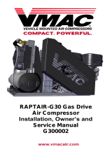 Vmac RAPTAIR-G30 Installation guide
-
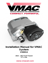 Vmac V300014 Installation guide
-
 Vmac V900125 Installation guide
-
 Vmac A700153 Installation guide


