Page is loading ...

© 2023 NXP B.V.
S32G-VNP-GLDBOX3 User Guide
NXP Semiconductors
Document Number: S32G-VNP-GLDBOX3UG
User's Guide
Rev. 1.0
,
03/2023

S32G-VNP-GLDBOX3 User Guide, Rev. 1.0, 03/2023
2 NXP Semiconductors
Chapter 1
Get To Know S32G-VNP-GLDBOX3
1.1 S32G-VNP-GLDBOX3 Board Overview
The S32G-VNP-GLDBOX3 is a compact, highly-optimized and integrated reference design board
featuring the S32G399A Vehicle Network Processor. This board provides reference for various typical
automotive applications such as:
• Service-oriented gateway
• High-performance central compute unit
• Safety checker for ADAS and autonomous driving
• Black-box for vehicle data logging
• Automotive access point
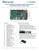
Figure 1.1 shows the board overview of S32G-VNP-GLDBOX3.
Figure 1.1 S32G-VNP-GLDBOX3 board overview

S32G-VNP-GLDBOX3 User Guide, Rev. 1.0, 03/2023
NXP Semiconductors 3
1.2 S32G-VNP-GLDBOX3 Block Diagram
Figure 1.2 shows the block diagram of S32G-VNP-GLDBOX3.
S32G399A
20 MB Internal RAM
4 x Cortex-M7 LS, Up to 400 MHz
4 x Cortex-A53 LS / 8 x Cortex-A53, Up to 1.3 GHz
QSPI Flash
512M-bit
200MHz
LPDDR4
32G-bit
SD Card eMMC
32G-Byte
RTC
PCA85073A
LIN Phy
(Master Mode)
Gigabit Eth.
Phy
AR8035
Gigabit Eth.
Phy
KSZ9031
Gigabit Eth.
Phy
KSZ9031
Gigabit Eth.
Phy
AR8035
Eth. Switch SJA1110
Eth. Phy
LIN Phy
TJA1021
(Slave Mode)
FlexRay Phy
TJA1081 UART-USB
FT232
Boot mode
select circuit Parallel RCON
select circuit
PMIC
VR5510
USB 2.0 Phy
USB83340
CAN Phy
TJA1043
6 pcs
UART-USB
FT232
CAN Phy
TJA1463
6 pcs
CAN Phy
TJA1153
4 pcs
CAN Phy
TJA1043
2 pcs
PMIC
FS5600
PMIC
PF5300
PMIC
PF5020 PMIC
PF5020 Load
Switch
GMAC0 PFE_MAC2 SerDes1SerDes0
100Base-T1 Phy x6100Base-Tx Phy
100Base-T1
x6-ch
100Base-Tx
Port 2 Port 3
RGMII RGMII
PCIe x2 PCIe x2
RGMII RGMII
uSDHC I/F LINFlex 2GPIO Flex CAN LINFlex 1 LINFlex 0 ULPIADC
IO Expander
PCAL6524H
SGMII PCIe x1
SGMII
1000Base-T Port M.2 slot E-key M.2 slot M-key PCIe x1 socket
100Base-T1 Port
100Base-TX Port 1000Base-T Port 1G / 2.5GBase-T Port
USB PortUART0 PortUART1 PortAutomotive Bus PortMulti-Function PortSD Card Port12V DC Power Supply Input Port
ADC
x5ch GPIO
x6 Flex LIN
x1ch LLCE LIN
x4ch LLCE CAN
x6ch LLCE CAN
x4ch LLCE CAN
x6ch Flex CAN
x2ch
FlexRay
x1ch
S32G Aurora Port
S32G JTAG Port
SJA1110 JTAG Port
LLCE LIN LLCE FlexRay LLCE CAN LLCE CAN LLCE CAN
Clock generator
Si5332
Port 4Port 1
SerDes
multiplex circuit
PCIe x2 SGMII
Figure 1.2 S32G-VNP-GLDBOX3 block diagram
1.3 S32G-VNP-GLDBOX3 Hardware Resources
The resources of S32G-VNP-GLDBOX3 are listed as below:
• Processor
➢ 8x Arm Cortex-A53 cores (with optional cluster lockstep)
➢ 4x dual-core lockstep Arm Cortex-M7 cores
➢ Hardware Security Engine (HSE)
➢ CAN, LIN and FlexRay offload with Low Latency Communications Engine (LLCE)
➢ Gigabit Ethernet Packet Forwarding Engine (PFE)
➢ 20 MB Embedded System RAM with ECC
➢ 32KB Standby RAM with ECC
• External Storage
➢ 1x on-board NOR Flash memory (64MB)
➢ 1x SD card slot
➢ 1x on-board eMMC (32GB)
➢ 1x on-board LPDDR4 (4GB)

S32G-VNP-GLDBOX3 User Guide, Rev. 1.0, 03/2023
4 NXP Semiconductors
• Ethernet—12ports
➢ 1x 100BASE-TX
➢ 6x 100BASE-T1
➢ 4x 1000BASE-T
➢ 1x 1G/2.5GBASE-T
• PCIe
➢ 1x M.2 M-key slot*
➢ 1x M.2 E-key slot*
➢ 1x PCIe x1 socket
• LIN
➢ 4x LLCE LIN
➢ 1x LINFlexD
• CAN/CAN FD
➢ 16x LLCE CAN/CAN FD
➢ 2x FlexCAN /CAN FD
• FlexRay
➢ 1x LLCE FlexRay
• USB
➢ 1x USB 2.0 I/F Host/Device mode
• Scalable interface
➢ 1x DSPI
➢ 5x ADC
➢ 1x I2C
➢ 1x WKUP
• RTC
➢ Support on-board external RTC
• Debug
➢ 1x 20-pin JTAG for S32G
➢ 1x 10-pin JTAG for SJA1110A
➢ 1x Aurora Trace
➢ 2x UART
Note
Only one of the M.2 M-key slot and E-key slot can be used at a time.

S32G-VNP-GLDBOX3 User Guide, Rev. 1.0, 03/2023
NXP Semiconductors 5
Chapter 2
S32G-VNP-GLDBOX3 Hardware Package
2.1 Hardware Package Overview
This section describes hardware package of S32G-VNP-GLDBOX3. Hardware and accessories are shown
in the figure 2.1.
Figure 2.1 S32G-VNP-GLDBOX3 hardware and accessories
2.2 Hardware Connection Instruction
To connect any cables to S32G-VNP-GLDBOX3, follow the instructions shown in figure 2.2.
J53 cable connection (100BASE-T1)
P5 cable connection (1G/2.5GBASE-T)
P4 cable connection (100BASE-TX)
P3, P2 cable connection (1000BASE-T)
UART cable connection(UART0, UART1)
J6 cable connection (LLCE CAN, FlexCAN, FlexRay)
J5 cable connection(LLCE LIN, LINFlexD, ADC, I2C, DSPI, WKUP, Power supply)
UART0 UART1 J6 J5
J53 P5 P4
P3 P2
Figure 2.2 S32G-VNP-GLDBOX3 hardware connection instruction

S32G-VNP-GLDBOX3 User Guide, Rev. 1.0, 03/2023
6 NXP Semiconductors
Chapter 3
S32G-VNP-GLDBOX3 Switch Setting
3.1 Switch description
The table below describes the DIP switches of S32G-VNP-GLDBOX3
Table 3.1. DIP switches
Switch
Description
SW3[1]
ON : Connects the S32G399A's uSDHC interface to SD card.
OFF : Connects the S32G399A's uSDHC interface to eMMC chip.
SW4[1:8]
Setting of RCON PIN [0:7] value
SW5[1:8]
Setting of RCON PIN [8:15] value
SW6[1:8]
Setting of RCON PIN [16:23] value
SW7[1:8]
Setting of RCON PIN [24:31] value
SW8[1]
Please refer to chapter3.8 SerDes Interface of S32G-VNP-GLDBOX3 Reference
Manual
SW9[1]
1-OFF, 2-OFF : BOOTMOD1 value: 0
1-ON, 2-OFF : BOOTMOD1 value: 1
1-OFF,2-ON : BOOTMOD1 value: RESET_B
1-ON, 2-ON : BOOTMOD1 value: INV_RESET_B
SW9[2]
SW10[1]
1-OFF, 2-OFF : BOOTMOD0 value: 0
1-ON, 2-OFF : BOOTMOD0 value: 1
1-OFF,2-ON : BOOTMOD0 value: RESET_B
1-ON, 2-ON : BOOTMOD0 value: INV_RESET_B
SW10[2]
SW11[1]
ON : Connects GPIO6,GPIO7,GPIO95 to U128(RGB LED)
OFF : Connects GPIO6,GPIO7,GPIO95 to J5 connector
SW17[1]
Please refer to chapter3.8 SerDes Interface of S32G-VNP-GLDBOX3 Reference
Manual
SW17[2]
Please refer to chapter3.8 SerDes Interface of S32G-VNP-GLDBOX3 Reference
Manual
SW17[3]
Please refer to chapter3.8 SerDes Interface of S32G-VNP-GLDBOX3 Reference
Manual
SW17[4]
Please refer to chapter3.8 SerDes Interface of S32G-VNP-GLDBOX3 Reference
Manual

S32G-VNP-GLDBOX3 User Guide, Rev. 1.0, 03/2023
NXP Semiconductors 7
3.2 Default Switch Setting
Figure 3.1 shows the default switch setting of S32G-VNP-GLDBOX3 when out of box.
SW7
SW6
SW5
SW4
SW9 SW10
SW3
6th-OFF
7th-ON
OTHERS-OFF
SW3
SW4 SW5 SW6 SW7
SW8
SW9 SW10 SW11
ALL-OFF 1st-ON
2nd-OFF OFF ON
ON
ALL-OFF ALL-OFF ALL-OFF
SW17
SW8
SW17
SW11
ALL-ON
Figure 3.1 Default switch setting
3.3 Switch Setting for Power Selection
Figure 3.2 shows the switch setting for power selection.
If a external 12V DC power
supply is connected via J176,
the board will be powered on.
The board is powered off
If a external 12V DC power
supply is connected via J5 pin2,
the board will be powered on.
SW15
SW15
SW15
J176 J5
Figure 3.2 Power selection switch setting

S32G-VNP-GLDBOX3 User Guide, Rev. 1.0, 03/2023
8 NXP Semiconductors
3.4 Switch Setting for SD card Boot
Figure 3.3 shows the switch setting for SD card boot.
SW3
SW4 SW5 SW6 SW7
SW9 SW10
ALL-OFF 1st-ON
2nd-OFF ON
6th-OFF
7th-ON
OTHERS-OFF
ALL-OFF ALL-OFF ALL-OFF
SW7
SW6
SW5
SW4
SW9 SW10
SW3
Figure 3.3 SD card boot switch setting
3.5 Switch Setting for eMMC Boot
Figure 3.4 shows the switch setting for eMMC boot.
SW7
SW6
SW5
SW4
SW9 SW10
SW3
SW3
SW4 SW5 SW6 SW7
SW9 SW10
ALL-OFF 1st-ON
2nd-OFF OFF
6th-ON
7th-ON
OTHERS-OFF
ALL-OFF ALL-OFF ALL-OFF
Compare with default setting, the SW3 and the
6th of SW4 need to be changed
Figure 3.4 eMMC boot switch setting

S32G-VNP-GLDBOX3 User Guide, Rev. 1.0, 03/2023
NXP Semiconductors 9
3.6 Switch Setting for NOR Flash Boot
Figure 3.5 shows the switch setting for NOR Flash boot.
SW7
SW6
SW5
SW4
SW9 SW10
SW3
SW4 SW5 SW6 SW7
SW9 SW10
ALL-OFF 1st-ON
2nd-OFF
6th-OFF
7th-OFF
OTHERS-OFF
ALL-OFF ALL-OFF ALL-OFF
Compare with default setting, the 7th of SW4
need to be changed
Figure 3.5 NOR Flash boot switch setting
3.7 Switch Setting for Serial Boot
Figure 3.6 shows the switch setting for serial boot.
SW9 SW10
SW9 SW10
ALL-OFF 1st-OFF
2nd-OFF
Compare with default setting, only the 1st of SW10 need to be
changed regardless of SW3, SW4, SW5, SW6, SW7 settings
Figure 3.6 Serial boot switch setting

S32G-VNP-GLDBOX3 User Guide, Rev. 1.0, 03/2023
10 NXP Semiconductors
Chapter 4
S32G-VNP-GLDBOX3 Connectors
4.1 Connectors Overview
Figure 4.1 shows important connectors of S32G-VNP-GLDBOX3.
J5 J6 J1 J2 J4
J3
J57 J44
J47
J56
P3 P2
P4
P5
J53
J48
P1
J176
J184
J180
J189
J185
J50
J186
Figure 4.1 S32G-VNP-GLDBOX3 connectors
Table 4.1 shows connectors of the S32G-VNP-GLDBOX3 and their corresponding signals.
Table 4.1 Connectors of S32G-VNP-GLDBOX3
Connector
Signals
J1
UART1

S32G-VNP-GLDBOX3 User Guide, Rev. 1.0, 03/2023
NXP Semiconductors 11
J2
UART0
J3
SD card slot
J4
USB Micro_AB
J5
LLCE LIN, LINFlexD, 12V/5V/3.3V Power Out, WKUP pin,
ADC, DSPI, I2C, 12V Power In
J6
LLCE CAN, FlexCAN, LLCE FlexRay
J44
10-pin JTAG for SJA1110
J47
M.2 M-key Slot
J48
20-pin JTAG for S32G
J50
Power for Fan
J53
100BASE-T1(SJA1110A Port5, 6, 7, 8, 9, 10)
J56
M.2 E-key Slot
J57
Aurora Trace
J176
12V Power Jack
J184
1-2 shorted(Default): VR5510 in debug mode(VR5510 Watchdog will be disabled)
J185
1-2 Open(Default) : Disconnect the FS0B signal to the functional safety management circuit.
J186
1-2 Open, 3-4 Shorted: USB PHY Rvbus resistor value is 22Kohm.
1-2 Shorted, 3-4 Open: USB PHY Rvbus resistor value is 1Kohm.
Others: reserved
J189
1-2 Open, 3-4 Shorted: SJA1110 performs NVM boot, uses SPI Flash.
1-2 Shorted, 3-4 Shorted: SJA1110 performs SDL boot.
Others: reserved
P1
PCIe X1 Socket
P2A(bottom)
1000BASE-T (SJA1110A Port2)
P2B(top)
1000BASE-T (SJA1110A Port3)
P3A(bottom)
1000BASE-T (GMAC0)1
P3B(top)
1000BASE-T (PFE_MAC2)1
P4
100BASE-TX (SJA1110A Port1)1
P5
1G /2.5G BASE-T (PFE_MAC1)1
1: In S32G-VNP-GLDBOX3, GMAC0, PFE_MAC0, PFE_MAC1 and PFE_MAC2 could all be routed to SJA1110A. Please refer to
S32G-VNP-GLDBOX3 Reference Manual to get the detailed connection.

S32G-VNP-GLDBOX3 User Guide, Rev. 1.0, 03/2023
12 NXP Semiconductors
4.2 Specific Connector Instruction
Figure 4.2 shows connector definition for the LLCE CAN, FlexCAN, LLCE FlexRay, ADC, LINFlexD
and LLCE LIN, DSPI, I2C, 3V3/5V/12V power out, 12V power in signals.
2
1
40
39
2
1
25
26
USB UART0 UART1
J6 J5
Figure 4.2 Signal description of J5 and J6 connector
Figure 4.3 shows Ethernet connectors.
P5 P4
P3A
P3B
P2A
P2B
J53
100BASE-T1 TRX5 (SJA1110A Port 5)
100BASE-T1 TRX6 (SJA1110A Port 6)
100BASE-T1 TRX7 (SJA1110A Port 7)
100BASE-T1 TRX8 (SJA1110A Port 8)
100BASE-T1 TRX9 (SJA1110A Port 9)
100BASE-T1 TRX10 (SJA1110A Port 10)
110
Part Number Default Pinout
P5 1G/2.5GBASE-T (PFE_MAC1*)
P4 100BASE-TX (SJA1110A Port 1*)
P3A 1000BASE-T (GMAC0*)
P3B 1000BASE-T (PFE_MAC2*)
P2A 1000BASE-T (SJA1110A Port 2)
P2B 1000BASE-T (SJA1110A Port 3)
Note: On S32G-VNP-GLDBOX3, GMAC0, PFE_MAC0, PFE_MAC1 and PFE_MAC2 could all be routed to SJA1110A.
Please refer to S32G-VNP-GLDBOX3 Reference Manual to get the detailed connection.
Figure 4.3 Signal description of Ethernet connector

S32G-VNP-GLDBOX3 User Guide, Rev. 1.0, 03/2023
NXP Semiconductors 13
Chapter 5
S32G-VNP-GLDBOX3 Set Up
Following steps show how to run Linux BSP on CortexA53 core:
1. Download and install the terminal emulator, if not installed already. About the terminal tool, you can
choose any one which is familiar to you, such as Tera Term, Putty and so on.
2. Download and install the FT232R USB-to-UART driver, if not installed already. Go to FT232R
USB-to-UART driver link .Scroll down and select the newest version. Follow the installation guides
to install the driver.
3. Set S32G-VNP-GLDBOX3 in SD card boot mode(refer to the Figure 3.3).
4. Plug in the SD card in J3 slot. The SD card has pre-loaded Linux BSP image which runs on Corte-
A53 cores.
5. Connect the UART0 port(J2) of board to PC through micro USB cable. Then open serial terminal
and configure COM port in PC. Select the corresponding COM port which can be found in “Device
Manager” of your PC and set 115200 as the baud rate. The configuration example is shown in the
figure 5.1.
Figure 5.1 COM port configuration
6. Connect power supply though J176 port described in Table 4.1. Turn on the power switch(refer to
figure 3.2), the running logs will appear in the console as shown in Figure 5.2.

S32G-VNP-GLDBOX3 User Guide, Rev. 1.0, 03/2023
14 NXP Semiconductors
[ 5.159159] pfeng 46000000.pfe: HIF1 started
[ 5.159184] pfeng 46000000.pfe pfe1: configuring for phy/sgmii link mode
[ 5.159214] phy-s32gen1-serdes 44180000.serdes: Speed not supported
[ 5.178945] random: dhcpcd: uninitialized urandom read (112 bytes read)
[ 5.219857] pfeng 46000000.pfe: HIF2 started
[ 5.220121] pfeng 46000000.pfe pfe2: configuring for phy/rgmii-id link mode
[ 5.348207] s32cc-dwmac 4033c000.ethernet eth0: PHY [stmmac-0:01]
driver [Micrel KSZ9031 Gigabit PHY] (irq=POLL)
[ 5.357649] s32cc-dwmac 4033c000.ethernet eth0: Enabling Safety Features
[ 5.357675] s32cc-dwmac 4033c000.ethernet eth0: IEEE 1588-2008
Advanced Timestamp supported
[ 5.357853] s32cc-dwmac 4033c000.ethernet eth0: registered PTP clock
[ 5.359429] s32cc-dwmac 4033c000.ethernet eth0: configuring for phy/rgmii-
id link mode
[ 5.362211] 8021q: adding VLAN 0 to HW filter on device eth0
[ 5.779692] random: crng init done
Auto Linux BSP 31.0cd s32g399ardb3 ttyLF0
s32g399ardb3 login: generating ssh ECDSA host key...
generating ssh ED25519 host key...
done.
s32g399ardb3 login: root
Figure 5.2 Running logs of Linux BSP
When the PC terminal emulator outputs log as shown in the Figure 5.2, it means that the Linux BSP runs
successfully on S32G-VNP-GLDBOX3. User can enter “root” to log in system.

S32G-VNP-GLDBOX3 User Guide, Rev. 1.0, 03/2023
NXP Semiconductors 15
Appendix A
• Documents
— S32G3 Data Sheet
— S32G3 Reference Manual
— S32G-VNP-GLDBOX3 Reference Manual
• Useful links
— S32 Design Studio
— S32 Debug Probe
• Support https://community.nxp.com/
• Enablement Tools
— IDE: S32 Design Studio, Yocto , EB tresosTM
— Software: Linux BSP, FreeRTOSTM , Real-Time Drivers(RTD)
— Compiler: Green Hills, gcc
— Debugger: Lauterbach, S32G Debug Probe

Document Number: S32G-VNP-GLDBOX3UG
Rev. 1.0
03/2023
Disclaimer
Information in this document is provided solely to enable system and software implementers to use NXP
products. There are no express or implied copyright licenses granted hereunder to design or fabricate
any integrated circuits based on the information in this document. NXP reserves the right to make
changes without further notice to any products herein.
NXP makes no warranty, representation, or guarantee regarding the suitability of its products for any
particular purpose, nor does NXP assume any liability arising out of the application or use of any
product or circuit, and specifically disclaims any and all liability, including without limitation
consequential or incidental damages. “Typical” parameters that may be provided in NXP data sheets
and/or specifications can and do vary in different applications, and actual performance may vary over
time. All operating parameters, including “typicals”, must be validated for each customer application by
customer's technical experts. NXP does not convey any license under its patent rights nor the rights of
others.
While NXP has implemented advanced security features, all products may be subject to unidentified
vulnerabilities. Customers are responsible for the design and operation of their applications and products
to reduce the effect of these vulnerabilities on customer’s applications and products, and NXP accepts
no liability for any vulnerability that is discovered. Customers should implement appropriate design and
operating safeguards to minimize the risks associated with their applications and products.
NXP, the NXP logo, NXP SECURE CONNECTIONS FOR A SMARTER WORLD, COOLFLUX,
EMBRACE, GREENCHIP, HITAG, I2C BUS, ICODE, JCOP, LIFE VIBES, MIFARE, MIFARE
CLASSIC, MIFARE DESFire, MIFARE PLUS, MIFARE FLEX, MANTIS, MIFARE ULTRALIGHT,
MIFARE4MOBILE, MIGLO, NTAG, ROADLINK, SMARTLX, SMARTMX, STARPLUG, TOPFET,
TRENCHMOS, UCODE, Freescale, the Freescale logo, AltiVec, C‑5, CodeTEST, CodeWarrior,
ColdFire, ColdFire+, C‑Ware, the Energy Efficient Solutions logo, Kinetis, Layerscape, MagniV,
mobileGT, PEG, PowerQUICC, Processor Expert, QorIQ, QorIQ Qonverge, Ready Play, SafeAssure,
the SafeAssure logo, StarCore, Symphony, VortiQa, Vybrid, Airfast, BeeKit, BeeStack, CoreNet,
Flexis, MXC, Platform in a Package, QUICC Engine, SMARTMOS, Tower, TurboLink, and UMEMS
are trademarks of NXP B.V. All other product or service names are the property of their respective
owners. AMBA, Arm, Arm7, Arm7TDMI, Arm9, Arm11, Artisan, big.LITTLE, Cordio, CoreLink,
CoreSight, Cortex, DesignStart, DynamIQ, Jazelle, Keil, Mali, Mbed, Mbed Enabled, NEON, POP,
RealView, SecurCore, Socrates, Thumb, TrustZone, ULINK, ULINK2, ULINK-ME, ULINK-PLUS,
ULINKpro, μVision, Versatile are trademarks or registered trademarks of Arm Limited (or its
subsidiaries) in the US and/or elsewhere. The related technology may be protected by any or all of
patents, copyrights, designs and trade secrets. All rights reserved. Oracle and Java are registered
trademarks of Oracle and/or its affiliates. The Power Architecture and Power.org word marks and the
Power and Power.org logos and related marks are trademarks and service marks licensed by Power.org.
/