Page is loading ...

MODERN OFFICE DESK WITH STORAGE
MODEL RTA-7002
ASSEMBLY INSTRUCTIONS
REV.WJ-7185-0323
Thank you for purchasing our product
BOX 1 OF 2
BOX 2 OF 2
Please note that this product comes
packaged in 2 separate boxes
Scan QR to view full
assembly video

•
•Please be kind to our planet, when done with the assembly,
recycle any of the packaging materials that is accepted by
your city or recycling service. Thank you!
•Scan this QR code to view the complete assembly video online.
NOTE:During the playback, you can easily locate or jump into any step by
clicking on the time stamps listed below the video:
STEP 1 00:00 • STEP 2 0:12 • STEP 3 0:37 • STEP 4 0:46 • STEP 5
0:51 • STEP 6 0:56 • STEP 7 1:16 • STEP 8 1:38 • STEP 9 1:58 •
STEP 10 2:13 • STEP 11 2:29 • STEP 12 2:36 • STEP 13 2:41 •
STEP 14 2:49 • STEP 15 3:17 • STEP 16 3:34 • STEP 17 4:19 •
STEP 18 4:37
After the item is assembled, you can use rubbing alcohol to
erase or remove the visible part numbers printed or labeled
on the pieces.
12
BOX 1 OF 2
BOX 2 OF 2
•This product comes split in 2 separate boxes.
P.1 P.1
RTA-7002
•Please read carefully the assembly instructions before the installation.
• Do not discard this manual or any of the packaging
material until the unit has been completely assembled.
•The assembly might require of 2 persons for certain steps. Before you
start the instalation, make sure there is someone else nearby to help you.
•The product assembles ONLY as shown in the front page,
with the drawers on the LEFT and the storage door on the
RIGHT. Interchanging the sections is not posssible.
X

P.2 P.2
RTA-7002
1
x1 2
x1 3
x2
Tabletop (Main panel)
The replacement parts service is limited to
the 48 contiguous United States.
If you reside in AK, HI, PR, U.S. territories
or other countries,
please contact the
supplier from where
the unit was purchased.
Missing, damaged and defective
parts can be replaced at no cost
to you. Please refer to the last
pages on this manual.
Do a quick inventory
of all the parts and
hardware listed below
MAIN PARTS LIST
Middle back panel Cabinet top panel
4
x2
5
x1 6
x1
7
x1
Cabinet bottom
panel
Left side panel Middle-left side panel
Middle-right side panel 8
x1
9
x2
Right side panel
Side back panel
10
x1 11
x1 12
x1 13
x1
Small drawer front
panel Small drawer left
panel Small drawer right
panel Small drawer back
panel

P.3 P.3
RTA-7002
14
x1 15
x1 16
x1 17
x1
Large drawer front
panel Large drawer left
panel Large drawer right
panel Large drawer back
panel
18
x2 19
x1 20
x2
21
x2
Drawer bottom
board Door Metal "U" leg
Long support bar for main panel
22
x4 23
x1
Metal support for
cabinet Grommet (cable
management)
25
x2 26
x3 27
x4
Hinge Handle Glide stud
RIGHT
LEFT
RIGHT
LEFT
24
x2
Set
Drawer metal sliders, SET of 4 pcs
"FLAT": 2 pcs per set,
go inside the cabinet "L shape": 2 pcs per set,
go on the drawers

9
92
4
4
P.4 P.4
RTA-7002
MAIN PARTS LAYOUT (For reference)
HARDWARE LIST
40
Sets M6x35
Cam lock & Bolt
121
Phillips Screwdriver
(Behind)
23
7
56
8
3
20
24
19
10
11
12
13
14
15
16
17 26
Hammer
PART QTY SIZE ITEM
C
D
E
F
B
A
16
4
6
16
8
Ø8x30
M6x50
M6x40
M6x35
M6x25
PART QTY SIZE ITEM
I
J
K
L
M3.5x40
H
G
8
6
12
18
1
4
M4x22
M3.5x14
M3x14
Bracket
Insert nut
M6/Ø10
TOOLS REQUIRED BUT NOT INCLUDED
TOOLS INCLUDED
25

CAM BOLT AND CAM LOCK TUTORIAL
THE INSTRUCTIONS BELOW
ARE NOT ACTUAL ASSEMBLY STEPS
This unit uses cam bolts and locks (also known as mini fixes).
If you are not familiar with this kind of hardware, the below is a tutorial
that explains how to use them on the steps where they are required.
THE ASSEMBLY STEPS START ON PAGE 7
P.5 P.5
RTA-7002
1. Screw the bolt into the indicated hole on the
panel indicated in the assembly step. 2. Join the other panel (with the big hole) to the
panel with the bolt. If it comes with the cam
locks already pre-installed, make sure to align
them to receive the bolt's head (refer to point
3). There might be a very small gap between
the panels which is normal.
3. Insert the cam lock on the panel with the big
hole making sure it goes aligned to receive the
bolt's head.
4. Use a Phillips screwdriver to turn the cam
lock clockwise. This will lock the panels
togheter and also will close any gaps.
Cam lock
alignment
If the cam locks come
pre-in stalled, make sure they
are aligned (see point 3).

P.6 P.6
RTA-7002
BEFORE YOU START THE ASSEMBLY, PLEASE READ THE FOLLOWING TIPS AND WARNINGS.
• If during assembly you find an issue or need clarification,
please contact our Customer Service for assistance.
Please refer to the last pages on this manual.
• On each step read the instructions thoroughly and
analyze the illustrations before proceeding to do the
assembly.
• Follow the instructions step by step and do not skip any
unless our Customer Service advises it is OK to do so.
• Do not overtighten or force the screws as they might
break, strip, damage the threads of the holes or get stuck
inside the part.
• Make sure you understand which hardware will be
used on each step. Using the wrong size of screw,
bolt or pin might strip the threads or cause damage
to the part in which it is being used.
• To avoid misalignments, always leave the screws loose
and tighten them until all pieces are positioned correctly.
• If the hole seems too small for the screw, make sure you
are using the correct size of screw and/or that you are
installing it in the correct hole.
• Do not discard this manual or any of the packaging
material until the unit has been completely assembled.
√
√
M6
30mm
M6x30
•Sometimes on the panels the laminate or material might be
covering the hole partially or entirely. If there is no visible
hole or it seems too small, pass and press the tip of your
finger over the area where the hole should be located to feel
its indentation, and once found, carefully pierce the laminate
to uncover the hole underneath.

(Front)
P.7 P.7
RTA-7002
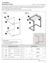
With the help of another person, place the tabletop 1 upside-down over a large
blanket to protect its top surface.
Assemble the long support bars 21 to the tabletop 1 with screws D.
STEP 1
Hardware
DM6x40 6
Pcs
ASSEMBLY STEPS
1
21
This step
requires of
2 persons
Tools (included)
21
34
14
Install the bolts A into the indicated holes on panels 3, 4, 5, 6, 7, 8, 10 and 14.
STEP 2
Hardware
AM6x35
Bolt
40
Pcs
Tools (included)
(Front)
6
78
5
34
10
(Front)
(Front)
(Front)
(Front)
(Front)
(Front)
(Front)

STEP 4
Hardware
BØ8x30 16
Pcs
Tools (NOT included)
P.8 P.8
RTA-7002
Assemble the cabinet panels 3 to the bars 21 with screws E, but DO NOT
TIGHTEN YET to allow flexibility later on when working on step 9.
STEP 3
Hardware
EM6x35 8
Pcs
21
Tools (included)
(Front)
3
3
(Front)
(Front)
Panels 3 have bolts
installed at the back
but not at the front
Insert the dowels B into the indicated holes on panels 5, 6, 7 and 8.
STEP 5
Hardware
24
2 "flat" pieces
per set:
2 "L shape"
pieces per set:
Grab the 2 sets of sliders 24 (total 8 pieces) and separate them into 2 groups
according to their shape:
The "flat" ones will be used on the next step.
The "L" shaped will be used until step 17, set them aside.
(Front)
(Front) (Front)
(Front)
24 "Flat"
RIGHT
LEFT
RIGHT
LEFT
The "flat" ones will be
used on the next step. The "L" shaped will be used
until step 17, set them aside.
24 "L" Shaped
DO NOT TIGHTEN
THE SCREWS E,
LEAVE THEM LOOSE
Panel 1 has
the big hole
at its back
578
6

(Bottom)
P.9 P.9
RTA-7002
9
Join the side panels 5 and 6 to back panel 9, insert the cam locks on panel 9
and turn them to lock the pieces as explained in page 5.
Join the side panels 7 and 8 to back panel 9, insert the cam locks on panel 9
and turn them to lock the pieces as explained in page 5.
STEP 7
Hardware
ACam lock
8
Pcs
Tools (included)
Cam locks
alignment on 9
Assemble the "Flat" sliders 24 to the side panels 5 (left) and 6 (right) with
screws J respectively (left sliders to 5, right sliders to 6).
NOTES:
The wheels go towards the front of the panels.
Attach first on the front, through the 3rd hole on the slider.
The sliders will show 2 free holes above the wheels.
STEP 6
Hardware
JM3x14 8
Pcs
Tools (included)
(Front)(Front)
24 "Flat", LEFT
24 "Flat", RIGHT
6
5
(Front)
(Front)
(Bottom)
6
(Front)
(Bottom)
7
8
5
9
(Front)
(Top)
(Front)

(Front)
P.10 P.10
RTA-7002
With the help of another person, place the panels 5-6-9 upside-down over the
panel 3 located on your RIGHT (with tabletop front facing towards you) and
assemble the pieces with cam locks A as explained in page 5.
Follow the same procedure for panels 7-8-9 to panel 3 located on your LEFT.
Please note that when the item is completely finished, the drawers will be on
the LEFT and the storage door on the RIGHT; interchanging the sections is not
possible.
STEP 8
Hardware
This step
requires of
2 persons
3
3
Cam locks
alignment on
5, 6, 7, 8 & 9
6
7
8
5
ACam lock
12
Pcs
Tools (included)
9
9
(Bottom)
(Top)
(Bottom)
(Top)
(Front)
(Front)
Insert the nuts L into the middle back panel 2 in a way that the threaded holes
run horizontally, then with the help of another person, assemble the panel to
the side panels 6 and 7 with screws C.
If the screws don't seem to catch into the threaded hole of the nuts, first make
sure the nuts are aligned to receive the screw and that the screws for panel 3
are loosen for flexibility (refer to step 3).
After installing panel 2, tighten the screws on panel 3.
STEP 9
Hardware
This step
requires of
2 persons
CM6x50
4
Pcs
Tools (included)
LM6-Ø10
4
Pcs
6
7
6
7
2
2
Threaded
hole goes
horizontally
C
L
Don't forget to tighten screws on 3

P.11 P.11
RTA-7002
Assemble the metal supports 22 to the metal "U" legs 20 with screws E as
shown. Please note that the indented holes in the middle go facing UP as they
will make the screw heads flushed for the next step.
Attach the glide studs 27 to the bottom of the legs 20.
STEP 11
Hardware
EM6x35 8
Pcs
Tools (included)
Indented holes face UP
20
22
27
STEP 10
Hardware
ACam lock
12
Pcs
Tools (included)
Assemble the bottom panels 4 to both cabinets with cam locks A as explained
in page 5.
6
78
5
9
9
(Front)
4
4
(Front)
(Front)
Cam locks
alignment on
5, 6, 7, 8 & 9

P.12 P.12
RTA-7002
19
26
H
I
Assemble the hinges 25 to the door 19 with screws I.
Assemble one of the handles 26 to the door 19 with screws H.
STEP 13
Hardware
Assemble the support 22 to the bottom panels 4 with screws F.
STEP 12
Hardware
FM6x25 8
Pcs
Tools (included)
4
4
22
HM4x22 2
Pcs
I4
Pcs
M3.5x14
Tools (included)
25

P.13 P.13
RTA-7002
STEP 14
78
This step
requires of
2 persons
Hardware
JM3x14 2
Pcs
K1
Pc
Tools (included)
With the help of another person, carefully turn the unit built in step 12 upright.
Attach the bracket (door stopper) K to the upper front corner inside the middle-
left side panel 7 with screws J.
With the help of another person, assemble the hinges 25 from the door 19 to
the right side panel 8 with screws I on the oval holes only.
Check to make sure the door closes smoothly, but if not, adjust its alignment as
shown below, and when done, secure the hinges with screws I on the round
holes.
I8
Pcs
M3.5x14
KJ
I25
ONLY ON OVAL HOLES
INSIDE TOP FRONT CORNER
To adjust the alignment of the door, loosen up
the following screws, align the door accordingly,
then re-tighten:
Loosen up to
align the height
(Up-Down)
Loosen up
to align
side-to-side
Loosen up to
align the depth
(Front-Back)
Loosen up to
align the height
(Up-Down)
After the alignment is done,
screw on round holes
I25
19

(Front)
(Bottom)
P.14 P.14
RTA-7002
For the small drawer, assemble the side panels 11 and 12 to the back panel 13
in their respective sides with screws G, then slide the bottom board 18 through
the grooves of the side panels and into the back panel.
For the big drawer, assemble the side panels 15 and 16 to the back panel 17 in
their respective sides with screws G, then slide the bottom board 18 through the
grooves of the side panels and into the back panel.
STEP 15
Hardware
GM3.5x40 8
Pcs
11
12
13
15
16
17
18
26
Tools (included)
For the small drawer, assemble the front panel 10 to the side panels 11 and 12
with cam locks A as explained in page 5.
For the big drawer, assemble the front panel 14 to the side panels 15 and 16
with cam locks A as explained in page 5.
For both drawers, attach the handles 26 to their front panels with screws H.
STEP 16
Hardware
ACam lock 8
Pcs
HM4x22 4
Pcs
Tools (included)
18
Cam locks alignment
on 11, 12, 15 & 16
10
26
14
11
12
15
16
(Front)
(Front)
(Front)
(Bottom)

(Front)
(Back)
Front
24
If you install as below,
the drawer raises 1"
and won't fit in the unit.
When finished, the sliders
look like this:
Sliders
Sliders
(Top)
(Bottom)
Back
LEFT
RIGHT
24
(Front)
(Back)
LEFT
RIGHT
24
24
P.15 P.15
RTA-7002
STEP 17
Hardware
JM3x14 8
Pcs
1
23
Tools (included)
Insert the drawers into the cabinet, the bottom drawer first, then insert the top
drawer at an angle with its front facing down.
Attach the grommet 23 into the hole of the tabletop 1.
STEP 18
For each of the drawers, flip them upside-down and assemble the L
shaped sliders 24 to the side panels on the bottom with screws J.
NOTES:
- The wheels go towards the back of the drawers.
- The sliders should not protrude on the bottom; if they do, the
drawers will raise 1" more and won't fit on the desk.

Give yourself a nice pat on the back, you did a great job!
P.16 P.16
RTA-7002
ALL DONE!
ENJOY YOUR NEW UNIT!

P.17 P.17
RTA-7002
Clean the surfaces preferable with a clean cloth damped in a solution of mild soap and water,
then dry with a clean towel.
If you decide to use a cleaning agent, test first on an area hidden from view such as
underneath the tabletop.
Every 4 months, inspect the unit completely and make sure that all screws are tighten.
When transporting the unit to places far away, protect and secure the unit to avoid damage in
transit.
Shall any part of the unit become defective during the warranty period, replacement parts
might be available to you at no charge. Please refer to the last pages on this manual.
The warranty does not extend to regular wear and tear, nor the manufacturer assumes liability
for damages or consequences due to accidents, incorrect assembly, negligence, improper
use, modifications, or not heeding the above warnings.
WEIGHT LIMITS
CARE AND MAINTENANCE
WARNINGS
Do not exceed the indicated weight limits.
Do not expose the surfaces to direct sunlight or to extreme environmental conditions.
Do not use solvents or abrasive materials to clean the unit.
Do not sit on the unit or lean against it.
Do not allow small children to play under or over the unit.
Do not allow small children to reach inside the drawers or storage without your supervision.
Do not pull, push or drag the unit to move it for more than 1 feet. The unit must be lifted by at
least 2 persons when moving in the same or adjacent rooms.
Before moving the unit, make sure to secure or remove any object that is heavy or might fall off.
Please note that lifting from the tabletop with too much weight on the product might lead to part
damage/separation.
When lifting the unit, use both hands and bend your knees, not your backs.
33 Lbs
(15 Kg)
33 Lbs
(15 Kg)
33 Lbs
(15 Kg)
110 Lbs
(50 Kg)
10 Lbs
(4.5 Kg)
15 Lbs
(6.8 Kg)

P.18 P.18
RTA-7002
TECHNI MOBILI WARRANTY
RTA Products, LLC warrants to the Original Purchaser who acquired a new product from RTA
Products or its authorized resellers that this product will be free from defects in its workmanship
and materials, under normal use and service conditions, as described herein. "Defects" as used
in this warranty, is defined as any imperfections that impair the use of the furniture or product.
RTA Products LLC will replace any defective part, at its discretion, and without charge to the
original purchaser other than the freight from the end consumer to RTA Products.
Replacement parts can only be supplied if parts are available. Items out of production may be
unavailable. This warranty will be effective for the applicable time period beginning the date of
purchase on your original sales receipt. RTA product’s obligation under this warranty is limited to
repairing or replacing products or parts as provided herein. This product has been designed for
and is intended for office and home-office use only. This warranty is Original Purchaser’s sole
remedy for product defects, and this warranty does not extend to any product, or damage to any
product, caused by or attributed to abuse or misuse, products used for commercial or rental
purposes, use modifications of, or attachments to the product, and products or parts not used,
maintained, or extended hereunder is in lieu of any and all other warranties, express or implied,
including without limitations any implied warranty or merchantability or of fitness for a particular
purpose. Please note, all desks made with PVC Laminate surface should not be exposed to
direct sunlight, as it may damage the material. Damage of this nature is not covered under this
warranty.
RTA Products will not be responsible for indirect, special, incidental or consequential damages.
This warranty is limited to merchandise purchased in the Continental United States, excludes
AK, HI and PR. Some States do not allow the exclusion or limitation of incidental or
consequential damages, so the above limitations or exclusions may not apply to you. This
warranty gives you specific legal rights. You may also have other rights that may vary from state
to state.
RTA Products will advise you of the procedure to follow in making warranty claims. The following
are the procedures for warranty claims:
a. Call us Monday – Friday, from 9am-5pm (Eastern Time) at (866) 782-5520 to explain the
defect and give your name, address and phone number. Please have ready the model number
of our product, date and place of purchase. You can also write to us by e-mail to
[email protected] and include the same information.
b. If we determine that replacement will remedy the situation, and in order to determine the
extent or the cause of the defect, purchaser will need to send the part in question at purchaser’s
expense. Once we receive the part, we will examine it and determine whether the claim is valid
(or not), and then proceed to send the replacement. We will ship the replacement at our
expense.
DESKS/LAPTOP CARTS/FILE CABINETS: LIMITED 5-YEAR WARRANTY

Your satisfaction is very important to us. Our Support agents can help
you with any issues you may have, please feel free to contact us with any
questions you have about our products, or to request replacement parts.
FOR ADDITIONAL INFORMATION
PLUS HELP OPTIONS
VISIT: WWW.TECHNIMOBILI.COM
CLICK ON SUPPORT TAB
Or scan the following QR Code:
EMAIL US:
To request replacement parts, email us with the model number
of the product, the part number or letter of the requested part,
and proof of purchase.
/