Page is loading ...

FlexLine Spa
Control
ÁFL-TSPA.ENäÈ
FL-TSPA.EN
E-8881168
Manual

Page 2
The device-specific wiring diagrams are included in the scope of delivery. Please keep
them carefully for future use.
Risk of electrical shock!
Hazardous electrical high voltage!
All electrical work to be performed by certified expert staff (electricians or expert personnel with
eqivalent training) only.
Certain computer programs contained in this product [or device] were developed by HygroMatik
GmbH ("the Work(s)").
Copyright © HygroMatik GmbH [30.08.2021]
FlexLine SPA Control
Validity: This documentation is valid for the control system of the Flexline device series.
All Rights reserved.
Current version of this manual can be found at: www.hygromatik.co.uk
HygroMatik GmbH grants the legal user of this product [or device] the right to use the Work(s)
solely within the scope of the legitimate operation of the product [or device]. No other right is
granted under this licence. In particular and without prejudice to the generality of the foregoing,
the Work(s) may not be used, sold, licensed, transferred, copied or reproduced in whole or in
part or in any manner or form other than as expressly granted here without the prior written con-
sent of HygroMatik GmbH.
Information in this manual is subject to change or alteration without prior notice.
WARNING
!

Page 3
1. Introduction ....................................................................................................................... 5
1.1 Typographic Distinctions ...................................................................................................5
1.2 Documentation .................................................................................................................. 5
1.3 Symbols in Use ................................................................................................................. 5
1.3.1 Specific Symbols related to Safety Instructions ............................................................. 5
1.3.2 General Symbols ............................................................................................................ 5
2. Safety Instructions ............................................................................................................ 7
2.1 Guidelines for Safe Operation ........................................................................................... 7
2.1.1 Scope ............................................................................................................................. 7
2.1.2 Unit control ..................................................................................................................... 7
2.1.3 Unit Operation ................................................................................................................ 7
2.1.4 Mounting, dismantling, maintenance and repair of the unit ............................................ 8
2.1.5 Electrical ......................................................................................................................... 8
2.2 Disposal after dismantling ................................................................................................8
3. Overview of the operation and layout of a steam bath .................................................. 9
3.1 Layout of steam bath (schematic diagram) ....................................................................... 10
3.2 Temperature sensor usage ............................................................................................... 11
3.2.1 Installation of the temperature sensor ............................................................................ 11
3.2.2 Connection of the temperature sensor ........................................................................... 11
3.3 Steam bath temperature control ........................................................................................ 11
3.4 Fan control ........................................................................................................................ 12
3.4.1 Supply fan ...................................................................................................................... 12
3.4.2 Exhaust fan .................................................................................................................... 12
3.5 Sample diagram for temperature profile in steam bath ..................................................... 13
4. Description of control ....................................................................................................... 14
4.1 General description ........................................................................................................... 14
4.2 Layout of control ................................................................................................................ 14
4.3 Mainboard ......................................................................................................................... 15
4.3.1 Connections on the mainboard ...................................................................................... 16
4.4 Expansion board (double cylinder units) .......................................................................... 17
4.4.1 Connections on the expansion board ............................................................................. 17
4.5 Relay circuit board ............................................................................................................. 18
4.5.1 Connections on the relay board ..................................................................................... 18
4.6 Electrical connection ......................................................................................................... 19
4.6.1 Connection of control voltage ......................................................................................... 19
4.6.2 Connection of interlock (safety) system ......................................................................... 19
4.6.3 Connection of the temperature sensor(s) ....................................................................... 20
4.6.4 Connecting the digital input (DI) ..................................................................................... 20
4.6.5 Wiring for control signal and safety (interlock) system for multiple units ........................ 20
5. The display ......................................................................................................................... 21
6. Operation of control .......................................................................................................... 23
6.1 Operation basics ............................................................................................................... 23
6.2 Screen 1 - Commissioning ................................................................................................ 25

Page 4
6.2.1 Setting the language ...................................................................................................... 25
6.2.2 Input of date and time of day .......................................................................................... 25
6.2.3 Control settings .............................................................................................................. 26
6.3 Screen 2 - Main screen .....................................................................................................27
6.3.1 Changing the set point temperature ............................................................................... 28
6.4 Password entry .................................................................................................................. 29
6.5 Screen 3 - Main menu (user level) .................................................................................... 29
6.6 User level submenus ......................................................................................................... 29
6.6.1 Settings submenu ........................................................................................................... 31
6.6.2 Reading values submenu ............................................................................................... 32
6.6.3 History submenu ............................................................................................................ 34
6.7 Screen 3 - Main menu (operator level) .............................................................................. 36
6.8 Operator level submenus .................................................................................................. 37
6.8.1 Settings submenu ........................................................................................................... 38
6.8.2 Reading values submenu .............................................................................................. 39
6.8.3 Control submenu ............................................................................................................ 39
6.8.4 Service submenu ............................................................................................................ 40
6.8.5 History submenu ............................................................................................................ 42
6.8.6 Blow-down submenu ...................................................................................................... 43
6.8.7 Fill parameters submenu ................................................................................................ 43
6.8.8 Functions submenu ........................................................................................................44
6.8.9 Communication interface submenu ................................................................................ 46
6.8.10 Weekly timer submenu ................................................................................................. 47
6.8.11 SPA submenu .............................................................................................................. 48
6.8.12 Essence submenu ........................................................................................................ 49
6.8.13 Recording submenu ..................................................................................................... 50
6.8.14 Cylinder extension submenu ........................................................................................ 52
6.8.15 Relay extension 1 submenu ......................................................................................... 53
6.8.16 Relay extension 2 submenu ......................................................................................... 54
7. Faults and service messages ........................................................................................... 58
7.1 Fault handling .................................................................................................................... 58
7.1.1 Table of fault messages, possible causes and countermea-sures ................................. 58
7.2 Servicemessages and warnings ....................................................................................... 65
7.3 Functional fault chart ......................................................................................................... 66
8. Wiring diagrams ................................................................................................................ 70
8.1 FLE - Option 230V ............................................................................................................. 70
8.2 FLE - Option 24V ............................................................................................................... 77
8.3 FLH - Option 230V ............................................................................................................ 80
8.4 FLH - Option 24V .............................................................................................................. 83
8.5 FLP - Option 230V ............................................................................................................. 86
8.6 FLP - Option 24V ............................................................................................................... 89
9. Glossary ............................................................................................................................. 92
10. Technical data ................................................................................................................. 97

Page 5
1. Introduction
Dear Customer,
Thank you for choosing a HygroMatik steam
humidifier.
HygroMatik steam humidifiers represent the
latest in humidification technology.
In order to operate your HygroMatik steam
humidifier safely, properly and efficiently,
please read these operating instructions,
which are supplemented by other operating
instructions for the relevant basic unit.
Employ your steam humidifier only in sound
condition and as directed. Consider potential
hazards and safety issues and follow all the
recommendations in these instructions.
If you have additional questions, please con-
tact your expert dealer.
For all technical questions or spare parts
orders, please be prepared to provide unit
type and serial number (see name plate on
the unit).
1.1 Typographic Distinctions
•Preceded by a bullet: general speci-
fications
» Preceded by an arrow: procedures
for servicing or maintenance which
should or must be performed in the
indicated order
Installation step which must be
checked off.
italics Terms used with graphics or
drawings
1.2 Documentation
Retention
Please retain these operating instructions in
a secure, always accessible location. If the
product is resold, turn the documentation
over to the new operator. If the documenta-
tion is lost, please contact HygroMatik.
Versions in Other Languages
These operating instructions are available in
several languages. If interested, please con-
tact HygroMatik or your HygroMatik dealer.
1.3 Symbols in Use
1.3.1 Specific Symbols related to
Safety Instructions
According to ANSI Z535.6 the following
signal words are used within this document:
DANGER indicates a hazardous situation
which, if not avoided, will result in death or
serious injury.
WARNING indicates a hazardous situation
which, if not avoided, could result in death or
serious injury.
CAUTION indicates a hazardous situation
which, if not avoided, could result in minor or
moderate injury.
NOTICE is used to address practices not
related to physical injury.
1.3.2 General Symbols
This symbol is used whenever a situation
requires special attention beyond the scope
of safety instructions.
DANGER
!
WARNING
!
CAUTION
!
NOTICE
Please note

Page 6
Intended Use
The control described is an integral part of a
HygroMatik steam humidifier. Use for other
applications is not permitted. All instructions
on intended use, which are given in connec-
tion with the basic device, apply.
Proper usage also comprises the adherence
to the conditions specified by HygroMatik for:
• installation
• dismantling
• reassembly
• commissioning
• operation
• maintenance
• disposal
Only qualified and authorised personnel may
operate the unit. Persons transporting or
working on the unit must have read and
understood the corresponding parts of the
Operation and Maintenance Instructions and
especially the chapter 2. „Safety Notes“.
Additionally, operating personnel must be
informed of any possible dangers. You
should place a copy of the Operation and
Maintenance Instructions at the unit‘s opera-
tional location (or near the unit).
By construction, HygroMatik steam humi-
difiers are not qualified for exterior appli-
cation.
Risk of scalding!
Steam with a temperature of up to 100 °C
is produced.
Do not inhalate steam directly!
WARNING
!

Page 7
2. Safety Instructions
These safety instructions are required by law.
They promote workplace safety and accident
prevention.
2.1 Guidelines for Safe Opera-
tion
2.1.1 Scope
Comply with the accident prevention regula-
tion „DGUV Regulation 3“ to prevent injury to
yourself and others. Beyond that, national
regulations apply without restrictions. This
way you can protect yourself and others from
harm.
2.1.2 Unit control
Do not perform any work which compromises
the safety of the unit. Obey all safety instruc-
tions and warnings present on the unit.
In case of a malfunction or electrical power
disruption, switch off the unit immediately and
prevent a restart. Repair malfunctions
promptly.
Restricted use.
IEC 60335-1 stipulates as follows:
This device may be used by children of eight
years of age and above as well as by persons
with reduced physical, sensory or mental ca-
pabilities or lack of experience and knowledge
so long as they are supervised or have been
instructed regarding the safe use of the de-
vice and understand the hazards that may re-
sult from it. Cleaning and user maintenance of
the unit must not be undertaken by children
without supervision.
2.1.3 Unit Operation
Risk of scalding!
Uncontrolled hot steam escape in case of
leaking or defective components possible.
Switch off unit immediately.
For Ministeam devices applies:
Risk of scalding!
No persons may be under the cloud of steam
blowing out (at a distance of approx. 1 m/40
inch in the direction of blowing out and 0.5 m/
20 inch on both sides of the device).
Risk of material damage!
• The unit may be damaged if switched
on repeatedly following a malfunction
without prior repair. Rectify defects
immediately!
• The unit must not be operated on a DC
power supply.
• The unit may only be used connected
to a steam pipe that safely transports
the steam (not valid for MiniSteam
units).
• Regularly check that all safety and
monito-ring devices are functioning
normally. Do not remove or disable
safety devices.
• Steam operation is only allowed when
the unit cover is closed.
Water leaks caused by defective connec-
tions or malfunctions are possible.
Water is constantly and automatically filled
and drained in the humidifier. Connections
and water-carrying components must be
checked regularly for correct operation.
WARNING
!
WARNING
!
WARNING
!
NOTICE
NOTICE

Page 8
2.1.4 Mounting, dismantling, mainte-
nance and repair of the unit
The HygroMatik steam humidifier is IP20 pro-
tected. Make sure that the unit is not object to
dripping water in the mounting location.
Installing a humidifier in a room without water
discharge requires safety devices to protect
against water leakages.
• Use genuine spare parts only
• After any repair work, have qualified
personnel check the safe operation of
the unit
• Attaching or installing of additional
components is permitted only with the
written consent of the manufacturer
Do not install HygroMatik steam generators
above electrical equipment such as fuse
boxes, electrical appliances, etc. In the case
of a leakage, leaking water can damage the
underlying electrical equipment
2.1.5 Electrical
Risk of electrical shock!
Hazardous electrical voltage!
Any work on the electrical system to be per-
formed by certified expert staff (electricians
or expert personnel with comparable training)
only.
Steam operation may only be started when
the unit cover is closed.
During maintenance or installation work, the
device must be disconnected from the power
supply and secured against being switched
on again. The absence of voltage must be
ensured by a measurement.
Leaks can cause leakage currents. Observe
safety regulations on working with voltage
parts (applies to electrode steam humidifi
es).
After electrical installation or repair work, test
all safety mechanisms (such as grounding
resistance).
Use only original fuses with the appropriate
amperage rating.
Regularly check the unit‘s electrical equip-
ment. Promptly repair any damage such as
loose connections or burned wiring.
Responsibility for intrinsically safe installation
of the HygroMatik steam humidifiers is
incumbent on the installing specialist com-
pany.
2.2 Disposal after dismantling
The humidifier is made up of metal parts and
plastic parts. In reference to European Union
directive 2012/19/EU issued on 4 July 2012
and the related national legislation, please
note that:
The components of the electrical and elec-
tronic devices must not be disposed of as
municipal waste, and therefore the method of
waste separation must be applied. The public
or private waste collection systems defined
by local legislation must be used.
The operator is responsible for the disposal
of unit components as required by law.
NOTICE
NOTICE
WARNING
!
NOTICE
NOTICE

Page 9
3. Overview of the operation
and layout of a steam bath
The HygroMatik steam generator provides
the steam bath with the steam required for
operation. The temperature measured in the
steam bath is the only control variable used
to control the steam production. When stan-
dard settings are used, the steam bath
reaches approx. 45 °C at 100% humidity.
One or, if required, two supply fans introduce
fresh air to the steam bath, one or two
exhaust fans extract warm air from the steam
bath to ensure a continuous supply of steam
and stable temperature control. The steam
generator can control up to 4 essence injec-
tors.
Heating-up phase:
Steam is supplied to the steam bath, which is
still cold. As a result, the relative humidity
increases first to 100%, while the tempera-
ture remains almost constant. A further sup-
ply of steam then increases the temperature;
the relative humidity remains at 100%.
Operational phase:
When the set point temperature value +
switch-off temperature difference has been
reached, steam production is interrupted. If
the steam bath temperature sinks below the
adjustable set point temperature, steam is
again introduced into the cabin.
Controls for lights, fans and essences are
optional accessories. The HygroMatik steam
bath functions are optionally available in 24 V
or 230 V versions.
There is a danger of electric shock due in
case of non-observance!
Only safety extra-low voltage (24 V) may be
used in the steam cabin for fans and lights.
Risk of scalding!
• Ensure that there is no skin contact
with the hot steam in the direct area of
steam supply to the cabin.
• Ensure that possible condensate from
the point of steam feed into the cabin
cannot drip on the skin.
Please note
WARNING
!
WARNING
!

Page 10
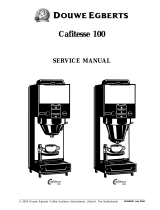
3.1 Layout of steam bath
(schematic diagram)
Position Designation
1 Steam generator
2 Essence peristaltic pump
3 Essence container
4 Essence line to steam hose
5 T-piece for essence injection into steam hose
6 Steam hose
7 Steam manifold in steam bath
8 Supply fan
9 Temperature sensor
10 Exhaust fan
11 Cabin light
The following figure shows a simplified diagram of a steam bath - it is not an installation
instruction!
Please note
9
10 11
6
1
542
3
7
8

Page 11
3.2 Temperature sensor usage
A temperature sensor must be installed in the
cabin for a steam bath. The sensor measures
the actual temperature and transmits the
measurement value to the control. The tem-
perature serves as the controlled variable for
controlling the steam production.
3.2.1 Installation of the temperature
sensor
The best mounting position of the tempera-
ture sensor is 800 to 1000 mm (31 to 39 inch)
above the seating surface (and thus in the
height of head of the persons in the steam
bath cabin). The sensor must be mounted
directly to the wall surface. Installation under
a panelling would falsify the measurement
result.
The sensor must not be mounted directly
above the steam entrance into the cabin.
Risk of scalding when steam bath tempe-
rature rises due to temperature sensor
manipulation!
Do not cover the temperature sensor or pour
over cold water.
3.2.2 Connection of the temperature
sensor
The connection cable of the temperature
sensor is to be wired to terminals 4 and 7 of
the FlexLine SPA control. The sensor has
been adjusted ex-factory. Verifying of the
measurement value can be made by using
the temperature/resistance table following
below. Readjustment of the sensor can be
made in a +/- 5 K range, if required. In this
case, an additional temperature measure-
ment device is required for referencing.
3.3 Steam bath temperature con-
trol
The steam output of the HygroMatik steam
generator is controlled by the FlexLine SPA
control according to the measured tempera-
ture. The relative humidity is not measured
because it is always 100% after the heating-
up phase. Essence injectors, lights and sup-
ply and exhaust fans, which are available as
order options, can be connected to the steam
generator.
The functioning of the temperature control is
illustrated by the sample diagram in section
3.5, which is based on the following default
values:
Steam bath temperature set value: 45 °C
ΔTemp._steam_on/off: 1K
(Temp._set value + Temp._steam_on/off) =
45 °C + 1K = 46 °C
• When 46 °C has been reached, steam
production is switched off in 1 step
operation, during continuous operation
(with the internal PI controller), it is
reduced
• If the temperature in the steam bath
drops below the set value 45 °C, steam
production is resumed (1 step opera-
tion) or ramped up (continuous opera-
tion)
Please note
WARNING
!
Temperature/resistance-table
Temperature in °C Resistance in kΩ
10 28,5
20 18,5
30 12,3
40 8,3
50 5,8
60 4,1
70 2,9
80 2,1

Page 12
3.4 Fan control
The influences of the fan control of the supply
and exhaust fans (both in automatic mode)
are also illustrated in the sample diagram.
3.4.1 Supply fan
The supply fan is switched on by the control,
as long as the steam bath temperature has
not reached the set value. It switches off at
(Temp._set value + supply fan 1_ΔTemp.) In
the example:
Temperature set value: 45 °C
Supply fan 1_ΔTemp.: 1K
• The supply fan 1 switches off at
45 °C + 1K = 46 °C
• Supply fan 1 switches back on again if
the temperature falls below the temper-
ature set value
If a second supply fan is used or if the supply
fan has a 2nd power level, both supply fans
are switched on until the temperature set
value is reached. Analogous to supply fan 1,
supply fan 2 is switched off when (Temp._set
value + supply fan 2_ΔTemp.) is reached.
This mechanism is not illustrated in the sam-
ple diagram. Numerically, it could be repre-
sented as follows:
Temperature set value: 45 °C
Supply fan 1_ΔTemp.: 2K
Supply fan 2_ΔTemp.: 0.5 K
• Supply fan 1 switches off at 45 °C + 2 K
= 47 °C
• Supply fan 2 switches off at 45°C + 0.5
K = 45.5 °C
3.4.2 Exhaust fan
The exhaust fan is switched on if the temper-
ature set value is exceeded. The exhaust fan
switches off when the temperature falls below
(Temp._set value - exhaust fan 1_ΔTemp.).
In the example:
Temperature set value: 45 °C
Exhaust fan 1_ΔTem p .: 1K
• The exhaust fan switches off at
45 °C - 1K = 44 °C
If a second exhaust fan is used or if the
exhaust fan has a 2nd power level, this addi-
tionally switches on if (set temperature value
+ exhaust fan 2_ΔTemp.) has been reached.
This mechanism is not illustrated in the sam-
ple diagram. Numerically, it could be repre-
sented as follows:
Temperature set value: 45 °C
Exhaust fan 1_ΔTe m p .: 1K
Exhaust fan 2_ΔTem p .: 0.5 K
• Exhaust fan 1 switches on at 45 °C
• Exhaust fan 2 additionally switches on
at 45.5 °C
• Both exhaust fans switch off at 44 °C
Steam is only produced as long as the tem-
perature in the steam bath is below the set
temperature. If the temperature in the steam
bath remains above the set temperature for a
long time, i.e. no visible steam is produced,
the reason for this can be:
• A high additional heat supply, e.g. due
to heated benches
• Excessive insulation of steam bath
• Insufficient ventilation in the steam bath
An exhaust fan promotes the air exchange in
the steam bath, leading to a faster tempera-
ture reduction in the steam bath. The temper-
ature drop is compensated by renewed
steam production. In this way, the fan
ensures that there is a steady, constant pro-
duction of steam and visible vapour in the
cabin a result.

Page 13
3.5 Sample diagram for tempera-
ture profile in steam bath
Temperature profile in steam bath
Temperature
46.0 °C
45.0 °C
44.0 °C
Steam production
Exhaust fan
Supply fan
Essence
Time
A = essence injection time
B = essence pause time

Page 14
4. Description of control
4.1 General description
The control is integrated into the steam
humidifier and is operated via a 3.5" graphic
display on the front of the unit.
An additional operating element on the front
of the unit is a control switch, whose posi-
tions are assigned as follows:
Pos. "0": The unit is switched off
Pos. "I": The unit is switched on
Pos. "II": The cylinder water is pumped off
without the participation of the control. The
control is not active, the display remains
dark.
By changing the parameters, the user/opera-
tor can adapt the control to the system speci-
fications and the special characteristics
relating to the use of the unit.
The operation of the unit is described in Sec-
tion 6.
4.2 Layout of control
The control consists of the 3.5" screen and
the mainboard. The mainboard can be
extended for additional functions with one or
2 relay boards (with 3 relays each) and addi-
tional optional relays in DIN rail format.
The relay boards are connected to the main-
board via a plug system.
The DIN rail relays are connected via cables
with plug. 2 additional relay modules can be
used, with 2 relays each.
For use with double cylinder units, an exten-
sion board is added to the mainboard.
The fuse protection of the control voltage for
all boards with 2 x 2.5 A Flink (F1, F2) takes
place on the mainboard.
The external circuitry for the control voltage
and the interlock (safety) system are con-
nected directly to the mainboard on plug ST1.
If additional boards are connected, the con-
nection moves from the mainboard to the out-
ermost board (see sketch).
For device versions with separate control
voltage, this is connected to clamps L and
N. For versions with internal control volt-
age and control voltage transformer, the
wiring is pre-installed here.
Control switch
ST1
N
L12
Relay
board
Main
board
ST1.1
ST1.2
ST1
Connections:
L, N: 230 VAC control voltage
1,2: Interlock (safety) system
ST1.1
non-floating 230VAC
Please note

Page 15
4.3 Mainboard
The mainboard is "the heart" of the control.
All logic functions and control operations for
the steam humidifier take place here.
The relays for the control of the main contac-
tor, solenoid valve and blow-down pump are
arranged directly on the mainboard.
Ex-factory relay assignment:
In case of a unit without any additional
options built in, assignment of the base relay
(ST03) is „Collective fault“ (0). All other relay
contacs carry the assigment „Not in use“
(284).
F1
F2 ST06 ST05 ST04-A ST04-B ST07
ST08ST03
ST1
ST09
ST10.1
ST10.2
ST13
ST12.1
USB
ST15
Main relay
Plugs for
relay 1-4
connection
(order opton)
ST11.1
CAN TERM
OFF
ON
CAN TERM
OFF
ON
*)
*) This jumper must always be set to „ON“

Page 16
4.3.1 Connections on the mainboard
The use of the connections is illustrated by
the wiring diagrams (see Chapter 8)
4.3.1.1 Customer-side computer
interfaces
Inputs
ST08:
• Input for control signal of temperature
sensor
• Configurable digital input 12 VDC
Outputs
ST03:
• Potential free break/make contacts NC
and NO, programmable, relay assigned
to "Collective fault" in factory setting
ST10.1/ST10.2:
• Connection options for optional relay
each in top-hat rail version with wiring
harness (order option)
ST07:
Control output 0...10 VDC (max. 8 mA)
ST08:
• +20 VDC supply voltage (max. 20 mA)
for humidity sensors (can be used as
auxiliary voltage for digital input)
ST15:
• Tap for 1,2 and N (max. 2.5 A) for cus-
tomer use
USB:
Connection for USB stick for use as a data
logger and for parameter or software updates
4.3.1.2 System-side interfaces
ST1:
• 4-pin screw / plug connection for the
connection of L1 and N and the inter-
lock (safety) system
ST11.1:
• +12 V, GND, CANbus
Inputs
ST09:
• Input for current transformer for ELDB
(= Electrode steam humidifier) / level
control for HKDB (heater steam humidi-
fier) with automatic detection (for expla-
nation of terms see Glossary, Index 7)
ST04-B:
• Galvanically isolated input (optical cou-
pler) for sensor electrode for ELDB
Outputs
ST04-A:
• Main contactor
ST05:
• Blow-down pump
ST06:
• Inlet solenoid valve
Bi-directional
ST12.1:
• Serial interface for screen connection
ST 13:
• Base for adapter board with RS485
interface

Page 17
4.4 Expansion board (double
cylinder units)
4.4.1 Connections on the expansion
board
4.4.1.1 Customer-side computer
interfaces
Inputs/outputs
ST05: not used
4.4.1.2 System-side interfaces
ST1.1:
• 4-pin screw / plug connection for the
connection of L1 and N and the inter-
lock (safety) system
ST1.2:
• Loop-through of ST1.1
ST07:
• +12 V, GND, CAN-Bus
ST08:
• Loop-through of ST07
Inputs
ST02-B
• Electrically isolated input (optical coup-
ler) for sensor electrode (ELDB)
• Thermoswitch connection (HKDB)
ST06:
• Input for current transformer (ELDB) /
level control (HKDB) with automatic
detection
Outputs
ST02-A:
• Main contactor
ST03:
• Blow-down pump
ST04:
• Inlet solenoid valve
ST1.1
ST07
ST08
ST1.2
ST06
ST04 ST03 ST02-A ST02-B
ST05
DIPswiches
On
12
Off
Off
*)
OFF
CAN TERM
ON
CAN TERM
OFF
ON
CAN bus termination
*)The DIP switches
serve for CAN bus adress setting. They are factory preset according to the unit configuration.
**) The jumper for the CAN bus termination is in the „ON“ position only on the lowest extension or relay board of the
assembly, i.e. the termination is then effective. On the boards that are attached in higher mounting positions, the correct

Page 18
4.5 Relay circuit board
The relay board has three additional relays
with potential free break/make contacts (con-
tact load 250 VAC/8 A) for switching or con-
trolling of additional functional units or
options.
4.5.1 Connections on the relay board
4.5.1.1 Customer-side interfaces
Inputs
ST05:
• Configurable digital input 12 VDC
Outputs
ST02:
• Potential free break/make contacts NC
and NO, programmable
ST03:
• Potential free break/make contacts NC
and NO, programmable
ST04:
• Potential free break/make contacts NC
and NO, programmable
A maximum of 2 relay boards can be
installed. When 2 boards are in use, different
CAN bus addresses must be set (see fig.
below).
4.5.1.2 System-side interfaces
ST1.1:
• 4-pin screw / plug connection for the
connection of L1 and N and the inter-
lock (safety) system
ST1.2:
• Loop-through of ST1.1
ST08:
• +12 V, GND, CAN bus
ST07:
• Loop-through of ST08
ST04 ST03 ST02
ST1.1
ST07
ST1.2
ST08
ST05
DIPswitches
On
12
On
12
Relais-Platine 1
Relais-Platine 2
Off
Off
Off
On
*)
*)
CAN TERM
OFF
CAN TERM
OFF
ON
CAN bus termination
ON
*)The DIP switches serve for CAN bus adress setting. They are factory preset according to the unit configuration.
**) The jumper for the CAN bus termination is in the „ON“ position only on the lowest extension or relay board of the
assembly, i.e. the termination is then effective. On the boards that are attached in higher mounting positions, the correct
jumper setting is „OFF“. On the main board the correct setting of the Can-Bus termination is always "ON".

Page 19
4.6 Electrical connection
Danger of electric shock!
Dangerous electric voltage!
All work relating to the electrical installation
may only be carried out by designated spe-
cialist personnel (electrician or qualified per-
son with equivalent training).
The customer / operator is responsible for
monitoring the qualifications of the specialist
personnel.
Potential component damage due to elec-
trostatic discharge!
To protect the sensitive electronic compo-
nents, measures to prevent damage due to
electrostatic discharge must be taken before
the start of the installation work.
4.6.1 Connection of control voltage
The control voltage of 230 VAC is to be
applied to the board which is closet to the
cable gland on the underside of the housing.
The plug designation differs depending on
the level of expansion:
The pin assignment is identical for all plugs. L
and N are labelled on the boards. The pins
are accessable via a terminal strip adaptor
pushed on the corresponding plug.
For device versions with internal control
voltage, no voltage must be applied to L
and N. The wiring is pre-installed here.
4.6.2 Connection of interlock (safety)
system
Danger of electric shock!
Dangerous electric voltage!
After the commisioning of the unit, a 230VAC
voltage is present at terminal 1 when stan-
dard wiring is used.
The so-called interlock (safety) system is
located between terminals 1 and 2 with termi-
nal 1 holding 230 VAC. For closing the inter-
lock, a make contact is required across
terminals 1 and 2. This contact is supplied by
relay K21. For energising the relay, a make
contact or a bridge is required across the
additional terminals on the hat-top rail.
If the interlock (safety) system is open, the
humidifier does not start or the operation is
interrupted.
If steam operation is interrupted for a longer
period of time, it is recommended to switch
off the steam generator or to open the safety
chain. The latter makes it possible to control
external consumers, e.g. an exhaust fan
during the fan run-on time to dry out the
steam bath, although steam operation is
interrupted.
We recommend the use of safety systems
(e.g. a door contact switch).
Type of board Plug designation
Mainboard ST1
Extension board ST1.1
Relay board ST1.1
WARNING
!
Please note
NOTICE
WARNING
!
21L
N
Terminal strip on
ST1or ST1.1
Terminals 1/2 on the mainboard (terminal strip on
ST1) or on the extension/relay board (terminal strip
on ST1.1) for the connection of the interlock (safe-
ty) system
Interlock (safety) system
NOTICE

Page 20
The interlock (safety) system is not closed
when delivered ex-factory!
The contacts, which are connected to termi-
nals 1 and 2 must be potential free and suit-
able for switching of 230 VAC.
4.6.3 Connection of the temperature
sensor(s)
If a 2nd temperature sensor is used, this is to
be connected to the extension board or to
relay board 1 (if several relay boards are
present):
4.6.4 Connecting the digital input (DI)
The digital input on the mainboard can be
used for switching functions.
The digital input must be wired on-site in
accordance with its use, e.g. with a push-but-
ton or a switch (also see chapter 6.8.8 „Func-
tion parameters“ / „Function_digital_ input“).
Wiring the digital input (DI):
4.6.5 Wiring for control signal and
safety (interlock) system for
multiple units
In the case of multiple units, separate humid-
ifiers work together. The control signal and
the safety (interlock) system are connected
to the master unit as described above. In
addition, connecting cables are established
between the guiding unit and the successing
unit(s) (provided on-site). These provide the
successing unit with a control signal from the
guiding unit and the transmitted (potential
free) safety (interlock) system.
The wiring for the control signal and the
safety (interlock) system must be imple-
mented as follows for multiple units:
1) „ST0x“ designates connector plugs on the mainboard
2) „K20“ is the relay used for the connection of the suc-
cessing unit with the installed option (CN-07-10012) or
the enclosed option (CN-07-10002)
Please note
34567
Temperature sensor 1 Terminal strip
on ST08
Connection of temperature sensor 1
to the mainboard
8
34567
Temperature sensor 2 Terminal strip
on ST05
Connection of temperature sensor 2
to extension board or
relay board 1 (if an
extension board is not present)
8
3456
7
8
3456
7
8
20VDC 20VDC
v
Terminal strip ST08/ST05
push button switch
Terminals 3/8 provided for connecting the digital
input
- mainboard (terminal strip ST08)
- extension board/relay board (terminal strip ST05
12 13 11 14
5412
ST07 K20
ST08 ST01
Guiding unit
Successing unit
1)
1) 1)
2)
/