77-2967-R2 (1/2018) 1 / 10 www.carlisleft.com
AX140S AIR MOTOR ASSEMBLY
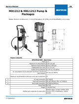
SPECIFICATIONS
AX140S-5 AX140S-6 AX140S-7 AX140S
Maximum air inlet pressure: 72.5 psi [5 bar] 87 psi [6 bar] 101.5 psi [7 bar] 116 psi [8 bar]
Maximum recommended continuous cycle rate: 20 cycles/min. [40 strokes]
Maximum recommended intermittent cycle rate: 40 cycles/min. [60 strokes]
Air consumption @ 20 cycles/min and 116 psi [8 bar]
air inlet pressure: n/a n/a n/a 17.6 SCFM
[498 LPM]
Sound level: n/a n/a n/a 97 dB
Air inlet connection: 3/8" NPS / BSPP (female)
Piston diameter: 5.5 in (140 mm)
Nominal motor stroke: 3 in [75 mm]
Maximum operating temperature: 160°F [71° C]
Weight: 13 lbs [6 Kg]
EN
SERVICE MANUAL

77-2967-R2 (1/2018)2 / 10
EN
www.carlisleft.com
Binks reserves the right to modify equipment specification without prior notice.
DE-ENERGIZE, DEPRESSURIZE, DISCONNECT AND LOCK
OUT ALL POWER SOURCES DURING MAINTENANCE
Failure to De-energize, disconnect and lock out all power supplies
before performing equipment maintenance could cause serious
injury or death.
OPERATOR TRAINING
All personnel must be trained before operating finishing
equipment.
EQUIPMENT MISUSE HAZARD
Equipment misuse can cause the equipment to rupture,
malfunction, or start unexpectedly and result in serious injury.
PROJECTILE HAZARD
You may be injured by venting liquids or gases that are released
under pressure, or flying debris.
PINCH POINT HAZARD
Moving parts can crush and cut. Pinch points are basically any
areas where there are moving parts.
INSPECT THE EQUIPMENT DAILY
Inspect the equipment for worn or broken parts on a daily basis.
Do not operate the equipment if you are uncertain about its
condition.
In this part sheet, the words WARNING, CAUTION and NOTE are used to
emphasize important safety information as follows:
Hazards or unsafe practices which
could result in minor personal injury,
product or property damage.
!
CAUTION
Hazards or unsafe practices which
could result in severe personal
injury, death or substantial property
damage.
!
WARNING
Important installation, operation or
maintenance information.
NOTE
Read the following warnings before using this equipment.
READ THE MANUAL
Before operating finishing equipment, read and understand all
safety, operation and maintenance information provided in the
operation manual.
WEAR SAFETY GLASSES
Failure to wear safety glasses with side shields could result in
serious eye injury or blindness.
NEVER MODIFY THE EQUIPMENT
Do not modify the equipment unless the manufacturer provides
written approval.
IT IS THE RESPONSIBILITY OF THE EMPLOYER TO PROVIDE THIS INFORMATION TO THE OPERATOR OF THE EQUIPMENT.
FOR FURTHER SAFETY INFORMATION REGARDING THIS EQUIPMENT, SEE THE GENERAL EQUIPMENT SAFETY BOOKLET (77-5300).
KNOW WHERE AND HOW TO SHUT OFF THE EQUIPMENT
IN CASE OF AN EMERGENCY
HIGH PRESSURE CONSIDERATION
High pressure can cause serious injury. Relieve all pressure before
servicing. Spray from the spray gun, hose leaks, or ruptured
components can inject fluid into your body and cause extremely
serious injury.
NOISE HAZARD
You may be injured by loud noise. Hearing protection may be
required when using this equipment.
STATIC CHARGE
Fluid may develop a static charge that must be dissipated through
proper grounding of the equipment, objects to be sprayed and all
other electrically conductive objects in the dispensing area. Improper
grounding or sparks can cause a hazardous condition and result in
fire, explosion or electric shock and other serious injury.
PROP 65 WARNING
WARNING: This product contains chemicals known to the
State of California to cause cancer and birth defects or other
reproductive harm.
KEEP EQUIPMENT GUARDS IN PLACE
Do not operate the equipment if the safety devices have been
removed.
!
WARNING
PACEMAKER WARNING
You are in the presence of magnetic fields which may interfere
with the operation of certain pacemakers.
PRESSURE RELIEF PROCEDURE
Always follow the pressure relief procedure in the equipment
instruction manual.
AUTOMATIC EQUIPMENT
Automatic equipment may start suddenly without warning.

77-2967-R2 (1/2018) 3 / 10
EN
www.carlisleft.com
MAINTENANCE
INSPECTION OPERATION
Daily Check for general air leakage and correct motor operation.
6 Month Test
Perform a pump stall test to ensure correct operation.
Perform a stall test on the pump assembly. If air is escaping through exhaust, check air motor
piston seal and QEV piston, replace as required.
12 to 36 Months
(Typically 10 million pump
cycles, dependant on air
quality)
Replace air piston seal.
Replace motor rod cartridge assembly.
Replace poppet assemblies.
Order a 0115-010302 Seal kit.
Inspect and replace if required:
Main valve assembly parts Order a 0115-010226 Valve repair kit.
TROUBLESHOOTING
SYMPTOM POSSIBLE CAUSE REMEDY
Motor will not run
No air supply. Check air and uid supply ball valves and supply hoses.
Air piston seal worn. Replace piston seal.
Poppet assemblies are not working. Switch/interchange poppet assemblies to isolate the faulty
poppet, and clean or replace.
Main valve assembly is not working. Check the main valve assembly, and clean or replace.
QEV's are not working. Check for constant exhaust air when pump is not in a stalled
condition. Check the QEV pistons, and clean or replace.
Pump runs but has
excessive pulsation
Worn piston seal. Replace piston seal.
Worn/failed motor rod seals. Replace motor rod cartridge assembly.
Damaged QEV. Inspect, clean and replace as required.
Damaged poppet assembly. Inspect, clean and replace as required.
Air exhaust restricted Inspect, clean and replace as required.
65
8
"
168mm
615
16
"
176mm
915
32
"
240mm
Air Inlet
3/8"
3x
1
2
"
13mm
611
16
"
170mm
Hole Circle

77-2967-R2 (1/2018)4 / 10
EN
www.carlisleft.com
29
18
10
15
19
20
22
11
13
17
12
13 14
15 16
23
24
27
28
19
15
17
16 15
7
6
5
4
3
1 8
21
21
14
9
2
25
25
26
24
30
▲ Items available separately or as a complete assembly: 0115-010660.
• Parts are included in 0115-010301 Air Motor Repair Kit.
+ Parts are included in 0115-010226 Air Motor Valve Repair Kit.
L
Parts are included in 0115-010302 Air Motor Seal Kit.
N
Parts are included in 0115-010300 AX140 Hardware Kit.
AX140S AIR MOTOR ASSEMBLY

77-2967-R2 (1/2018) 5 / 10
EN
www.carlisleft.com
AX140S AIR MOTOR ASSEMBLY
ITEM
NO. PART NUMBER DESCRIPTION QTY.
1 0115-010023 ▲EXHAUST COVER SCREEN 1
2 0115-010024 ▲ N FLAT HEAD COUNTER SUNK CAP SCREW 4
3 0115-010022 ▲EXHAUST COVER 1
4 0115-010073 ▲ N BUTTON HEAD CAP SCREW 8
5 0115-010019 ▲QUICK EXHAUST VALVE CAGE 2
6 0115-010021 ▲•+◊O-RING 2
7 0115-010020 ▲•+ DIAPHRAGM 2
8 0115-010026 ▲ NBUTTON HEAD CAP SCREW 4
9 0115-010097 ▲VALVE BLOCK 1
10 0115-010107 ▲ NPIPE PLUG 1
11
0114-014774 ▲SAFETY VALVE (8 BAR) AX140S
1
193539 ▲SAFETY VALVE (7 BAR) AX140S-7
193538 ▲SAFETY VALVE (6 BAR) AX140S-6
0114-014716 ▲SAFETY VALVE (5 BAR) AX140S-5
12 0115-010015 ▲ +SPOOL AND SLEEVE ASSEMBLY 1
13 0115-010016 ▲•+ BUMPER 2
14 0115-010017 ▲ +MAGNET 2
15 0115-010049 ▲•+◊O-RING 4
16 0115-010018 ▲ +VALVE BLOCK END CAP 2
17 0115-010051 •+◊O-RING 4
18 0115-010117 UPPER END CAP MACHINING 1
19 0115-010037 • POPPET ASSEMBLY 2
20 0115-010124 NSOCKET HEAD CAP SCREW 4
21 0115-010133 •◊O-RING 2
22 0115-010116 AX140 CYLINDER 1
23 0115-010127 NLOCKNUT 1
24 0115-010131 WASHER 2
25 0115-010132 •◊O-RING 2
26 0115-010128 AX140 PISTON 1
27 0115-010129 •◊O-RING 1
28 0115-010130 AX140 MOTOR ROD 1
29 0115-010119 LOWER END CAP MACHINING 2
30 0115-010658 • AX140 MOTOR ROD CARTRIDGE ASSEMBLY 1
▲ Items available separately or as a complete assembly: 0115-010660.
• Parts are included in 0115-010301 Air Motor Repair Kit.
+ Parts are included in 0115-010226 Air Motor Valve Repair Kit.
L
Parts are included in 0115-010302 Air Motor Seal Kit.
N
Parts are included in 0115-010300 AX140 Hardware Kit.
See page 6 for kit details.
NOTE

77-2967-R2 (1/2018)6 / 10
EN
www.carlisleft.com
AX140S SERVICE KITS
0115-010226 0115-010300 0115-010301 0115-010302
ITEM
NO. PART NO. DESCRIPTION VALVE
REPAIR KIT HARDWARE
KIT REPAIR KIT SEAL KIT
2 0115-010024 FLAT HEAD COUNTER SUNK
CAP SCREW 4
4 0115-010073 BUTTON HEAD CAP SCREW 8
6 0115-010021 O-RING 2 2 2
7 0115-010020 DIAPHRAGM 2 2
8 0115-010026 BUTTON HEAD CAP SCREW 4
10 0115-010107 PIPE PLUG 1
12 0115-010015 SPOOL AND SLEEVE ASSEMBLY 1
13 0115-010016 BUMPER 2 2
14 0115-010017 MAGNET 2
15 0115-010049 O-RING 4 4 4
16 0115-010018 VALVE BLOCK END CAP 2
17 0115-010051 O-RING 4 4 4
19 0115-010037 POPPET ASSEMBLY 2
20 0115-010124 SOCKET HEAD CAP SCREW 4
21 0115-010133 O-RING 2 2
23 0115-010127 LOCKNUT 1
25 0115-010132 O-RING 2 2
27 0115-010129 O-RING 1 1
30 0115-010658 MOTOR ROD CARTRIDGE ASSEMBLY 1
0115-010120 MOTOR ROD CARTRIDGE ASSEMBLY 1
0115-010114 SOCKET HEAD CAP SCREW 3

77-2967-R2 (1/2018) 7 / 10
EN
www.carlisleft.com
8
15
4mm
PG
4x
17
1
PG PG
17
2.5mm
2.5mm
4x
8x
1 2
3 4 56 7
PG
2
3
AX140S AIR MOTOR ASSEMBLY – MAINTENANCE
MAINTENANCE SYMBOLS
ITEM NUMBER
MAINTENANCE ORDER
(Reverse order for assembly)
PETROLEUM JELLY/GREASE
THREAD SEALANT
(PTFE tape)

77-2967-R2 (1/2018)8 / 10
EN
www.carlisleft.com
4
PG
18
21
22
30
19
29
21
20
19
PG
PG
5
6mm
9mm
4x
75 in-lb
[8.5 Nm]
Max
PG
PG
PG
5
60 in-lbs.
[6.8 Nm]
Max
6
60 in-lbs.
[6.8 Nm]
Max
AX140S AIR MOTOR ASSEMBLY – MAINTENANCE
MAINTENANCE SYMBOLS
ITEM NUMBER
MAINTENANCE ORDER
(Reverse order for assembly)
PETROLEUM JELLY/GREASE
THREAD SEALANT
(PTFE tape)

77-2967-R2 (1/2018) 9 / 10
EN
www.carlisleft.com
23
24
26
27
28
PG
21mm
16mm
7
110 - 120 in-lb
[12.4 - 13.6 Nm]
25
25
24
PG
PG
1/2in Drive
5mm
16 15 14 13
12
13
14
15
16
PG
PG
TS
10
8
9
9
DANGER
You are in the
presence of magnetic
fields which may
interfere with the
operation of certain
pacemakers.
MAINTENANCE SYMBOLS
ITEM NUMBER
MAINTENANCE ORDER
(Reverse order for assembly)
PETROLEUM JELLY/GREASE
THREAD SEALANT
(PTFE tape)
NOTE
Spool and sleeve assembly (12) is a matched
set and cannot be interchanged with other
spool and sleeve assemblies.
CAUTION
Take care when handling the magnets (14).
Avoid getting magnets in close proximity to
each other. Injury or damage to magnets
may result.
!
AX140S AIR MOTOR ASSEMBLY – MAINTENANCE

77-2967-R2 (1/2018)10 / 10
EN
www.carlisleft.com
WARRANTY POLICY
Binks products are covered by Carlisle Fluid Technologies one year materials and workmanship
limited warranty. The use of any parts or accessories, from a source other than
Carlisle Fluid Technologies, will void all warranties. For specic warranty information please contact
the closest Carlisle Fluid Technologies location listed below.
Binks is part of Carlisle Fluid Technologies, a global leader in innovative nishing technologies.
For technical assistance or to locate an authorized distributor, contact one of our international sales
and customer support locations.
USA/Canada
Tel: 1-888-992-4657
Fax: 1-888-246-5732
United Kingdom
Tel: +44 (0)1202 571 111
Fax: +44 (0)1202 573 488
China
Tel: +8621-3373 0108
Fax: +8621-3373 0308
Mexico
Tel: +52 55 5321 2300
Fax: +52 55 5310 4790
Japan
Tel: +81 45 785 6421
Fax: +81 45 785 6517
Germany
Tel: +49 (0) 6074 403 1
Fax: +49 (0) 6074 403 281
Australia
Tel: +61 (0) 2 8525 7555
Fax: +61 (0) 2 8525 7575
Carlisle Fluid Technologies reserves the right to modify equipment specications without prior notice.
DeVilbiss®, Ransburg®, ms®, BGK®, and Binks® are registered trademarks of Carlisle Fluid Technologies, Inc.
©2018 Carlisle Fluid Technologies, Inc.
All rights reserved.
For the latest information about our products, visit www.carlisleft.com.
/


