Contractors Wardrobe SIL-6081SG2X Operating instructions

Type
Operating instructions
Installation Instructions
®
Mod e l C o n c o rd
and Silhouette
DESIGNERS • MANUFACTURERS
26121 Avenue Hall • Valencia, CA 91355
TOLL FREE: (800) CW-DOORS ((800) 293-6677)
(661) 257-1177 • FAX: (661) 257-4907
or visit our website at: www.cwdoor.com
Concord/Silhouette Instructions 8/1/06 10:47 AM Page 1
Concord
/ Silhouette
- I3045 - 0806
NO. QTY PART # PART DESCRIPTION
#10 4 N1030 5 Penny Nail
#11 4 A4810 Side Mold
#12 4 A3800 Top and Bottom Mold
#13 4 W8020 Steel Wheel Assembly
#14 16 S0084 #6 x 3/8 Hex Head Screw
#15 2 G2120 Glazing Vinyl
Steel Wheel
Assembly (#13)
2
8
15
14
7
15
15
15
7
7
7
12
11
11
11
14
14
14
14
14
5
5
5
5
8
6
6
6
14
14
14
14
13
13
13
13
12
12
12
3
9,10
4
2
1
9,10
9,10
9,10
1
NO. QTY PART # PART DESCRIPTION
#1 2 Mirrored Glass Panels
#2 1 A1012 Ultraglide
®
Top Channel
F2020 with Felt Liner
#3 1 A2020 Bottom Track
#4 1 W0101 Wood Strip
#5 4 B3000 Top Guide Bracket
#6 4 S0095 #8 x 1-1/2 PH SMS Screw
#7 6 S0060 #8 x 1/2 Truss Screw
#8 4 B0101 Clear Plastic Bumper
#9 2 N2030 Concrete Nail
Silhouette Series has different parts,
see Supplemental Sheet Page 6.
A
ILLUSTRATED PARTS BREAKDOWN (IPB)
MODEL Concord
/ Silhouette
Top Guide Bracket (#5)
(Enlarged View)
A
A
A
A
A
A
A
A
A
Concord/Silhouette Instructions 8/1/06 10:48 AM Page 2
Congratulations on purchasing your new CW
®
Wardrobe
Doors. Now that you have opened the package, we want
you to verify that you have all the necessary hardware
supplied with your doors.
PARTS CHECK LIST:
NO. QTY DESCRIPTION
(#1) 2 Mirrored Glass Panels
(#2) 1 Ultraglide
®
Top Channel with Felt Liner
(#3) 1 Bottom Track
(#4) 1 Wood Strip (located inside of track)
(#6) 6 #8 x 1-1/2 PH SMS Screws:
(#7) 4 #8 x 1/2 Truss Screws:
(#8) 2 Clear Plastic Bumpers:
(#9) 4 Concrete Nails:
(#10) 4 5 Penny Nails:
If you find that any parts are damaged or missing, refer to
the Parts Check List and IPB Drawing and contact
Contractors Wardrobe
®
s Customer Service Department at
661-257-1177.
TOOL CHECK LIST:
You will need:
1. Phillips Screwdriver
2. Tape Measure
3. Hammer
4. Pencil
5. 3/8 Drill Motor and 3/16 and 1/8 Drill Bits
6. Miter Box and Hacksaw
7. Square
8. Glass Cutter for optional Mirror Fascia
9. Four 1 Screws and Screw Anchors
(For ceramic tile floors only. See Floor Check List #5.)
10. Adhesive (For ceramic tile floors only. See Floor Check
List #5.)
FLOOR CHECK LIST
1. Do you have carpet?
It is highly recommended that if you have carpet and do
not have a cut-out in the carpet already, you should cut
the carpet in order to install the Bottom Track (#3). We
do not recommend installing the Bottom Track (#3)
directly on top of carpet.
2. Do you have a concrete, wood floor or
ceramic tile floor?
A. If it is a concrete floor, go to 3
B. If it is a wood floor, go to 4
C. If it is a ceramic tile floor, go to 5
3. If you have a concrete floor you will: Use Concrete
Nails (#9) to attach Wood Strip (#4) to floor.
4. If you have a wood floor you will: Use 5 Penny N a i l s
(#10) to attach Wood Strip (#4) to wood floor.
5. If you have a ceramic tile floor you will: Drill holes
with a 3/16Masonry Drill Bit. Insert Screw Anchors and
attach Wood Strip (#4) to floor with Screws. Or, you
may glue the Wood Strip (#4) down with Panel
Adhesive.
NOTE: Drill Bit, Screws, Screw Anchors and Adhesive
are not supplied.
TRACK OFFSET MEASUREMENTS FROM FACE
OF OPENING TO FRONT EDGE OF TRACK
Track Offset A B
All Ultraglide
®
Track and Channel
Concord
/ Silhouette
doors 1/2 1-1/2
For Optional Mirror Fascia, add 1/4 to the Bottom Track
offset measurement.
Concord
/ Silhouette
- I3045 - 0806
3
PENCIL MARK TO
LOCATE FRONT
EDGE OF WOOD
STRIP
BOTTOM
TRACK
WOOD
STRIP
FACE OF
OPENING
Silhouette Series has different parts,
see Supplemental Sheet Page 6.
A
A
Concord/Silhouette Instructions 8/1/06 10:48 AM Page 3
INSTALLING THE DOORS
* Before you get started if you purchased our Silhouette
model it is almost the same as our Concord
model. Any
differences are noted with a Silhouette
Flag . If you
see this flag during an installation step please turn to
Supplemental Page 6 for that installation section.
Step 1 Removing Existing Wardrobe
Doors
Remove existing doors, brackets, top channel
and bottom track.
Step 2 Installing the Top Channel
A. Measure the opening at the top of the closet from
wall to wall.
B. Cut the new Ultraglide
®
Top Channel (#2) to this
dimension. When cutting the Top Channel (#2) we
r e c o m m e n d that you use a Miter Box and
Hacksaw for a straight cut. Cut one side only.
NOTE: If your closet has bumper jambs you may need to
notch your Top Channel (#2) on each end.
C. When cut to proper length, install Top Channel
(#2) up to the top front of closet opening making
sure that the front of the Top Channel (#2) is flush
with outside walls (See Figure 1). Hold up the Top
Channel (#2) in the desired position and with
your Pencil, mark where the pre-drilled holes are
in the Top Channel (#2).
Figure 1
D. Remove the Top Channel (#2) and drill holes
using 1/8Drill Bit where you made the pencil
marks. Now install the Top Channel (#2) in place
using six #8 x 1-1/2PH SMS Screws (#6).
Step 3 Installing the Bottom Track
A. Make sure that you have used the FLOOR
CHECK LIST on Page 3 to determine which floor
and installation you will use.
NOTE: If the floor board molding continues into the
c l o s e t opening, you may need to remove it so that
the Wardrobe Doors will close flush to the wall.
B. Locate Wood Strip (#4) supplied in kit and
measure inside bottom closet opening and cut to
length.
C. Find the correct offset measurement using the
O ffset Measuring Ta b l e on Page 3 (B
Measurement) for your particular installation. From
the front edge of closet opening inward, measure
using dimension from table and make a pencil
mark on wall. Do this on both walls, i.e., right and
left walls (See Figure 2).
Figure 2
D. Place front of Wood Strip (#4) up to pencil mark
on wall (See Figure 3). Do this on both sides. Now
attach Wood Strip (#4) according to your Offset
Measuring Table.
E. Cut the Bottom Track (#3) to your measurement of
the inside closet opening. Slide the Bottom Tr a c k
(#3) over Wood Strip (#4) and attach with four
#8 x 1/2Tr u s s Screws (#7).
Figure 3
Concord
/ Silhouette
- I3045 - 0806
PENCIL MARK
TO LOCATE
FRONTEDGE
OF WOOD
STRIP
PENCIL MARK
TO LOCATE
FRONT EDGE
OF WOOD
STRIP
4
ALIGN TOP CHANNEL
FLUSH WITH THE WALL
S
Concord/Silhouette Instructions 8/1/06 10:48 AM Page 4
Thank you for purchasing a CW
®
Wardrobe Door.
This is only one of a large line of wardrobe doors and
high quality bath enclosure products. If you like this
product, please contact Contractors Wardrobe
®
for
more information about our many beautiful bath
enclosures available in a vast array of colors and
finishes to suit your designing needs.
Step 4 Installing the Mirrored
Glass Panels (Concord
only)
A. Make sure you have a pad or
blanket to protect the Mirrored
Glass Panels ( # 1 ) f r o m
scratches. Lay Mirrored Glass
Panels ( # 1 ) with backside up on
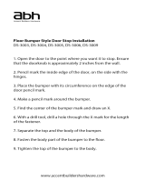
the floor. Locate one of the Steel
Wheel Assemblies (#13) on the
b o t t o m of a Mirrored Glass Panel
( # 1 ). With a Phillips
S c r e w d r i v e r, turn the a d j u s t i n g
screw to the right to lower the
r o l l e r. Do this until you have 1 o f
roller showing. Adjust both Wheel A s s e m b l i e s (#13)
on each Mirrored Glass Panel ( # 1 ) (This will
avoid scratching the Bottom Track (#3) when
installing the panels).
B. Pick up one Mirrored Glass Panel ( # 1 ) and, with
the mirror facing you, tilt the top of the Mirrored
Glass Panel ( # 1 ) back and slip the Mirrored Glass
Panel ( # 1 ) into the back runner of the To p
Channel (#2). Next, set the bottom of the Mirrored
Glass Panel (#1) into the back runner of the
Bottom Track (#3).
C . For the front Mirrored Glass Panel ( # 1 ), repeat B,
but place the Mirrored Glass Panel ( # 1 ) into the
front runner of the Top Channel (#2) and front
runner of the Bottom Track (#3).
Step 5 Adjusting the Panels
(Concord
only)
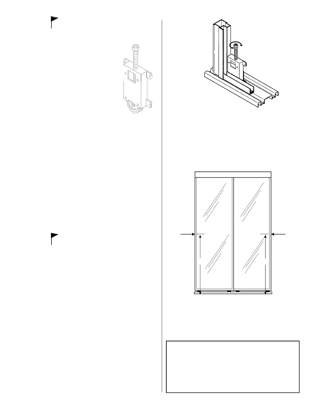
Slide the front Mirrored Glass Panel ( # 1 ) to the
side closest to the room’s entrance door (This is
how the Wardrobe Doors will be in position to look
their best). Look at the space between the door
edge and the wall. You want the door edge and the
wall to be flush. If you see space at the top or
bottom edge of the Mirrored Glass Panel ( # 1 ), turn
the adjusting screw on top of the Steel Wheel
Assembly (#13) on the lower back of the Mirrored
Glass Panel ( # 1 ) nearest the wall. Turn the screw
left or right until the Mirrored Glass Panel ( # 1 )
aligns flush with the wall. Repeat for each Mirrored
Glass Panel ( # 1 ) .
Step 6 Installing the
Clear Plastic Bumpers
Peel paper off the back of the Clear Plastic
Bumpers (#8) and place on the edge of the Mirrored
Glass Panel (#1) frame 36 up from the bottom.
The Clear Plastic Bumpers (#8) will cushion and
protect the door and wall when you close the
Wardrobe Doors (See Figure 5).
Figure 5
Concord
/ Silhouette
- I3045 - 0806
Bumper
5
36
Bumper
S
S
36
Figure 4
Concord/Silhouette Instructions 8/1/06 10:48 AM Page 5
SILHOUETTE
SUPPLEMENTAL PARTS LIST
#1 Tempered Glass Panels
#12 Bottom Mold (Top Mold same as Concord
)
#13 Concealed Wheel Assembly
Step 4 Installing the
Tempered Glass Panels
A. Make sure you have a pad or blanket to protect
the Tempered Glass Panels (#1) from scratches.
Lay Tempered Glass Panels (#1) with b a c k s i d e
up on the floor. Locate one of the Concealed
Wheel Assemblies (#13) on the bottom of a
Tempered Glass Panel (#1). With a Phillips
S c r e w d r i v e r, turn the adjusting screw to the right
to lower the roller. Do this until you have 3/4 o f
roller showing. Adjust both Concealed Wheel
Assemblies (#13) on each Tempered Glass
Panel (#1) (This will avoid scratching the
Bottom Track (#3) when installing the panels).
B. Pick up one Tempered Glass Panel (#1)and, with
the outside of the panel facing you, tilt the top of
the Tempered Glass Panel (#1) back and slip the
Tempered Glass Panel (#1) into the back runner
of the Top Channel (#2). Next, set the bottom of
the Tempered Glass Panel (#1) into the back
runner of the Bottom Track (#3).
C . For the front Tempered Glass Panel (#1), repeat
B, but place the Tempered Glass Panel (#1) into
the front runner of the Top Channel (#2) and front
runner of the Bottom Track (#3).
Step 5 Adjusting the
Tempered Glass Panels
Slide the front Tempered Glass Panel (#1) to the
side closest to the room’s entrance door (This is
how the Wardrobe Doors will be in position to look
their best). Look at the space between the door
edge and the wall. You want the door edge and
the wall to be flush. If you see space at the top or
bottom edge of the Tempered Glass Panel (#1),
turn the adjusting screw through the hole in the
side rail on the Steel Wheel Assembly (#13) on
the lower back of the Tempered Glass Panel (#1)
nearest the wall. Turn the screw left or right until
the Tempered Glass Panel (#1) aligns flush with
the wall. Repeat for each Tempered Glass P a n e l
( # 1 ) .
6
Concord
/ Silhouette
- I3045 - 0806
S
Adjustment Screw
Adjustment
Hole
#13
#2
#1
S
Concord/Silhouette Instructions 8/1/06 10:48 AM Page 6
  • Page 1 1
  • Page 2 2
  • Page 3 3
  • Page 4 4
  • Page 5 5
  • Page 6 6

Contractors Wardrobe SIL-6081SG2X Operating instructions

Type
Operating instructions

Ask a question and I''ll find the answer in the document

Finding information in a document is now easier with AI