6
M965890 Rev. 1.1 (1/19)
6
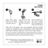
ACTIVATION; Fig. 8
Note: Four (4) “C” Cell batteries are not factory installed
inside the Flush unit.
1. Remove BATTERY TRAY (1) by loosening SCREW (3).
2. Load 4 “C” Alkaline BATTERIES (5) onto BATTERY TRAY (1).
3. Install battery tray into SIDE MOUNT OPERATOR (2) and
tighten SCREW (3) using WRENCH (4) provided.
(Note: last three turns of the wrench will activate the
automatic ushing unit)
7
ADJUSTING SENSOR DISTANCE; Fig. 8 & 9
1. Remove BATTERY TRAY (1) by loosening SCREW (3).
Fig. 9
2. Remove FRONT COVER (2) and remove SENSOR
ADJUSTMENT TOOL (4). Fig. 9
3. Install BATTERY TRAY (1) and SCREW (3) back into the
unit. Fig. 9
4. Press RANGE RESET BUTTON (5) (When object in view,
it will ash green light for 7 minute rest period). Fig. 9
5. Stand at a desired distance and use the SENSOR
ADJUSTMENT TOOL (4) to turn SENSOR ADJUSTMENT
SCREW (6) all the way counter clockwise and then turn
clockwise until green L.E.D begins to Flash. Fig. 9
8
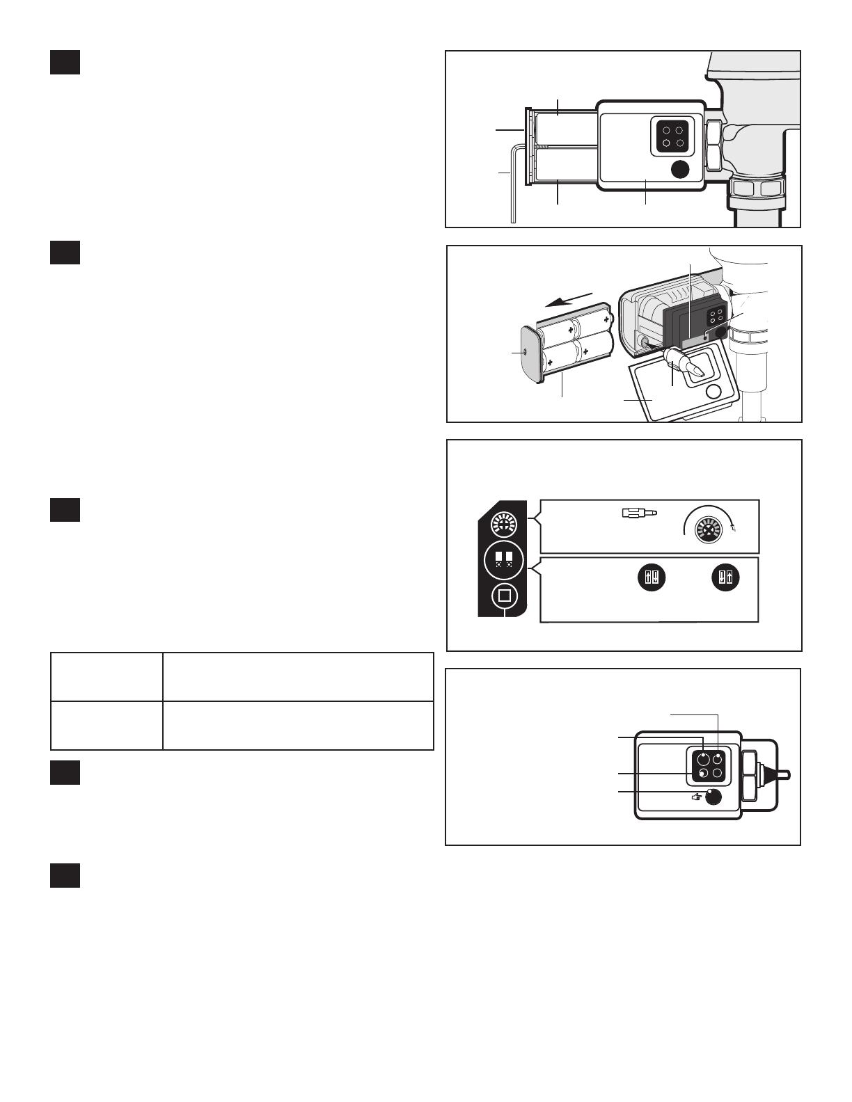
ADJUSTING MODES OF OPERATION;
Fig. 9 &10
The FLUSH unit includes different modes of operation.
Remove FRONT COVER (2) by loosening up SCREW (3) by
using a wrench and removing BATTERY TRAY (1). Refer to
the “Mode Adjustment Guide” for switch settings. The “Mode
Adjustment Guide” can also be found on the inside of side
cover for your convenience.
9
BATTERY REPLACEMENT; Fig. 8
1. Remove BATTERY TRAY (1) by loosening SCREW (3).
2. Replace 4 “C” Alkaline BATTERIES (2). (Note: Replace all
4 batteries at the same time for proper function)
10
VISUAL INDICATOR GUIDE; Fig. 12
User – In View L.E.D (1) – 5 second after a user is in view a
green light ashes 3 times.( during a startup sequence the green
light ashes constantly for 7 minutes when a user is in view)
Battery L.E.D (2) – Yellow light ashes which indicates that the
batteries all 4 “C” Alkaline batteries will need to be replaced.
Object Lock Sensor (3) – Detects user or object.
Mechanical Push Button – Allows manual activation of ush
when needed and when batteries are drained.
1
Fig. 9
6
5
+
-
2
3
4
RANGE
RESET
BUTTON
OPERATION
FEATURES
- -
+
-
+ +
1
5
2
3
4
Fig. 8
Fig. 10
1
ON
2
1
ON
2
-
+
Urinal Model Only
Use Sensor
Adjustment
Tool
Near
Switch 1
24 Hours Flush On
Switch 2
Alarm Tone Off
Far
1
ON
2
Switch 1
24 Hours Flush Off
Switch 2
Alarm Tone On
Sensor Range
Adjustment
Screw
Operation
Features
Urinal Model Only
Fig. 12
User – In View L.E.D
Object Lock Sensor
Battery L.E.D
Mechanical Push Button
24 Hour
Flush On
Allows the ush valve to automatically
ush after 24 hour period of non-use to
maintain the trap seal.
Alarm Tone
It beeps when the battery is running low. If
you don’t want it to beep, you can turn off
this feature, with the toggle switches.
LOCATED INSIDE FRONT COVER