MOUNT-KB35A

Vivo MOUNT-KB35A User manual

  • Hello! I have reviewed the instruction manual for the VIVO MOUNT-KB35A Keyboard Tray. This document provides step-by-step instructions for assembling and installing the wall-mounted keyboard tray, including options for wood stud or concrete/brick mounting. It also details how to adjust the tension and tilt of the tray. I'm ready to answer your questions about this device.
  • What is the weight capacity of this keyboard tray?
    What tools are needed for the assembly?
    How do I adjust the tension for different keyboard weights?
Black Pneumatic Wall Mounted Keyboard Tray
Scan the QR code with your mobile device or follow the link
for helpful videos and specications related to this product.
Instruction Manual
https://vivo-us.com/products/mount-kb35a
SKU: MOUNT-KB35A
[email protected]om www.vivo-us.com 309-278-5303
Chat live with an agent!
GET IN TOUCH | Monday-Friday from 7:00am-7:00pm CST
2
WARNING!
If you do not understand these directions, or if you have any doubts about the safety of the installation,
please call a qualied technician. Check carefully to make sure there are no missing or defective parts.
Improper installation may cause damage or serious injury. Do not use this product for any purpose that is
not explicitly specied in this manual. Do not exceed weight capacity. We cannot be liable for damage or
injury caused by improper mounting, incorrect assembly or inappropriate use.
17.6lbs
(8kg)
DO NOT EXCEED WEIGHT CAPACITY.
Failure to do so may result in serious injury.
WARNING: CHOKING HAZARD
SMALL PARTS - NOT FOR CHILDREN UNDER 3 YEARS. ADULT SUPERVISION IS REQUIRED.
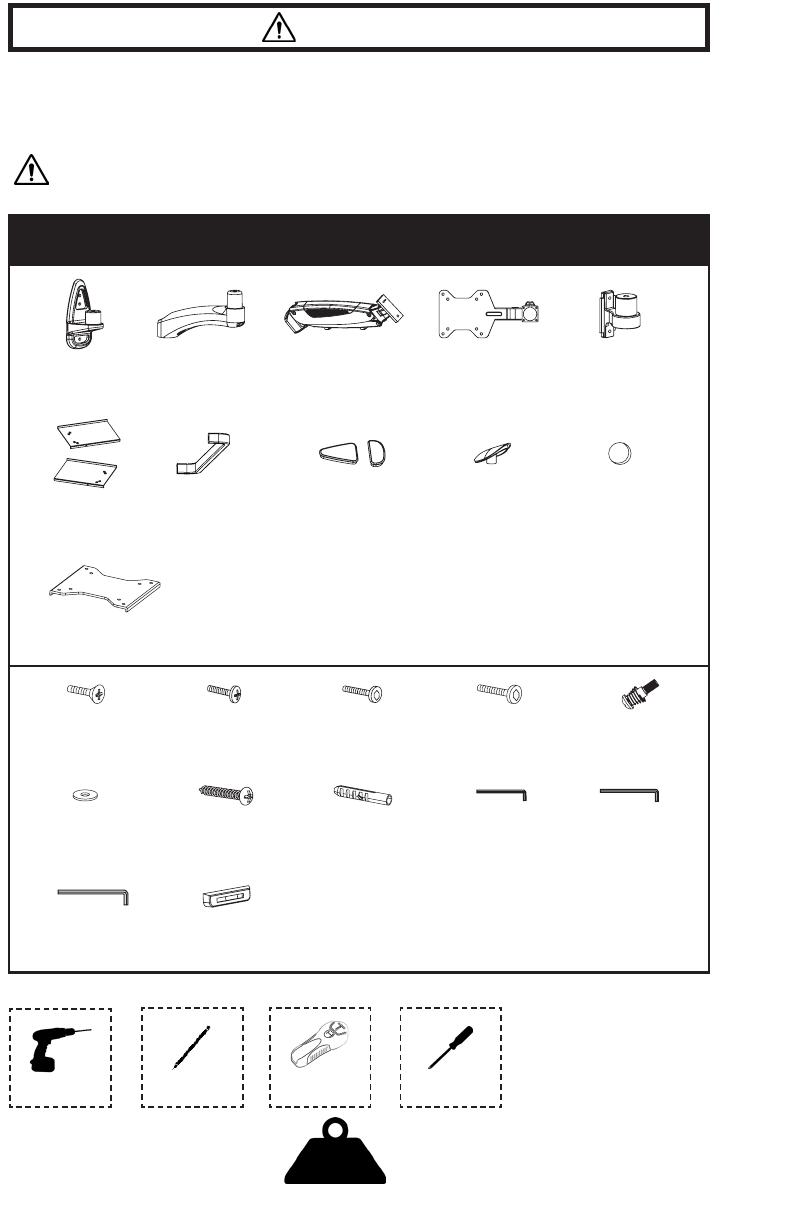
PACKAGE CONTENTS
A (x1)
Wall Plate
S-A (x8)
M5x10mm Screw
S-B (x2)
M4x6mm Screw
NOTE: SOME HARDWARE MAY NOT BE USED
Drill Pencil Stud Finder Phillips
Screwdriver
B (x1)
Arm Extension
C (x1)
Arm
D (x1)
Keyboard Bracket
E (x1)
Mount Fitting
F (x1)
Keyboard Tray
G (x1)
Handle
S-C (x2)
M6x16mm Screw
S-D (x1)
M5x18mm Screw
S-E (x2)
M6x25mm Screw
M-A (x3)
M6x50mm Screw
M-B (x3)
Concrete Anchor
S-F (x1)
M6.5 Washer
H (x1)
Wall Plate Cover
I (x2)
Cap
J (x5)
Pad
T-A (x1)
3mm Allen Wrench
T-B (x1)
4mm Allen Wrench
T-C (x1)
5mm Allen Wrench
T-D (x1)
Level
TOOLS NEEDED
K (x1)
Connecting Plate
3
ASSEMBLY STEPS
STEP 1
OPTION A: Wood Stud Installation
Place Wall Plate (A) against the wall and mark drilling locations with a pencil. Use of a stud
nder and Level (T-D) is highly recommended. Drill 1.2” (30mm) deep holes using a .12”
(3mm) bit, then attach Wall Plate (A) to wall using M6x50mm Screws (M-A) and a Phillips
screwdriver. Assemble Wall Plate Covers (H) to Wall Plate (A).
OPTION B: Concrete/Brick
Place Wall Plate (A) against the wall and mark drilling locations with a pencil. Use of a
Level (T-D) is highly recommended. Drill 2” (50mm) deep holes using a .31” (8mm) bit,
press Concrete Anchors (M-B) into holes, then attach Wall Plate (A) to wall using M6x50mm
Screws (M-A) and a Phillips screwdriver. Assemble Wall Plate Covers (H) to Wall Plate (A).
3mm
30mm(1.2 )
(0.12 )
8mm
50mm(2.0 )
(0.31 )
A
T-D
M-A
S-A
T-D
M-B
A
H
H
4
STEP 2
Slide Arm Extension (B) onto Wall Plate (A). Secure using M6x25mm Screw (S-E) and Cap
(I) with a Phillips screwdriver.
STEP 3
Attach Mount Fitting (E) to Arm (C) using M6x16mm Screws (S-C) and M6.5 Washer (S-F).
Use M6.5 Washer (S-F) with top screw inserted through slot. Tighten the M6x16mm Screws
(S-C) using the 4mm Allen Wrench (T-B).
B
A
I
S-E
S-C
T-B
S-F
E
C
5
STEP 4
Assemble both halves of Keyboard Tray (F) to Keyboard Bracket (D) and Connecting Plate
(K) using M5x10mm Screws (S-A) and a Phillips screwdriver.
NOTE: Make sure the lip on Keyboard Tray (F) is facing up in the back, and the handle
mounting holes are in the front.
STEP 5
Secure Handle (G) to Keyboard Tray (F) using M4x6mm Screws (S-B) and a Phillips
screwdriver.
D
S-A
G
S-B
F
F
K
6
STEP 6
Mount Keyboard Bracket (D) to Arm (C) and secure using 4mm Allen Wrench (T-B).
STEP 7
Assemble Arm (C) to Arm Extension (B). Secure using M6x25mm Screw (S-E) and Cap (I)
with a Phillips screwdriver. Remove adhesive backing from Pads (J) and place them on
Keyboard Tray (F).
T-B D
C
J
C
B
S-E
I
F
7
STEP 8
Adjust the tension in Arm (C) using 5mm Allen Wrench (T-C). Turn clockwise to reduce
tension for lighter keyboards and counter-clockwise to increase tension for heavier
keyboards. Lock the rotation of Arm (C) by tightening the set screw in back using 3mm Allen
Wrench (T-A). Adjust Keyboard Tray (F) minimum tilt angle by turning the set screw under
Keyboard Bracket (D) counter-clockwise using 3mm Allen Wrench (T-A).
C
T-C
F
T-A
T-A
D
LAST UPDATED: 06/10/2022
REV1
Open Monday - Friday 7:00am - 7:00pm CST,
our dedicated support team can oer immediate assistance with rapid response times. If any
parts are received damaged or defective, please contact us. We are happy to replace parts to
ensure you have a fully functioning product.
FOR MORE VIVO PRODUCTS, CHECK OUT OUR WEBSITE AT: www.vivo-us.com
Love your new VIVO setup and want to share?
Tag us in your photo! @vivo_us
[email protected] AVG. RESPONSE TIME (within oice hrs): 1HR 8M
- 23% within < 15m
- 38% within < 30m
- 61% within < 1hr
- 83% within < 2hr
- 92% within < 3hr
AVG. RESOLUTION TIME (within oice hrs): < 15 M
www.vivo-us.com
Chat live with an agent!
AVG. RESOLUTION TIME (within oice hrs): 5M 4S
309-278-5303
/