GeneralAire GF-4200PFT Installation guide

Type
Installation guide

GeneralAire GF-4200PFT is an electronically controlled pulsed flow humidifier designed for forced air heating systems. It can be installed on either the supply or return plenum and is reversible for right or left-hand installations. The GF-4200PFT features a 5-year limited warranty and includes a vapor pad, solenoid valve, bypass damper with duct collar, manual humidistat, transformer, and hardware kits.

GeneralAire GF-4200PFT is an electronically controlled pulsed flow humidifier designed for forced air heating systems. It can be installed on either the supply or return plenum and is reversible for right or left-hand installations. The GF-4200PFT features a 5-year limited warranty and includes a vapor pad, solenoid valve, bypass damper with duct collar, manual humidistat, transformer, and hardware kits.

Installation Manual
Model GF-4200PFT Evaporative Humidifiers
®
Please Read And Save These Instructions
Canadian General Filters, Ltd.
400 Midwest Road
Toronto, ON M1P3A9
Toll Free: (888) 216-9184
www.generalaireiaq.ca
IMPORTANT: To ensure your safety and the
longevity of your unit, we recommend:
Contacting a licensed contractor to perform
maintenance or repairs.
Changing your Vapor Pad® at the start of each
heating season.
!
Inside The Box
• GF-GA900 Vapor Pad®
• Pulse Solenoid
• Integral Bypass Damper With Duct Collar
• Manual Humidistat
• 24V Transformer
• Hardware Kits
• 1/4" Diameter plastic supply tubing for hot or cold water applications
• 6" Diameter rigid and exible by-pass duct
• Electrical wire
• 1/2 x 1/2 x 1/4 CSA approved ball valve
HSA055 Pulse Electronic Controller
• Drain Hose
• WARNING: DISCONNECT ELECTRICAL POWER
BEFORE BEGINNING INSTALLATION.
WARNING: Do not install where ambient temperatures fall below 32°F / 0° C or where plenum temperatures exceed 200° F / 93° C.
For maximum evaporative capacity, install this humidier on the warm air supply plenum.
!
!
WARNING!
This symbol and the word "WARNING" indicates:
IMPORTANT INSTRUCTIONS!
Failure to heed CAUTION! or WARNING! can result in serious injury or death.
CAUTION!
This symbol and the word "CAUTION" indicates:
IMPORTANT INSTRUCTIONS!
!
!
!
!
Canadian General Filters
Limited
Plenum Installation Location: Model GF-4200PFT
humidiers may be installed on either the return or supply
plenum of a forced air handling system. The humidier's bypass
panel is reversible and can be mounted on the right or left side
of the humidier. Select a location for the humidier that allows
for service and maintenance.
Vertical
Installation
Options
Return Return
Supply Supply
Horizontal Installation
Drain Line
Drain Line
GF-4200PFT
1. Your new humidier carries a 5-year limited warranty.
2. For our complete warranty policy visit www.generalaireiaq.ca.
2
INSTALLATION
PREPARING THE UNIT
1. Install and fasten the water diffuser, the long plastic piece, with two screws
(#6 x 1/2") inside the top part of the humidier.
2. Install the solenoid valve (mounted on a plastic bracket) outside of the top of the
humidier.
3. While supporting the water diffuser with one hand, insert the plastic tube
protruding from the valve into the hole in the middle of the top part of the
humidier, making sure that the plastic tubing is rmly seated in the hole of the
water diffuser.
4. Fasten the valve assembly to the unit with screws #6 x 1/2".
PREPARING THE DUCT
Note: Installation on the hot air duct will improve humidity output.
1. Once a location is determined for placement on the duct, attach the template
to the duct.
2. Punch and drill the four corners for the opening and the six fastening holes
with a 3/32" drill.
3. Remove the template and complete the opening outline.
4. Cut the opening in the plenum.
ATTACHING THE UNIT TO THE DUCT
Note: Use the six screws provided (#8 x 3/4") to attach humidier body to the duct.
1. Hold the humidier body to the duct opening, ensuring the locating ribs t into
the duct opening.
2. Check that the humidier is level from left to right, then fasten to the duct.
INSTALLING THE COLLARS AND FLEX DUCT
1. Install the 6" duct collar in a location opposite the duct with the humidier body.
2. Slide the bypass panel into the side opening of the humidier until it snaps.
3. Measure the required ex duct length from the duct collar to the bypass panel so
it does not sag. Cut the ex duct to length and install it as shown. Secure ex duct
using screws, foil tape and / or duct tape.
Electric Valve
Water Diffuser
Ensure Template
Is Level
®
TM
Flex Duct
Duct
Collar
6" Straight Duct
This unit is reversible. When changing the humidier left or
right, make sure you place the evaporative pad the correct
way. The frame is marked "FRONT"; see "INSTALLING THE
VAPOR PAD" for further details.
INSTALLING THE DRAIN TUBE
1. First slip the hose clamp over the hose.
2. Push the drain tube (1/2" I.D.) over the drain tting located at the bottom
of the unit and secure it in place with the hose clamp.
3. Make sure the tube has no bends so that water can easily ow through
the tube straight to the drain.
3
®
INSTALLATION
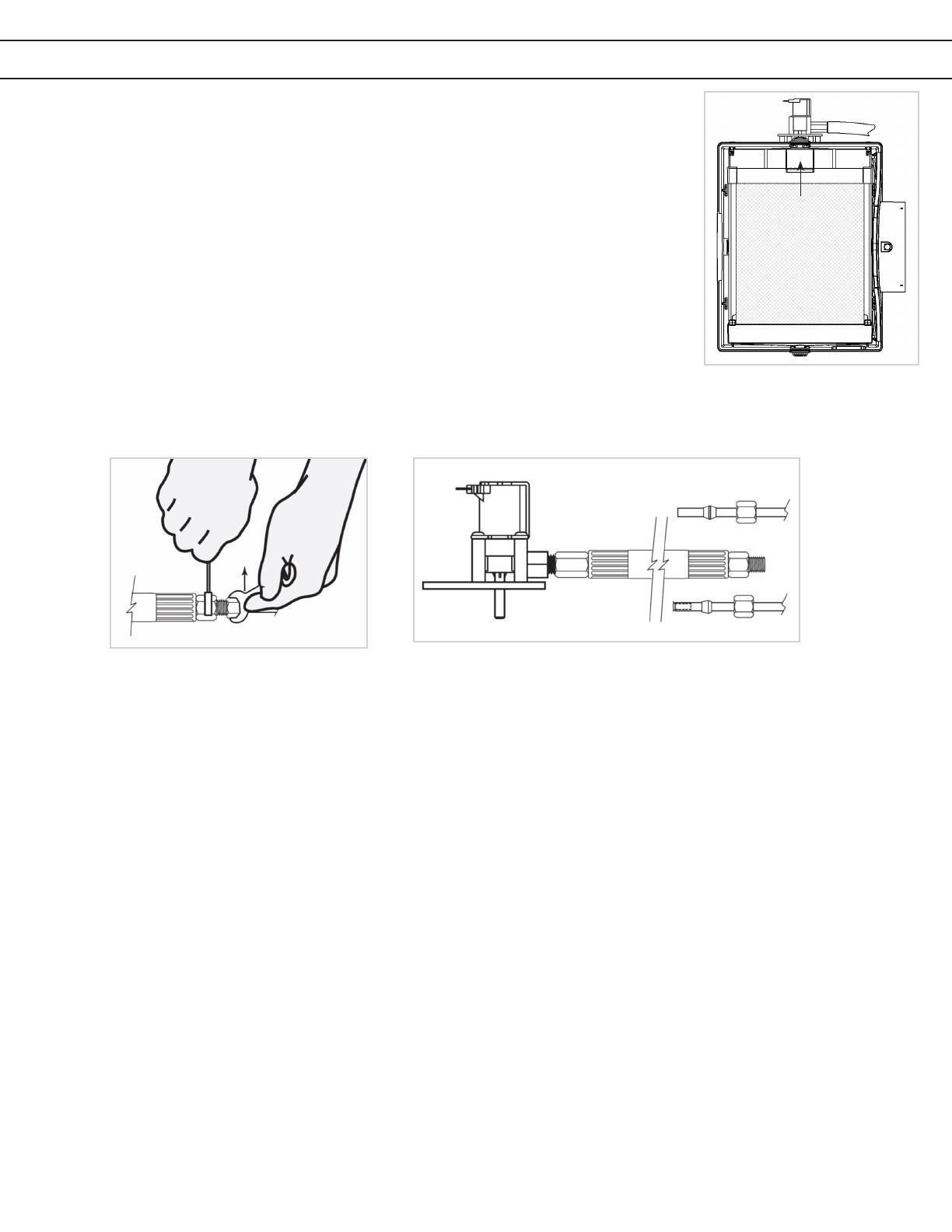
INSTALLING THE VAPOR PAD (Shown at Right)
1. Slide the pad and frame into the bottom part of the humidier.
2. Push the pad against the back opening of the humidier until it locks (snaps)
into place with the pad retainer.
CONNECTING THE WATER SUPPLY TUBING TO THE WATER HAMMER
ABSORBER AND VALVE (Shown Below)
1. Install the water supply tubing on the other side of the rubber hose (a compression tting receives the
water supply hose).
2. Slip the brass compression nut onto the plastic supply tube, then the nylon sleeve with its most tapered end towards the end of the tube.
3. Push the supply tube fully into the brass compression tting. Tighten the brass compression nut using the double wrench method in order
to apply the torque on the tting only.
Lock the Pad
In Place
INSTALLING THE QUICK-CONNECT VALVE
Note: The water supply can be taken from the nearest suitable cold, hot, softened or unsoftened water line. The use of service hot water
(140°F / 6°C Max) increases output.
1. Cut the tubing and pipe to desired length, making sure cuts are square and all burrs are removed.
2. Push the tting onto the end of the pipe. The tting will grip before it seals.
3. Ensure that the tubing / pipe is pushed into the tting until the end is fully seated into the internal tube stop.
HOW THE HSA055 PULSE CONTROLLER WORKS
The HSA055 pulse controller works by turning the water ON for 4 seconds, then turning it OFF for 30 seconds. This xed setting reduces
excess water that may ow down the drain without reducing humidity output.
INSTALLING THE ELECTRONIC CONTROLLER:
The HSA055 is factory set at NO TEMP (TEST), with settings for HIGH TEMP and LOW TEMP.
1. The NO TEMP (TEST) setting is used when the humidifier is supplied power from the furnace. The unit will run as long as there is power
AND the humidistat is calling for more humidity.
2. The LOW TEMP setting is used for furnaces that generate less heat, such as those with a heat pump. The unit may operate for a short
while after the furnace has stopped due to residual heat in the duct.
3. The HIGH TEMP setting is used for furnaces that generate more heat, typically oil or gas furnaces. You may have to try both settings to
see which one is right for you.
4. To choose the setting on the controller, set the dip-switches, as shown on the controller. For HIGH and LOW settings the controller must
be installed on the warm air duct with two screws (#8 x 3/4"). There are two lights on the controller: the green LED means there is
power to the controller and the blue LED cycles on as the valve opens. When switched ON by the humidistat, the controller opens the
electric valve for approximately 4 seconds and then closes the valve for another 30, and so on. Please use the template to drill the 3
holes.
Plastic
Copper
4
INSTALLATION, CONTINUED
Canadian General Filters, Ltd. 400 Midwest Road Toronto, ON M1P3A9
Toll Free: (888) 216-9184 www.generalaireiaq.ca
Canadian General Filters
Limited
INSTALLING THE 120 VOLT TRANSFORMER
Note: Do not install it on a furnace supplied with a different voltage.
1. Connect the transformer primary to the relay activated when the furnace is in a heating cycle. Some furnaces have power terminals that
can be used for accessories. (Refer to the furnace installation manual.)
BASIC INSTALLATION UTILIZING THE FURNACE-SUPPLIED 24V CIRCUIT BOARD
Electronic Controller C
G
R
W*
HSA 055 Humidistat
NO C
Dip
Switch
24V From
Furnace Circuit
Board
Valve
Valve 24 Vac
Electronic Controller
HSA 055 Humidistat
Transformer
NO C
Dip
Switch
120 Vac
Black White
Valve
Valve 24 Vac
INSTALLING THE HUMIDISTAT
Note: Install the humidistat on the return duct. Never install below humidier.
1. Refer to the installation manual accompanying the humidistat.
STARTING YOUR HUMIDIFIER
1. Open the water supply valve, put the furnace power back on and start the furnace in a heating cycle. Set the humidistat to the maximum setting. After
a few ON/OFF cycles of the electric valve, you should see water owing through the drain tube. Check that the water is evenly distributed by the water
diffuser across the pad. Carefully check that both ends of the water supply tube are rmly held in place by their respective compression tting. Set
the humidistat according to the recommended setting (40-60% RH). Check the system several times to make sure there is a free ow in the drain
tube and there is no leak before leaving the installation unattended. When everything is working ne, afx the nameplate to the humidier cover.
MAINTENANCE
1. Replace your GF-GA900 Vapor Pad® With Frame at the beginning of each heating season.
2. Remove any scale buildup by soaking in vinegar and water.
5
WARRANTY
Model GF-4200PFT/PXL
Electronically Controlled
Pulsed Flow Humidifier
Please read the instructions carefully before starting the
installation. This humidifier must be installed by a
qualified heating and air conditioning contractor.
The Pro 600 model can be installed on either the supply or return plenum
of a forced air heating system. It is easily reversible for right or left hand.
The total dimensions are: 15" x 15" x 9". The opening in the duct is
9-1/4" x 8-1/4". In selecting the best location for the unit, please take both
dimensions and serviceability in consideration. If the furnace is equipped
with a central cooling system, the damper of the unit should be closed
during the cooling season.
TEMPLATE # 3
for electronic controller
Your new humidifier carries a 5-year limited warranty. For our complete warranty policy and registration visit www.generalaireiaq.ca.
Our
Brands
®
216- 9184
www.generalaireiaq .ca
400 Midwest Rd.
Toronto, ON M1P 3A9
Canada Toll Free: (888)
Last Updated
01-2022
  • Page 1 1
  • Page 2 2
  • Page 3 3
  • Page 4 4
  • Page 5 5

GeneralAire GF-4200PFT Installation guide

Type
Installation guide

GeneralAire GF-4200PFT is an electronically controlled pulsed flow humidifier designed for forced air heating systems. It can be installed on either the supply or return plenum and is reversible for right or left-hand installations. The GF-4200PFT features a 5-year limited warranty and includes a vapor pad, solenoid valve, bypass damper with duct collar, manual humidistat, transformer, and hardware kits.

Ask a question and I''ll find the answer in the document

Finding information in a document is now easier with AI