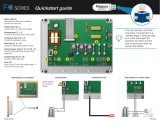
Phason RS485-FD Installation guide

Type
Installation guide

Phason RS485-FD converts any USB port on your computer to a four-wire RS485 serial communication port, allowing communication between your computer and Phason networkable devices. Ideal for single or multi-channel systems, it supports up to 64 devices in a multi-channel OMNI Select system with the Phason Communication Hub (PCH). The RS485-FD ensures secure and reliable data transmission, making it suitable for various applications, including industrial automation, building management, and security systems.

Phason RS485-FD converts any USB port on your computer to a four-wire RS485 serial communication port, allowing communication between your computer and Phason networkable devices. Ideal for single or multi-channel systems, it supports up to 64 devices in a multi-channel OMNI Select system with the Phason Communication Hub (PCH). The RS485-FD ensures secure and reliable data transmission, making it suitable for various applications, including industrial automation, building management, and security systems.

Phason
25048009 1 of 5
RS485-FD Converter
The RS485-FD Converter (model RS485-FD) converts any USB
port on your laptop or desktop computer to a four-wire RS485
serial communication port.
Communication overview
All Phason networkable devices communicate with the computer
using four-wire RS485 serial communication. The RS485-FD
provides a way for the Phason software on your computer to
communicate with the devices along a communication channel.
A communication channel is a continuous line of cable connecting all devices in the series, in other
words, a “daisy chain”. The last device on a communication channel must have the termination
resistors in place, or a termination module installed.
Single-channel systems
A single-channel system consists of the computer, RS485-FD Converter, and the Phason devices.
The last device must have the termination resistors in place, or a termination module installed.
Multi-channel systems
A multi-channel OMNI Select system requires a Phason Communication Hub (PCH). The PCH has
4 communication channels and can communicate with up to 64 devices.
Phason
25048009 2 of 5
Installing the RS485-FD Converter
There are three steps to installing the RS485-FD Converter:
1. Connecting the communication and common reference wiring
2. Connecting the RS485-FD to the computer
3. Installing the software drivers on the computer
Communication cable requirements
The following types of cable are acceptable. Phason does not recommend other types of wire.
Unshielded twisted pair (UTP), category 5 (CAT5)
Shielded twisted pair (STP), CAT5
Proper connector alignment and wiring
There are three possible connector types on Phason devices. The four-positions, A
B C D, are common to all models. Some models have five positions and include E
for common reference wiring. The six-position connectors that include position 1
are included on the RS485-FD and Phason Communication Hub.
Using consistent wiring helps eliminate communication connection errors and
makes troubleshooting much easier. Use the wire colors shown below when
connecting all devices to the communication system.
Wire function
RS485
PCH (if installed)
All devices
1 alarm signal*
1 white/green
1 white/green
A communication [ Tx ]
A blue
A blue
A blue
B communication [ Tx + ]
B white/blue
B white/blue
B white/blue
C communication [ Rx ]
C orange
C orange
C orange
D communication [ Rx + ]
D white/orange
D white/orange
D white/orange
E common reference
E green
E green
E green
* Used only in OMNI Select systems with the Phason Communication Hub (PCH). For information about connecting a
PCH see the installation guide for that specific product.
Phason
25048009 3 of 5
Common mistakes in communication wiring
Not using the correct type of communication cable the communication cable must be twisted
pair cable, category 5 (CAT5). You can use either unshielded twisted pair (UTP) or shielded
twisted pair (STP) cable. Phason does not recommend other types of wire.
There are additional guidelines to follow when using STP cable. For more information, read
Using shielded twisted pair (STP) cable on page 4.
Running the communication cable in the same conduit as, or beside AC power cables
routing communication cable in the same conduit as, or beside AC power cables, can cause
electrical interference and communication failures. Follow the guidelines below when routing
communication cable.
Do not run the cable in the same conduit as AC power cables.
Do not run the cable beside AC power cables or near electrical equipment.
When crossing other cables or power lines, cross them at a 90-degree angle.
Not continuing the communication wiring properly all the devices on the communication
channel must be connected in series (in a daisy chain) and the wire must be continued properly
from one device to the next. When continuing the communication wiring from one device to the
next, the wires must be connected as shown in the following diagram.
Not terminating the last device on the communication channel on all systems, the last device
on the communication channel must have the termination resistors in place or a termination
module installed. You must remove the termination resistors from all devices, except the last
one on the communication channel.
The termination resistors are located on the circuit board of all networkable devices except the
PBx Power Block, which has termination jumpers.
Phason
25048009 4 of 5
Using shielded twisted pair (STP) cable
The advantage of using STP cable is that it can improve communications by reducing
electromagnetic interference. The drawback of STP cable is that it requires more care during
installation. If the shielding is connected incorrectly, shielded cable can cause more problems than it
solves.
How to install shielded cable
When installing shielded cable, you must connect the shielding to the building ground at one end
only. Phason recommends connecting the cable to the building ground near the computer.
When connecting the devices along the communication channel (daisy-chain), connect the shielding
of the incoming cable to the shielding of the outgoing cable. Do not connect the shielding to the
device or to anything else. At the last device on the daisy chain, do not connect the shielding; leave it
unconnected.
Connecting the communication and common reference wiring
1. Connect all the devices in series. For example, A on the RS485-FD to A on the first device, to A
on the second device, and so on. Use the wires specified in the table on page 2 and follow the
guidelines on page 2.
2. Remove the termination resistors from each device, except for the last one on the communication
channel. The last device must have the termination resistors in place. For the location of the
termination resistors, see the installation guide for each specific product.
For controls having only four-position connectors, it is a good idea to leave the
communication cable one foot longer than is needed for connecting to the
terminals (A, B, C, and D). You can then use the extra length of wire to connect
to a reference point on the circuit board in place of the E terminal.
For information about which terminal to use in place of the E terminal, see the
user manual for the specific device, or contact Phason Customer Support.
Phason
25048009 5 of 5
Connecting the RS485-FD to the computer
After connecting the communication and
common reference wiring to all the devices,
connect the RS485-FD to the computer.
1. Plug the communication connector into the
communication socket on the RS485-FD.
2. Connect the square end of the USB cable to
the RS485-FD and the rectangular end
directly to one of your computer’s USB ports.
Installing the software drivers
The USB stick that came with the RS485-FD includes software drivers for Windows 7 and higher.
The first time you connect the RS485-FD, your operating system will ask you for drivers. Drivers
tell the computer how to operate the RS485-FD.
There are two drivers to install: one called USB Serial Converter, the other called USB Serial Port.
After both drivers have been successfully installed, the power LED on the RS485-FD should light
up green. To install the drivers, follow the instructions below.
Windows 7 and higher
1. Insert the USB stick into one of your computer's USB ports.
Windows might install drivers for the USB stick.
The Autoplay window should display. If the window does not
display, see the NOTE below.
2. In the Autoplay window, select Open folder to view files.
Windows Explorer displays.
3. Double-click Install_RS485_Drivers.exe.
4. Follow the instructions on the screen to install the drivers for the
USB Serial Converter and USB Serial Port from the USB stick.
5. When installation has finished, connect the RS485-FD to one of
your computer's USB ports.
Phason
25048009 6 of 5
Loopback testers
Loopback tests help verify the integrity of the communication line. If you have communication
problems, you should perform loopback tests before replacing hardware. To perform loopback
tests, you need a test utility (included with all Phason software) and loopback connectors.
During loopback tests, the computer sends out information along the communication channel. The
information “bounces back” when it gets to the loopback connector. The computer compares the
information it receives back; if it is the same as the information sent out, then both the send (TX)
and receive (RX) lines are intact.
There are two types of loopback connectors; each type is for testing at different locations along the
communication channel. When loopback testing, it is best to start at the computer and then work
outward along the communication channel. For more-detailed information about loopback tests and
how to use the test utilities, contact Phason Customer Support.
Converter loopback connector
The Converter loopback connector is for testing the
RS-485 Converters for PCH channels.
Daisy-chain loopback connector
The daisy-chain loopback connector is for testing
individual connections at the devices on the
communication channel. For devices with a five or
six-position male connector, the A B C D pins of the
connector must line up as shown in the diagram
phason.ca [email protected] International: 204-233-1400 Toll-free North America: 800-590-9338
  • Page 1 1
  • Page 2 2
  • Page 3 3
  • Page 4 4
  • Page 5 5
  • Page 6 6

Phason RS485-FD Installation guide

Type
Installation guide

Phason RS485-FD converts any USB port on your computer to a four-wire RS485 serial communication port, allowing communication between your computer and Phason networkable devices. Ideal for single or multi-channel systems, it supports up to 64 devices in a multi-channel OMNI Select system with the Phason Communication Hub (PCH). The RS485-FD ensures secure and reliable data transmission, making it suitable for various applications, including industrial automation, building management, and security systems.

Ask a question and I''ll find the answer in the document

Finding information in a document is now easier with AI