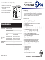
PDQ PS440B is a reliable power supply designed to provide continuous power to various electrical devices, such as electrified mortise and cylindrical locks, electric strikes, mag locks, and motorized exit devices. It features regulated 24VDC output with a 4 Amp continuous rating and a 6 Amp boost at 20% duty cycle, making it suitable for applications requiring brief surges of power. The PS440B also includes independent, solid-state triggered inputs for access control and a fire alarm link for added safety.
PDQ PS440B is a reliable power supply designed to provide continuous power to various electrical devices, such as electrified mortise and cylindrical locks, electric strikes, mag locks, and motorized exit devices. It features regulated 24VDC output with a 4 Amp continuous rating and a 6 Amp boost at 20% duty cycle, making it suitable for applications requiring brief surges of power. The PS440B also includes independent, solid-state triggered inputs for access control and a fire alarm link for added safety.


-
 1
1
-
 2
2


PDQ PS440B is a reliable power supply designed to provide continuous power to various electrical devices, such as electrified mortise and cylindrical locks, electric strikes, mag locks, and motorized exit devices. It features regulated 24VDC output with a 4 Amp continuous rating and a 6 Amp boost at 20% duty cycle, making it suitable for applications requiring brief surges of power. The PS440B also includes independent, solid-state triggered inputs for access control and a fire alarm link for added safety.
Ask a question and I''ll find the answer in the document
Finding information in a document is now easier with AI
Other documents
-
All Security Equipment ASE Power Supply Control Box User manual
-
 CAMDEN DOOR CONTROLS CX-PS150UL User manual
-
Altronix eFlow104NA8 Series Installation guide
-
Altronix eFlow4N Series Installation guide
-
Altronix EFLOW3N Installation guide
-
 NAPCO SLE-LTEV-CFB Installation Instructions Manual
-
Altronix eFlow104NK1 Installation guide
-
Altronix Maximal3F Installation guide
-
Altronix Maximal3FD Installation guide
-
Altronix MAXIMAL77F Installation guide

