Page is loading ...

Computer-Based
Instruments
NI 5620 User Manual
Digitizer for PXI
NI 5620 User Manual
™
June 2001 Edition
Part Number 322949B-01

Support
Worldwide Technical Support and Product Information
ni.com
National Instruments Corporate Headquarters
11500 North Mopac Expressway Austin, Texas 78759-3504 USA Tel: 512 794 0100
Worldwide Offices
Australia 03 9879 5166, Austria 0662 45 79 90 0, Belgium 02 757 00 20, Brazil 011 284 5011,
Canada (Calgary) 403 274 9391, Canada (Montreal) 514 288 5722, Canada (Ottawa) 613 233 5949,
Canada (Québec) 514 694 8521, Canada (Toronto) 905 785 0085, China (Shanghai) 021 6555 7838,
China (ShenZhen) 0755 3904939, Denmark 45 76 26 00, Finland 09 725 725 11, France 01 48 14 24 24,
Germany 089 741 31 30, Greece 30 1 42 96 427, Hong Kong 2645 3186, India 91805275406,
Israel 03 6120092, Italy 02 413091, Japan 03 5472 2970, Korea 02 596 7456, Malaysia 603 9596711,
Mexico 5 280 7625, Netherlands 0348 433466, New Zealand 09 914 0488, Norway 32 27 73 00,
Poland 0 22 528 94 06, Portugal 351 1 726 9011, Singapore 2265886, Spain 91 640 0085,
Sweden 08 587 895 00, Switzerland 056 200 51 51, Taiwan 02 2528 7227, United Kingdom 01635 523545
For further support information, see the Technical Support Resources appendix. To comment on the
documentation, send e-mail to [email protected].
Copyright © 2001 National Instruments Corporation. All rights reserved.

Important Information
Warranty
The NI 5620 is warranted against defects in materials and workmanship for a period of one year from the date of shipment, as evidenced by
receipts or other documentation. National Instruments will, at its option, repair or replace equipment that proves to be defective during the
warranty period. This warranty includes parts and labor.
The media on which you receive National Instruments software are warranted not to fail to execute programming instructions, due to defects
in materials and workmanship, for a period of 90 days from date of shipment, as evidenced by receipts or other documentation. National
Instruments will, at its option, repair or replace software media that do not execute programming instructions if National Instruments receives
notice of such defects during the warranty period. National Instruments does not warrant that the operation of the software shall be
uninterrupted or error free.
A Return Material Authorization (RMA) number must be obtained from the factory and clearly marked on the outside of the package before
any equipment will be accepted for warranty work. National Instruments will pay the shipping costs of returning to the owner parts which are
covered by warranty.
National Instruments believes that the information in this document is accurate. The document has been carefully reviewed for technical
accuracy. In the event that technical or typographical errors exist, National Instruments reserves the right to make changes to subsequent
editions of this document without prior notice to holders of this edition. The reader should consult National Instruments if errors are suspected.
In no event shall National Instruments be liable for any damages arising out of or related to this document or the information contained in it.
E
XCEPT AS SPECIFIED HEREIN,NATIONAL INSTRUMENTS MAKES NO WARRANTIES, EXPRESS OR IMPLIED, AND SPECIFICALLY DISCLAIMS ANY WARRANTY OF
MERCHANTABILITY OR FITNESS FOR A PARTICULAR PURPOSE
.CUSTOMER’S RIGHT TO RECOVER DAMAGES CAUSED BY FAULT OR NEGLIGENCE ON THE PART OF
NATIONAL INSTRUMENTS SHALL BE LIMITED TO THE AMOUNT THERETOFORE PAID BY THE CUSTOMER.NATIONAL INSTRUMENTS WILL NOT BE LIABLE FOR
DAMAGES RESULTING FROM LOSS OF DATA
, PROFITS, USE OF PRODUCTS, OR INCIDENTAL OR CONSEQUENTIAL DAMAGES, EVEN IF ADVISED OF THE POSSIBILITY
THEREOF
. This limitation of the liability of National Instruments will apply regardless of the form of action, whether in contract or tort, including
negligence. Any action against National Instruments must be brought within one year after the cause of action accrues. National Instruments
shall not be liable for any delay in performance due to causes beyond its reasonable control. The warranty provided herein does not cover
damages, defects, malfunctions, or service failures caused by owner’s failure to follow the National Instruments installation, operation, or
maintenance instructions; owner’s modification of the product; owner’s abuse, misuse, or negligent acts; and power failure or surges, fire,
flood, accident, actions of third parties, or other events outside reasonable control.
Copyright
Under the copyright laws, this publication may not be reproduced or transmitted in any form, electronic or mechanical, including photocopying,
recording, storing in an information retrieval system, or translating, in whole or in part, without the prior written consent of National
Instruments Corporation.
Trademarks
CVI
™
,LabVIEW
™
,MITE
™
, National Instruments
™
,NI
™
,ni.com
™
,PXI
™
,andRTSI
™
are trademarks of National Instruments Corporation.
Product and company names mentioned herein are trademarks or trade names of their respective companies.
WARNING REGARDING USE OF NATIONAL INSTRUMENTS PRODUCTS
(1) NATIONAL INSTRUMENTS PRODUCTS ARE NOT DESIGNED WITH COMPONENTS AND TESTING FOR A LEVEL OF
RELIABILITY SUITABLE FOR USE IN OR IN CONNECTION WITH SURGICAL IMPLANTS OR AS CRITICAL COMPONENTS IN
ANY LIFE SUPPORT SYSTEMS WHOSE FAILURE TO PERFORM CAN REASONABLY BE EXPECTED TO CAUSE SIGNIFICANT
INJURY TO A HUMAN.
(2) IN ANY APPLICATION, INCLUDING THE ABOVE, RELIABILITY OF OPERATION OF THE SOFTWARE PRODUCTS CAN BE
IMPAIRED BY ADVERSE FACTORS, INCLUDING BUT NOT LIMITED TO FLUCTUATIONS IN ELECTRICAL POWER SUPPLY,
COMPUTER HARDWARE MALFUNCTIONS, COMPUTER OPERATING SYSTEM SOFTWARE FITNESS, FITNESS OF COMPILERS
AND DEVELOPMENT SOFTWARE USED TO DEVELOP AN APPLICATION, INSTALLATION ERRORS, SOFTWARE AND
HARDWARE COMPATIBILITY PROBLEMS, MALFUNCTIONS OR FAILURES OF ELECTRONIC MONITORING OR CONTROL
DEVICES, TRANSIENT FAILURES OF ELECTRONIC SYSTEMS (HARDWARE AND/OR SOFTWARE), UNANTICIPATED USES OR
MISUSES, OR ERRORS ON THE PART OF THE USER OR APPLICATIONS DESIGNER (ADVERSE FACTORS SUCH AS THESE ARE
HEREAFTER COLLECTIVELY TERMED “SYSTEM FAILURES”). ANY APPLICATION WHERE A SYSTEM FAILURE WOULD
CREATE A RISK OF HARM TO PROPERTY OR PERSONS (INCLUDING THE RISK OF BODILY INJURY AND DEATH) SHOULD
NOT BE RELIANT SOLELY UPON ONE FORM OF ELECTRONIC SYSTEM DUE TO THE RISK OF SYSTEM FAILURE. TO AVOID
DAMAGE, INJURY, OR DEATH, THE USER OR APPLICATION DESIGNER MUST TAKE REASONABLY PRUDENT STEPS TO
PROTECT AGAINST SYSTEM FAILURES, INCLUDING BUT NOT LIMITED TO BACK-UP OR SHUT DOWN MECHANISMS.
BECAUSE EACH END-USER SYSTEM IS CUSTOMIZED AND DIFFERS FROM NATIONAL INSTRUMENTS' TESTING
PLATFORMS AND BECAUSE A USER OR APPLICATION DESIGNER MAY USE NATIONAL INSTRUMENTS PRODUCTS IN
COMBINATION WITH OTHER PRODUCTS IN A MANNER NOT EVALUATED OR CONTEMPLATED BY NATIONAL
INSTRUMENTS, THE USER OR APPLICATION DESIGNER IS ULTIMATELY RESPONSIBLE FOR VERIFYING AND VALIDATING
THE SUITABILITY OF NATIONAL INSTRUMENTS PRODUCTS WHENEVER NATIONAL INSTRUMENTS PRODUCTS ARE
INCORPORATED IN A SYSTEM OR APPLICATION, INCLUDING, WITHOUT LIMITATION, THE APPROPRIATE DESIGN,
PROCESS AND SAFETY LEVEL OF SUCH SYSTEM OR APPLICATION.

Compliance
FCC/Canada Radio Frequency Interference Compliance*
Determining FCC Class
The Federal Communications Commission (FCC) has rules to protect wireless communications from interference. The FCC
places digital electronics into two classes. These classes are known as Class A (for use in industrial-commercial locations only)
or Class B (for use in residential or commercial locations). Depending on where it is operated, this product could be subject to
restrictions in the FCC rules. (In Canada, the Department of Communications (DOC), of Industry Canada, regulates wireless
interference in much the same way.)
Digital electronics emit weak signals during normal operation that can affect radio, television, or other wireless products. By
examining the product you purchased, you can determine the FCC Class and therefore which of the two FCC/DOC Warnings
apply in the following sections. (Some products may not be labeled at all for FCC; if so, the reader should then assume these are
Class A devices.)
FCC Class A products only display a simple warning statement of one paragraph in length regarding interference and undesired
operation. Most of our products are FCC Class A. The FCC rules have restrictions regarding the locations where FCC Class A
products can be operated.
FCC Class B products display either a FCC ID code, starting with the letters EXN,
or the FCC Class B compliance mark that appears as shown here on the right.
Consult the FCC web site
http://www.fcc.gov
for more information.
FCC/DOC Warnings
This equipment generates and uses radio frequency energy and, if not installed and used in strict accordance with the instructions
in this manual and the CE Mark Declaration of Conformity**, may cause interference to radio and television reception.
Classification requirements are the same for the Federal Communications Commission (FCC) and the Canadian Department
of Communications (DOC).
Changes or modifications not expressly approved by National Instruments could void the user’s authority to operate the
equipment under the FCC Rules.
Class A
Federal Communications Commission
This equipment has been tested and found to comply with the limits for a Class A digital device, pursuant to part 15 of the FCC
Rules. These limits are designed to provide reasonable protection against harmful interference when the equipment is operated
in a commercial environment. This equipment generates, uses, and can radiate radio frequency energy and, if not installed and
used in accordance with the instruction manual, may cause harmful interference to radio communications. Operation of this
equipment in a residential area is likely to cause harmful interference in which case the user will be required to correct
the interference at his own expense.
Canadian Department of Communications
This Class A digital apparatus meets all requirements of the Canadian Interference-Causing Equipment Regulations.
Cet appareil numérique de la classe A respecte toutes les exigences du Règlement sur le matériel brouilleur du Canada.
Class B
Federal Communications Commission
This equipment has been tested and found to comply with the limits for a Class B digital device, pursuant to part 15 of the
FCC Rules. These limits are designed to provide reasonable protection against harmful interference in a residential installation.
This equipment generates, uses and can radiate radio frequency energy and, if not installed and used in accordance with the
instructions, may cause harmful interference to radio communications. However, there is no guarantee that interference will not
occur in a particular installation. If this equipment does cause harmful interference to radio or television reception, which can
be determined by turning the equipment off and on, the user is encouraged to try to correct the interference by one or more of
the following measures:
• Reorient or relocate the receiving antenna.
• Increase the separation between the equipment and receiver.
• Connect the equipment into an outlet on a circuit different from that to which the receiver is connected.
• Consult the dealer or an experienced radio/TV technician for help.

Canadian Department of Communications
This Class B digital apparatus meets all requirements of the Canadian Interference-Causing Equipment Regulations.
Cet appareil numérique de la classe B respecte toutes les exigences du Règlement sur le matériel brouilleur du Canada.
Compliance to EU Directives
Readers in the European Union (EU) must refer to the Manufacturer's Declaration of Conformity (DoC) for information**
pertaining to the CE Mark compliance scheme. The Manufacturer includes a DoC for most every hardware product except for
those bought for OEMs, if also available from an original manufacturer that also markets in the EU, or where compliance is not
required as for electrically benign apparatus or cables.
To obtain the DoC for this product, click Declaration of Conformity at
ni.com/hardref.nsf/
. This website lists the DoCs
by product family. Select the appropriate product family, followed by your product, and a link to the DoC appears in Adobe
Acrobat format. Click the Acrobat icon to download or read the DoC.
* Certain exemptions may apply in the USA, see FCC Rules §15.103 Exempted devices,and§15.105(c). Also available in
sections of CFR 47.
** The CE Mark Declaration of Conformity will contain important supplementary information and instructions for the user or
installer.

Conventions
The following conventions are used in this manual:
<> Angle brackets that contain numbers separated by an ellipsis represent a
range of values associated with a bit or signal name—for example,
DBIO<3..0>.
» The » symbol leads you through nested menu items and dialog box options
to a final action. The sequence File»Page Setup»Options directs you to
pull down the File menu, select the Page Setup item, and select Options
from the last dialog box.
This icon denotes a note, which alerts you to important information.
This icon denotes a caution, which advises you of precautions to take to
avoid injury, data loss, or a system crash.
bold Bold text denotes items that you must select or click on in the software,
such as menu items and dialog box options. Bold text also denotes
parameter names.
italic Italic text denotes variables, emphasis, a cross reference, or an introduction
to a key concept. This font also denotes text that is a placeholder for a word
or value that you must supply.
monospace
Text in this font denotes text or characters that you should enter from the
keyboard, sections of code, programming examples, and syntax examples.
This font is also used for the proper names of disk drives, paths, directories,
programs, subprograms, subroutines, device names, functions, operations,
variables, filenames and extensions, and code excerpts.

© National Instruments Corporation vii NI 5620 User Manual
Contents
Chapter 1
Taking Measurements with the NI 5620
Installing the Software and Hardware ...........................................................................1-1
Acquiring Data with Your NI 5620 ...............................................................................1-2
Programmatically Controlling Your NI 5620..................................................1-2
Safety Information .........................................................................................................1-2
Chapter 2
Hardware Overview
How the NI 5620 Works................................................................................................2-1
Connecting Signals..........................................................................................2-2
Conditioning the Signal—Impedance, Dither, Gain, and AC Coupling .........2-3
Input Impedance................................................................................2-3
Dither ................................................................................................2-3
Digitizing the Signal—The ADC ....................................................................2-3
Incorporating the DDC....................................................................................2-4
Storing Data in Memory..................................................................................2-4
Block Diagram...............................................................................................................2-5
Other Features................................................................................................................2-6
Multiple-Record Acquisitions .........................................................................2-6
Triggering ........................................................................................................2-7
Calibration .....................................................................................................................2-7
Synchronizing Multiple PXI Devices ............................................................................2-8
Appendix A
Specifications
Appendix B
Technical Support Resources
Glossary
Index

© National Instruments Corporation 1-1 NI 5620 User Manual
1
Taking Measurements
with the NI 5620
Thank you for buying a National Instruments (NI) 5620 digitizer.
This chapter provides information on installing, connecting signals to,
and acquiring data from the NI 5620.
The NI 5620 has the following features:
• One 14-bit, 64 MS/s analog-to-digital converter (ADC)
• Deep onboard sample memory (amount varies depending on model)
Installing the Software and Hardware
For step-by-step instructions for installing the NI-SCOPE software and the
NI 5620, see the Where to Start with Your NI 5620 Digitizer document.
There are two main steps involved in installation:
1. Install the NI-SCOPE driver. You use NI-SCOPE to write programs
to control your NI 5620 in different application development
environments (ADEs).
2. Install your Spectral Measurements Toolset (SMT) CD, if included.
The SMT provides frequency-domain functionality and examples.
3. Install your NI 5620. See the Where to Start with Your NI 5620
Digitizer document.

Chapter 1 Taking Measurements with the NI 5620
NI 5620 User Manual 1-2 ni.com
Acquiring Data with Your NI 5620
You can acquire data programmatically either by writing an application for
your NI 5620 or using one of the examples that ships with NI-SCOPE.
Programmatically Controlling Your NI 5620
To help you get started programming your NI 5620, the software comes
with examples that you can use or modify.
For time-domain examples, go to the following default locations:
• LabVIEW—Open the Functions palette, and go to Instrument I/O»
Instrument Drivers»NI SCOPE»IF Digitizers.
• C and Visual Basic—Go to
vxipnp\winXX\Niscope\Examples
.
• LabWindows/CVI—Go to
cvi\samples\Niscope
.
For frequency-domain LabVIEW examples, go to
LabVIEW 6\examples\
Spectral Measurements Toolset
. For LabWindows/CVI examples,
go to
cvi\samples\smt
.
For more detailed function reference help, see the NI-SCOPE VI Reference
Help, located at Start»Programs»National Instruments»NI-SCOPE.
Safety Information
The following paragraphs contain important safety information that must
be followed during installation and use of the device.
Caution
Do not operate the device in a manner not specified in the user manual. Misuse
of the device may result in a hazard. The safety protection built into the device may be
compromised if it is damaged in any way. If the device is damaged, return it to NI for repair.
Caution
If the device is rated for use with hazardous voltages ( >30 Vrms, 42.4 Vpp, or
60 VDC), you must connect a safety earth ground wire. See Appendix A, Specifications,
for maximum voltage ratings.
Caution
Do not substitute parts or modify the device. Use the device only with chassis,
modules, accessories, and cables specified in the installation instructions. All covers and
filler panels must be installed during operation of the device.

Chapter 1 Taking Measurements with the NI 5620
© National Instruments Corporation 1-3 NI 5620 User Manual
Caution
Do not operate the device in an explosive atmosphere or where there may be
flammable gases or fumes. The device can only be operated at or below pollution degree 2,
as stated in Appendix A, Specifications. Pollution is foreign matter, solid, liquid, or gas that
may produce a reduction of dielectric strength or surface resistivity. The following is a
description of pollution degrees:
• Pollution degree 1: No pollution or only dry, non-conductive pollution
occurs. The pollution has no influence.
• Pollution degree 2: Normally only non-conductive pollution occurs.
Occasionally, however, a temporary conductivity caused by
condensation must be expected.
• Pollution degree 3: Conductive pollution occurs, or dry,
non-conductive pollution occurs, which becomes conductive due to
condensation.
Caution
Signal connections must be insulated for the maximum voltage for which the
device is rated. Do not exceed the maximum ratings for the device. Remove power from
signal lines before connection to or disconnection from the device.
Caution
This device can only be operated at installation category I, as stated in
Appendix A, Specifications. The following is a description of installation categories:
• Installation category IV is for measurements performed at the source
of the low-voltage installation. Examples are electricity meters and
measurements on primary over current protection devices and ripple
control units.
• Installation category III is for measurements performed in the building
installation. Examples are measurements on distribution boards,
circuit-breakers, wiring, including cables, bus-bars, junction boxes,
switches, socket-outlets in the fixed installation, and equipment for
industrial use and some other equipment such as stationary motors
with permanent connection to the fixed installation.
• Installation category II is for measurements performed on circuits
directly connected to the low voltage installation. Examples are
measurements on household appliances, portable tools and similar
equipment.
• Installation category I is for measurements performed on circuits not
directly connected to MAINS. Examples are measurements on circuits
not derived from MAINS, and specially protected (internal)
MAINS-derived circuits.
Caution
Clean the device with a soft non-metallic brush. The device must be completely
dry and free from contaminants before returning it to service.

© National Instruments Corporation 2-1 NI 5620 User Manual
2
Hardware Overview
This chapter provides an overview of the features and functionality of the
NI 5620.
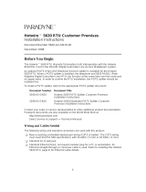
How the NI 5620 Works
A signal follows this path through the NI 5620 to your host computer:
1. The signal enters the NI 5620 through the analog front panel
connector, INPUT. To find more about the front panel, see the
Connecting Signals section later in this chapter.
2. The signal is filtered and conditioned. Gain and dither are applied to
the signal. See the Conditioning the Signal—Impedance, Dither, Gain,
and AC Coupling section for more information.
3. The ADC converts the signal from analog to digital. Refer to the
Digitizing the Signal—The ADC section for more information.
4. (Optional) The digital downconverter (DDC) digitally “zooms in”
on data. See the Incorporating the DDC section.
5. The data is sent to onboard memory (the buffer). See the Storing Data
in Memory section for additional information.
6. The data is transferred to your host computer.
Figure 2-1. Basic Signal Flow
DDC
(Optional)
Filtering/
Conditioning
ADC
Analog
Input
Onboard
Memory
P
X
I
B
u
s

Chapter 2 Hardware Overview
NI 5620 User Manual 2-2 ni.com
Connecting Signals
Figure 2-2 shows the NI 5620 front panel, which contains three
connectors—two SMA connectors and an SMB connector.
One of the SMA connectors, INPUT, is for attaching the analog input signal
you wish to measure. The second SMA connector, REF CLK IN, is a
50 Ω,10 MHz, AC-coupled reference input. The SMB connector, PFI1,
is for external digital triggers.
Figure 2-2. NI 5620 Front Panel
5620
64 MS/s Digitizer
INPUT
50
+20 dBm MAX
REF CLK IN
PFI 1
50
+16 dBm MAX

Chapter 2 Hardware Overview
© National Instruments Corporation 2-3 NI 5620 User Manual
Conditioning the Signal—Impedance, Dither, Gain, and AC Coupling
To minimize distortion, signals receive a minimal amount of conditioning.
There is one set gain, and all signals are AC coupled, meaning that the
NI 5620 rejects any DC portion of a signal. The NI 5620 also has a set input
impedance of 50 Ω and applies dither to the configurable signal.
Input Impedance
The input impedance of the NI 5620 is 50 Ω. The output impedance of the
source connected to the NI 5620 and the input impedance of the NI 5620
form an impedance divider, which attenuates the input signal according to
the following formula:
where V
m
is the measured voltage
V
s
is the unloaded source voltage
R
s
is the output impedance of the external device
R
in
is the input impedance of the NI 5620
If the source whose output you are measuring has an output impedance
other than 50 Ω, your measurements will be affected by this impedance
divider. For example, if the device has 75 Ω output impedance, your
measured signal will be 80% of the value it would have been at 50 Ω.
Dither
Dither is random noise added to the input signal between 0 and 5 MHz.
Dither lowers the amount of distortion caused by differential nonlinearity
in the ADC when a signal is digitized. When an FFT is applied to the signal,
this random noise cancels out most of the distortion created by differential
nonlinearity. Dither is not automatically applied, but you can enable it in
software.
Digitizing the Signal—The ADC
Regardless of your requested sample rate, the NI 5620 ADC is always
running at 64 MS/s. If you request a rate less than 64 MS/s, the timing
engine of the NI 5620 stores only 1 sample in a group of n samples,
effectively reducing the sample rate to 64/n MS/s.
V
m
V
s
R
in
R
in
R
s
+
-------------------
×=

Chapter 2 Hardware Overview
NI 5620 User Manual 2-4 ni.com
Incorporating the DDC
You may optionally route the data through the DDC before storing it in
onboard memory.
The DDC is a digital signal processing (DSP) chip, the Intersil
HSP50214B. The first stage uses a digital quadrature mixer that shifts
a signal to baseband from any frequency within the digitizer’s range.
The next stage decimates (reduces the sample rate) by an integer from 4
to 16384. A series of programmable digital lowpass filters prior to each
stage of decimation prevents aliasing when the sample rate is reduced.
The decimated data may be retrieved as in-phase and quadrature, or as
phase and magnitude. A discriminator allows you to take the derivative
of the phase to demodulate an FM signal.
By mixing, filtering, and decimating the sampled data, the DDC allows
you to zoom in on a band of frequencies much narrower than the Nyquist
band of the ADC. The lower sample rate means that signals of longer
duration can be stored in the same amount of memory. For spectral analysis,
a smaller, faster FFT may be used to look at only the band passed through
the DDC.
Refer to the NI-SCOPE VI Reference Help for specific DDC attributes
you can use to program your NI 5620. If you installed the included
measurement software, there is also online help for LabVIEW users using
the DDC.
Storing Data in Memory
Samples are acquired into onboard memory on the NI 5620 before being
transferred to the host computer. The minimum size for a buffer is
approximately 256 samples, although you can specify smaller buffers in
software. When specifying a smaller buffer size, the minimum number of
points are still acquired into onboard memory, but only the specified
number of points are retrieved into the host computer’s memory.
During the acquisition, samples are stored in a circular buffer that is
continually rewritten until a trigger is received. After the trigger is received,
the NI 5620 continues to acquire posttrigger samples if you have specified
a posttrigger sample count. The acquired samples are placed into onboard
memory. The number of posttrigger or pretrigger samples is limited only by
the amount of onboard memory.

Chapter 2 Hardware Overview
© National Instruments Corporation 2-5 NI 5620 User Manual
Block Diagram
This block diagram is intended for advanced users. An explanation of some
of these features follows.
Figure 2-3. Block Diagram
The digital downconverter is a digital signal processor (DSP) that allows
you to digitally zoom in on data, which reduces the amount of data
transferred into memory and speeds up the rate of data transfer. The digital
downconverter does this by frequency-translating, filtering, and decimating
signals after they go through the ADC. See the Incorporating the DDC
section for more information.
The PLL uses a phase dectetor to synchronize the acquisition clock to
either a 10 MHz reference clock supplied through REF CLK IN or to the
CLK 10 signal from the PXI backplane. You can also choose to leave the
TIO
(Timing and Control)
Digital
Downconverter
Voltage
Controlled
Oscillator
P
X
I
Data Path
Logic
Onboard
Memory
Filter
MITE
(PXI Interface)
ADC
Dither
+
Analog
Input
(INPUT)
Trigger and
Clock Routing
10 MHz
Reference
Input
(REF CLK IN)
EXT TRIG
(PFI)
External Trigger
PXI Trigger
CLK 10
Phase
Detector
CalDAC
PLL

Chapter 2 Hardware Overview
NI 5620 User Manual 2-6 ni.com
acquisition clock in a free-running state, in which the acquisition clock is
not synchronized to any external reference.
The voltage controlled crystal oscillator (VCXO) is a 64 MHz clock.
The trigger and clock routing area directs clock signals and triggers.
The TIO is the timing engine used for the NI 5620.
The MITE is the PXI bus interface. The MITE provides high-speed direct
memory access (DMA) transfers from the NI 5620 to the host computer’s
memory.
Other Features
This section contains information on other features on the NI 5620.
Multiple-Record Acquisitions
After the trigger has been received and the posttrigger samples have
been stored, you can configure the NI 5620 to begin another acquisition
that is stored in another memory record on the device. This process is a
multiple-record acquisition. To perform multiple-record acquisitions,
configure the NI 5620 to the number of records to be acquired before
starting the acquisition. The NI 5620 acquires an additional record each
time a trigger is accepted until all the requested records have been stored
in memory. After the initial setup, this process does not require software
intervention.
Between each record, there is a dead time during which the trigger is not
accepted. If the record length is greater than 80 µs, this dead time will be
500 ns. If, however, the record length is less than 80 µs, the dead time will
be 80 µs. During this time, the memory controller sets up for the next
record. There may also be additional dead time while the minimum number
of pretrigger samples are being acquired. Figure 2-4 shows a timing
diagram of a multiple-record acquisition.

Chapter 2 Hardware Overview
© National Instruments Corporation 2-7 NI 5620 User Manual
Figure 2-4.
Multiple-Record Acquisition Timing Diagram
Triggering
You can externally trigger the NI 5620 through the digital line, PFI1. You
can also use software to trigger it. Figure 2-5 shows the different trigger
sources. The digital triggers are TTL-level signals with a minimum
pulse-width requirement of 100 ns or 16 ns times the DDC decimation.
Figure 2-5. Digital Trigger Sources
Calibration
Although the NI 5620 is factory calibrated, it needs periodic calibration to
verify that it is still within the specified accuracy. For more information on
calibration, contact NI or visit the NI Web site at
ni.com
.
Trigger
Acquisition
In Progress
Buffer
= Trigger Not Accepted (Pretrigger Points Not Acquired)
= Trigger Not Accepted (500 ns Dead Time)
= Trigger Not Accepted (Acquisition in Progress)
= Trigger Accepted
12
1
1 2 3
2
3
500 ns
Trigger
Software
RTSI <0..7>
PFI1
8
PXI Star

Chapter 2 Hardware Overview
NI 5620 User Manual 2-8 ni.com
Synchronizing Multiple PXI Devices
The NI 5620 uses a PLL to synchronize the 64 MHz sample clock to a
10 MHz reference clock. You can either supply the reference clock through
the SMA connector (REF CLK IN) on the front panel or use the system
reference clock on the PXI backplane.
The PXI bus and the NI 5620 have the following timing and triggering
features that you can use for synchronizing multiple digitizers:
• System Reference Clock—Thisisa10MHzclockonthePXI
backplane with ±100 ppm accuracy. It is independently distributed to
each PXI peripheral slot through equal-length traces with a skew of
less than 1 ns between slots. Multiple devices can use this common
timebase for synchronization. This allows each NI 5620 to phase lock
to the system reference clock.
• SMA connector (REF CLK IN)—This is a 10 MHz reference input
that you can use to connect your external frequency source for
synchronization.

© National Instruments Corporation A-1 NI 5620 User Manual
A
Specifications
This appendix lists the specifications of the NI 5620. These specifications
are typical at 25 °C unless otherwise specified.
General Specifications
Number of channels ............................... 1
Resolution .............................................. 14 bits
Max sample rate ..................................... 64 MS/s (also integer
divisions of 64 MS/s)
Onboard memory
Using DDC (complex data) ............ 8 MS
Not using DDC ............................... 16 MS
Input
Signal level
Nominal .......................................... 0 dBm (±0.316 V)
Full-Scale ........................................ +10 dBm (±1.000 V)
Max with dither enabled ................. +9 dBm (±0.891 V)
Max non-operating input level........ +20 dBm (±3.16 V)
Max DC input voltage..................... ±2 V
Input impedance..................................... 50 Ω
Coupling................................................. AC
Fully specified frequency range............. 5 to 25 MHz
Analog bandwidth (–3 dB range)........... 25 kHz to 36 MHz

Appendix A Specifications
NI 5620 User Manual A-2 ni.com
VSWR
0.1 to 25 MHz..................................< 1.5:1
25 to 32 MHz...................................< 3:1
Dither (can be disabled)
Frequency range ..............................15 kHz to 3 MHz
Frequency
Internal Sample Clock
Frequency ........................................64 MHz / n, where 1 ≤ n ≤ 2
32
Accuracy..........................................< ±12 ppm (after calibration)
Noise sidebands
Residual FM ...........................................< 2 Hz
pk–pk
in 10 ms
Amplitude
Average noise density............................. –134 dBm/Hz
Spurious responses (0 dBm signal)
5 to 25 MHz, dither enabled............< –80 dBc
0.1to32MHz,ditherdisabled........–80 dBc
Residual responses (input terminated)....< –85 dBm
Frequency response (5 to 25 MHz)
Relative (to response at 15 MHz) ....Less than ±0.25 dB
Absolute...........................................Less than ±0.5 dB
Absolute, using calibration table .....Less than ±0.1 dB
Absolute (0.1 to 32 MHz)................±2.5 dB
Relative
(0.1 to 32 MHz, to 15 MHz)............±1.5 dB
Offset Density
100 Hz < –100 dBc/Hz
1kHz < –120 dBc/Hz
10 kHz < –130 dBc/Hz
100 kHz < –130 dBc/Hz
/