Page is loading ...

P/2 DA2xi MT • User Guide
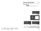
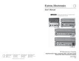
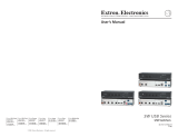
The Extron P/2 DA2xi MT is a distribution amplier that accepts video input from a VGA, XGA, UXGA, or QXGA compatible PC
and distributes the signal to separately buffered outputs. The output on the back of the unit can be extended with Extron VGA
Series cables from 6 feet to 250 feet in length. The MT model also has audio input and output.
FCC Class A Notice
This equipment has been tested and found to comply with the limits for a Class A digital device, pursuant to part 15 of the
FCC rules. The Class A limits provide reasonable protection against harmful interference when the equipment is operated in a
commercial environment. This equipment generates, uses, and can radiate radio frequency energy and, if not installed and used
in accordance with the instruction manual, may cause harmful interference to radio communications. Operation of this equipment
in a residential area is likely to cause interference; the user must correct the interference at his own expense.
Specifications Availability
Product specications are available on the Extron website, www.extron.com.
Features
• Power and Signal LED — Green LED = power + signal. Amber LED = power but no signal. Off = no power.
• Gain and Peak DIP switch — Use this feature to compensate for longer cable runs.
• Out Imp DIP switch — Changes the output impedance to be compatible with all projectors.
• Cable retention chain — The input cable can be secured to the unit with the supplied chain (attached to the right standoff
nut of the input VGA connector) to prevent the cable from being lost or misplaced.
MONITOR
AUDIO
INPUT
Figure 1. P/2 DA2xi MT Distribution Amplifier
Connectors, Indicators, and Controls
The front and rear panels of the P/2 DA2xi MT are described on the following pages.
AUDIO
INPUT MONITOR
LR
P/2 DA2xi MT
OUTPUT
1
ON
2
EXT POWER (see manual)
12V
0.2A MAX
GAIN/PEAK
OUT IMP
1
23 4
6
7
7
8
8
5
9
Figure 2. Front and Rear Panels
1
Power and Signal indicator LED
2
Audio input connector
3
Video input connector
4
Monitor connector
5
Power connector
6
Two-bank DIP switches
7
Video output connector
8
Audio output connector
9
Local monitor cable assembly
1
2
1

1
Power and Signal indicator LED — (see figure2 on the previous page) When lit green, this LED indicates that the
distribution amplifier is receiving both power and a computer signal. When lit amber, it indicates that the distribution amplifier
is receiving power but no computer signal.
2
Audio input connector — Plug a 3.5mm, mini plug audio cable from the sound card of a computer into this jack.
3
Video input connector — Connect the VGA-QXGA output of a computer to this connector.
4
Monitor connector — Connect a local monitor to this connector.
5
Power connector — Plug the external 12 V power
Power Supply
Output Cord
Captive Screw
Connector
3
5
SECTION A–A
Ridges
Smooth
AA
Tie Wrap
only when needed (see
1
, Power and Signal indicator
LED above), into this 2-pole captive screw connector.
The included power supply is shipped with a plug
installed. If you need to cut the DC output cord to a
different length and reinstall the plug, refer to the
following figure and notes.
Figure 3. Power Connector Wiring
ATTENTION: Potential Damage to Property:
ATTENTION : Possibles dégâts matériels :
• If not provided with a power supply, this product is intended to be supplied by a UL Listed power source marked
“Class 2” or “LPS” and rated output 12V dc, min 0.5 A.
• Si le produit n’est pas fourni avec une source d’alimentation, il doit être alimenté par une source d’alimentation
certifiée UL de classe 2 ou LPS, avec une tension nominale 12 Vcc, 0.5 A minimum.
• Always use a power supply provided by or specified by Extron. Use of an unauthorized power supply voids all
regulatory compliance certification and may cause damage to the supply and the end product.
• Utilisez toujours une source d’alimentation fournie ou recommandée par Extron. L’utilisation d’une source
d’alimentation non autorisée annule toute certification de conformité réglementaire, et peut endommager la source
d’alimentation et l’unité.
• Unless otherwise stated, the AC/DC adapters are not suitable for use in air handling spaces or in wall cavities.
The power supply is to be located within the same vicinity as the Extron AV processing equipment in an ordinary
location, Pollution Degree 2, secured to the equipment rack within the dedicated closet, podium or desk.
• Sauf mention contraire, les adaptateurs CA/CC ne conviennent pas à une utilisation dans les espaces d’aération
ou dans les cavités murales. La source d’alimentation doit être placée à proximité de l’équipement Extron dans un
emplacement ordinaire soumis à un degré de pollution de catégorie II, solidement fixé au rack d’équipement d’une
baie technique, d’un pupitre, ou d’un bureau.
• The installation must always be in accordance with the applicable provisions of National Electrical Code ANSI/NFPA
70, article 75 and the Canadian Electrical Code part 1, section 16. The power supply shall not be permanently fixed
to building structure or similar structure.
• L’installation doit toujours être conforme aux dispositions applicables du Code américain de l’électricité (National
Electrical Code) ANSI/NFPA 70, article 725, et du Code canadien de l’électricité. La source d’alimentation ne devra
pas être fixée de façon permanente à la structure de bâtiment ou à d’autres structures similaires.
• When you connect the power supply, voltage polarity is extremely important. Applying power with incorrect voltage
polarity could damage the power supply and the amplifier. Identify the power cord negative lead by the ridges on the
side of the cord.
• Lorsque vous connectez la source d’alimentation, la polarité de la tension est extrêmement importante. Une
alimentation avec une polarité de tension incorrecte peut endommager la source d’alimentation ainsi que l’interface.
Il est essentiel d’identifier une connexion négative du cordon d’alimentation au niveau des stries sur les parties
latérales du cordon.
NOTE: Do not tin the stripped power supply leads before installing the captive screw connector. Tinned wires are not as
secure in the connectors and could pull out. Strip the power cord jacket 5 mm from the end.
2
P/2 DA2xi MT • User Guide (Continued)

CAUTION: Risk of Electric Shock
The two power cord wires must be kept separate while the power supply is plugged in. Remove power before
continuing.
ATTENTION : Risque de choc électrique
Les deux cordons d’alimentation doivent être maintenus à l’écart tant que la source d’alimentation est branchée. Avant
de continuer, coupez l’alimentation.
To verify the polarity before connection, plug in the power supply with no load and check the output with a voltmeter.
6
Two-bank DIP switches — (see figure2 on page1) These switches affect only the video output (
7
), not the monitor
output (
4
). The Gain/Peak DIP switch should be on (up) when the output cable is over 100 feet (30.5 m). The Out Imp DIP
switch changes output impedance. If all connections and operations are correct, but the output device has no picture, switch to
the other position.
7
Video output connector — Connect the video output device (projector, display panel, or monitor) to this connector.
8
Audio output connector — Wire a 3.5mm 5-pole captive screw audio connector as shown below, and plug it into this
connector. Connect the other end of the cable to an audio output device or recorder.
Do not tin the wires!
Unbalanced Stereo Output Balanced Stereo Output
Ring
Sleeve(s)
Tip
Tip
Ring
Sleeve(s)
Tip
Tip
NO GROUND HERE.
NO GROUND HERE.
LR
LR
ATTENTION: Potential Damage to Property.
Connect the sleeve to ground (Gnd). Connecting the sleeve to a negative (-) terminal will damage the audio output
circuits.
ATTENTION : Possibles dégâts matériels :
Connectez le manchon à la borne de terre (Gnd). Connecter le manchon à une borne négative(-) endommagera les circuits
de la sortie audio.
9
Local monitor cable assembly — Use this cable assembly to connect the local monitor (video) and speaker (audio) to
the unit. The chain is used to attach the cable to the unit, to prevent the cable from being lost or misplaced.
Mounting
WARNING: Potential risk of serious injury.
Installation and service must be performed by authorized personnel only. This product should be used with a UL approved
electrical box.
AVERTISSEMENT : Risque potentiel de blessure grave ou de mort:
L’installation et l’entretien doivent être effectués uniquement par un technicien qualié. Ce produit devrait être utilisé avec un
boîtier électrique certié UL.
The P/2 DA2xi MT can be mounted on a rack shelf, under a desk or tabletop, or on a projector bracket.
UL Rack Mounting Guidelines
The following Underwriters Laboratories (UL) guidelines pertain to the safe installation of the equipment in a rack.
1. Elevated operating ambient temperature — If installed in a closed or multi-unit rack assembly, the operating ambient
temperature of the rack environment may be greater than room ambient temperature. Therefore, install the unit in an
environment compatible with the maximum ambient temperature (Tma = +122 °F, +50 °C) specified by Extron.
2. Reduced air flow — Install the equipment in a rack so that the amount of air flow required for safe operation of the
equipment is not compromised.
3. Mechanical loading — Mount the equipment in the rack so that a hazardous condition is not achieved due to uneven
mechanical loading.
4. Circuit overloading — Connect the equipment to the supply circuit and consider the effect that circuit overloading might
have on overcurrent protection and supply wiring. Appropriate consideration of equipment nameplate ratings should be used
when addressing this concern.
5. Reliable earthing (grounding) — Maintain reliable grounding of rack-mounted equipment. Pay particular attention to supply
connections other than direct connections to the branch circuit (that is, use of power strips).
3

© 2003-2019 Extron Electronics — All rights reserved. www.extron.com
All trademarks mentioned are the property of their respective owners.
Worldwide Headquarters: Extron USA West, 1025 E. Ball Road, Anaheim, CA 92805, 800.633.9876
For information on safety guidelines, regulatory compliances, EMI/EMF compatibility, accessibility, and related topics, see the
Extron Safety and Regulatory Compliance Guide on the Extron website.
Rack Mounting
For optional rack mounting, mount the P/2DA2xiMT on a 19-inch 1U rack shelf kit, a universal 1U 6-inch deep rack shelf kit, or a
universal 1U 9.5-inch deep rack shelf kit (see gure 4).
1. Remove the rubber feet (if installed) and mount the unit on the rack shelf, using two screws in opposite (diagonal) corners.
2. Install blank panels or other units to the rack shelf, as required.
3. Insert the shelf into the rack, and secure the shelf to the rack using the supplied machine screws.
Use 2 mounting holes
on opposite corners.
(2) 4-40 x 3/16"
Screws
1U Universal Rack Shelf
Both front false faceplates
use 2 screws.
1/4 Rack Width
False Faceplate
1/2 Rack Width
False Faceplate
(2) 4-40 x
3/16" Screws
Use 2 mounting holes
on opposite corners.
1/4 Rack Width
False Faceplate
Rack Shelf for
3.5" Deep Products
Figure 4. Rack Mounting Options
Furniture Mounting
For optional furniture mounting, mount the unit using an under-desk
mounting kit:
1. Attach the mounting brackets to the distribution amplifier
INPUT
MONITOR
with the provided machine screws, as shown below.
2. If feet were previously installed on the bottom of the unit,
remove them.
3. Hold the unit with the attached brackets against the underside
of the table or other furniture. Mark the location of the screw
holes of the bracket on the mounting surface.
4. Drill 3/32 inch (2 mm) diameter pilot holes, 1/4 inch (6.3 mm)
deep in the mounting surface at the marked screw locations.
5. Insert #8 wood screws into the four pilot holes. Tighten each
screw into the mounting surface until just less than 1/4 inch
of the screw head protrudes.
6. Align the mounting screws with the slots in the brackets and
place the unit against the surface, with the screws through the
bracket slots.
7. Slide the unit slightly forward or back, then tighten all four
screws to secure the unit in place.
Figure 5. Furniture Mounting Option
4
68-713-01 Rev. H
05 19
/