
Operator’s Manual
Auto Mower
Please read the Operator’s Manual carefully and make sure you
understand the instructions before using the machine
EE
EE
nn
nn
gg
gg
ll
ll
ii
ii
ss
ss
hh
hh

English-
3
Operator’s Manual for
Auto Mower
Contents
Auto Mower Helpdesk
Telephone number: 020 - 77 77 22
Monday - Friday: 8.00 - 20.00
Saturday - Sunday: 12.00 - 16.00
Introduction ................................................ 4
Congratulations .........................................4
Symbols ...................................................... 5
Symbols on Auto Mower ..........................5
Symbols in the Operator’s Manual ............6
Safety instructions...................................... 7
Use ...........................................................7
Transport...................................................8
Maintenance .............................................8
Presentation ................................................ 9
Function Auto Mower ..............................10
Capacity .................................................12
Installation .................................................13
A. Preparations ......................................13
Auto Mower, what is what? ....................14
B. Planning the installation .....................15
C. Placement of the charging station .....20
D. Charging the battery ..........................22
E. Laying out the boundary wire .............22
F. Connecting the boundary wire ...........23
G. Checking the installation ...................25
H. Linking the Auto Mower to the charging
station......................................................25
Control panel .............................................26
Shortcuts .................................................27
Program ................................................27
Section ...................................................28
Numbers .................................................28
Main switch ............................................28
Menu functions ..........................................29
Main menu .............................................29
1. Commands ......................................... 30
2. Timer ..................................................30
3. Installation ..........................................32
4. Settings ..............................................35
Use .............................................................40
Charging a discharged battery ...............40
Starting the Auto Mower ........................40
Using the timer .......................................41
Stopping the Auto Mower .......................41
Restart ...................................................41
Turning off the Auto Mower ....................41
Adjusting the cutting height ....................42
Maintenance ..............................................43
Battery ....................................................43
Winter Storage .......................................43
Cleaning .................................................44
Replacing the blade units .......................45
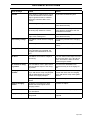
Trouble shooting ......................................46
Fault messages ...................................... 46
Trouble shooting chart ............................48
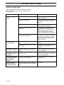
Technical data............................................49
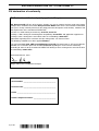
EU declaration of conformity....................50

English-
4
INTRODUCTION
Introduction
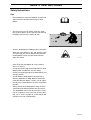
Congratulations
Thank you for purchasing a Husqvarna Auto Mower. The Husqvarna Auto Mower is designed to offer user
friendliness, high operating safety and a long service life. Auto Mower has been built to mow areas that
contain slopes and confined passages as well as many trees and bushes. Using only a minimum of
supervision and maintenance you can have a well-kept lawn throughout the season.
This Operator’s Manual is a valuable document. By following its contents (use, maintenance, etc) you can
contribute towards a long life for the mower and enhance its trade-in value. Read through the Operator's
Manual carefully before you start to install and use your Auto Mower.
Save the Operator’s Manual and, if you sell your Auto Mower, make sure you hand it over to the new owner.
Husqvarna Auto Mower is designed to mow the grass on ordinary lawns free from stones, large branches
and the like. All other types of use are incorrect. The manufacturer’s instructions with regard to driving,
maintenance, and repair must be followed precisely.
WARNING!
Under no circumstances may the original design of the Auto Mower be modified
without the expressed permission of the manufacturer.
Unauthorized modifications and/or components can result in serious disruptions
and the risk of personal injuries.
Always use original spare parts.

English-
5
SYMBOLS
Symbols
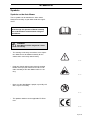
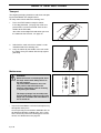
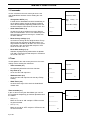
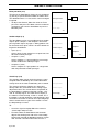
Symbols on the Auto Mower
These symbols can be found on the lawn mower.
Study them carefully so you understand their signifi-
cance.
• The warnings and safety instructions in the Opera-
tor’s Manual must be followed carefully for the
mower to be used safely and efficiently.
• Keep your hands and feet away from the rotating
blades. Never put your hands or feet close to or
under the body of the Auto Mower while it is run-
ning.
• Never use the Auto Mower if people, especially chil-
dren, or pets are nearby.
• This product conforms to the applicable EU Direc-
tives.
IMPORTANT INFORMATION
Read through the Operator’s Manual carefully
and understand the content before using the
Auto Mower.
1001-003
WARNING
Auto Mower can be dangerous if used
incorrectly.
1001-002
3012-274
3012-273
6001-024

English-
6
SYMBOLS
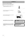
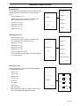
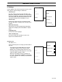
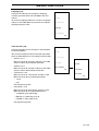
Symbols in the Operator’s Manual
These symbols can be found in the Operator’s Manual.
Study them carefully so you understand their signifi-
cance.
• Inspection and/or maintenance should be carried
out with the main switch set to ”OFF”.
• Always wear protective gloves when working with
the mower’s underframe.
• Never use a high-pressure washer or even running
water to clean the Auto Mower.
• The warning box warns of the risk of
personal
injury
, especially if the instructions are not followed.
• The information box indicates the risk of
material
damage
, especially if the instructions are not fol-
lowed. The box is also used where there is a risk of
user error.
3012-288
OFF
3012-272
3012-271
WARNING
Xxxx xxxxx xxxx xxxx xxx xxx.
Xxxx xxxxx xxxx xxx xxx xxxx.
IMPORTANT INFORMATION
Xxxxxx xxx xxxx xxxxxxx xxx
xxxx xxxx xxxxx xxx.

English-
7
SAFETY INSTRUCTIONS
Safety Instructions
Use
• Read through the Operator’s Manual carefully and
understand the content before using the Auto
Mower.
• Check that there are no stones, branches, tools,
toys or other objects on the lawn that can damage
the blades and cause the mower to stop.
• Start the Auto Mower according to the instructions.
When the main switch is in the ”ON” position; make
sure you keep your hands and feet away from the
rotating blades. Never put your hands and feet
under the mower.
• Never lift up the Auto Mower or carry it around
when it is running.
• Do not let persons who do not know how the Auto
Mower works and behaves use the mower.
• Do not put anything on top of the Auto Mower or its
charging station.
• Do not allow the Auto Mower to be used with a
defective blade disc or body. Neither should it be
used with defective blades, screws, nuts or cables.
• Do not use the Auto Mower if the main switch does
not work.
• Always switch off the Auto Mower using the main
switch when you do not intend to use the mower.
• The Auto Mower must never be used at the same
time as a sprinkler. In this case use the timer func-
tion, see ”2. Timer” on page 30, so the mower and
sprinkler never run simultaneously.
1001-003
3012-275
3012-274

English-
8
SAFETY INSTRUCTIONS
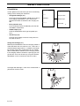
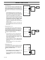
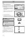
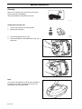
Transport
The original packaging should be used when transport-
ing the Auto Mower over long distances.
To safely move from or within the working area:
1. Press the STOP button to stop the mower.
If the stop protection, (see page 36) used as to
prevent theft, has been activated enter the first
number of the PIN-code.
You select the four digit PIN code when you start
the mower for the first time, see page 25.
2. Switch off the main switch if the mower is to be
moved outside of the working area.
3. Carry the mower by the handle at the rear under
the mower. Carry the mower with the top against
your body.
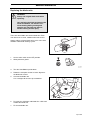
Maintenance
• Inspect the Auto Mower each week and replace any
damaged or worn parts.
Check especially that the blades and blade disc are
not damaged. Replace all blade units at the same
time if necessary so that the rotating parts are bal-
anced, see ”Maintenance” on page 43.
3012-247
3012-261
3012-250
ON
OFF
WARNING
When the mower is turned upside down
the main switch must always be set to
the OFF position.
The main switch should be set to the
OFF position with all work on the
mower’s underframe, such as cleaning
or replacing the blades.
The beeps (5 beeps in 5 seconds) warn
that the blade disc is about to start, if the
beeps are not audible the Auto Mower is
set to sound off.

English-
9
PRESENTATION
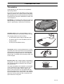
Presentation
Congratulations on your choice of an exceptionally
high quality product.
To get the best from your Auto Mower requires knowl-
edge of its function. This chapter contains information
you should be aware of when planning the installation.
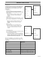
Installation of the Husqvarna Auto Mower includes four
main components:
Auto Mower
, an automatic lawn mower that mows the
lawn by moving in essentially an irregular pattern. The
mower is powered by a maintenance free battery
Charging station
, where your Auto Mower returns
when the charge level in the battery becomes too low.
The charging station has three functions:
• To send control signals along the boundary wire.
• To send out signals so the Auto Mower finds the
charging station.
• To charge the Auto Mower battery.
Transformer
, which is connected between the charg-
ing station and a 230 V wall socket. The transformer is
connected to the wall socket via an integrated power
cord and to the charging station via a 20 m long low
voltage cable. The length of the low voltage cable must
not be changed.
Boundary wire
, laid in a loop around the Auto Mower’s
working area. The wire is laid around the edges of the
lawn and around objects and plants that the mower
must not run into.
The length of boundary wire needed in an installation
is the circumference of the working area plus a few
extra metres to lay around ”islands”, objects and
plants. A few extra metres are also required for any
subsequent adjustments. The boundary wire supplied
for the installation is 250 m long. If this is not sufficient
more wire can be purchased, with a connector, and
spliced onto the existing wire.
3012-278
3012-216
3012-220
3012-221

English-
10
PRESENTATION
Function Auto Mower
Working method
The Auto Mower automatically mows the lawn. It con-
tinuously combines mowing and charging.
When the Auto Mower works on a lawn, it simulta-
neously stores information about how the garden is
shaped.
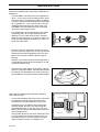
The charging station sends out a signal that the Auto
Mower can sense at a distance of 6 - 8 metres. The
mower starts to seek out the charging station when the
capacity of the battery becomes too low. The Auto
Mower does not mow when it is searching for the
charging station.
When the battery is charged the mower reverses, turns
around and leaves the charging station in a randomly
selected direction within the exit sector 90°-270°. Both
the reversing length and exit direction can be set, see
”3. Installation” on page 32.
When the Auto Mower body hits an obstacle, the
mower reverses and selects a new direction.
Two sensors, front and back on the Auto Mower, sense
when the mower approaches the boundary wire. The
Auto Mower overruns the wire by up to 27 centimetres
before it turns. The overrun length can be set, see
”Drive past wire (3-2)” on page 34.
3012-233
3012-225
3012-226

English-
11
PRESENTATION
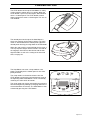
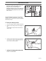
The STOP button on the top of Auto Mower is mainly
used to stop the mower when it’s running. When the
STOP button is pressed a cover opens, behind which
there is a control panel. The STOP button remains
depressed until the cover is closed again. This acts as
start inhibitor.
The control panel on the top of the Auto Mower is
where you manage all the mower settings. The main
switch is also located on the control panel. Open the
control panel cover by pressing down the STOP button.
When the main switch is turned ON for the first time, a
start-up sequence begins which includes: selection of
the language, time format, date format and the four
digit PIN code as well as the setting of the time and
date, see page 25.
The Auto Mower can enter a sleep mode to save
power. The display on the control panel is then com-
pletely dimmed.
The sleep mode is activated 25 minutes after the
STOP button has been pressed and then not reset to
the operating mode. Auto Mower is then activated by
switching the main switch off and on.
The sleep mode can also be activated in the event of a
fault occurring during mowing or charging and which is
not rectified within 25 minutes. The Auto Mower is then
activated by pressing the STOP button.
3012-247
3012-283
3012-297

English-
12
PRESENTATION
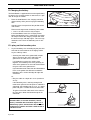
Movement pattern
The mower’s movement pattern is irregular and is
determined by the Auto Mower itself. A movement pat-
tern is never repeated. This mowing system means the
lawn is mown equally without any mowing lines.
If the Auto Mower enters an area where it senses the
grass is longer than earlier, it can change the move-
ment pattern. It can then mow in a square pattern to
cover the area of longer grass more systematically.
Thereafter the mower returns to the irregular move-
ment pattern.
Capacity
The Auto Mower is recommended for lawns up to
1800 m
2
.
Auto Mower mows about 75 m
2
per hour. How large an
area is mown depends primarily on the condition of the
blades and the type of grass, growth rate and humidity.
The shape of the garden is also significant. If the gar-
den mainly consists of open lawns, the Auto Mower
can mow more per hour than if the garden consists of
several small lawns separated by many trees, flower
beds and passages.
How long the Auto Mower mows respective charges
can vary depending on, among others, the ambient
temperature. Up to about 25°C a fully charged Auto
Mower mows for approximately 60 - 90 minutes,
depending on the age of the battery and the thickness
of the grass. The mower then charges for about 60
minutes. Above 25°C both the mowing and charging
times gradually drop.
3012-276
3012-277

English-
13
INSTALLATION
Installation
This chapter describes how you install the Auto Mower.
Before starting the installation read the previous chap-
ter ”Presentation” on page 9 to page 12.
The installation should be carried out according to
the following steps:
A. Preparations.
B. Planning the installation
C. Placing the charging station.
D. Charging the battery.
E. Laying the boundary wire.
F. Connecting the boundary wire.
G. Checking the installation
H. Linking the Auto Mower to the charging station.
The letters refer to the following headings.
A. Preparations
1. If the lawn in the working area is longer than 15
cm mow it using a conventional lawn mower. Then
collect the clippings.
2. Read carefully through all steps before the instal-
lation.
3. Check that all parts for the installation are
included:
The numbers in brackets refer to the detail dia-
gram ”Auto Mower, what is what?” on page 14.
• Operator’s Manual (22)
• Auto Mower
• Charging station (14)
• Boundary wire in the right length (16)
• Transformer (17)
• Low voltage cable (18)
• Staples (19)
• Boundary wire connector (20)
• Boundary wire coupler (21)
During installation you will also need:
• Combination pliers
• Straight spade, if the boundary wire is to be bur-
ied
3012-301

English-
14
INSTALLATION
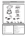
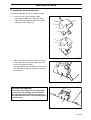
Auto Mower, what is what?
The numbers in the picture corresponds to:
1. Charging strip
2. Cutting height adjustment cover
3. Front wheel
4. Drive wheel
5. Body
6. Stop button
7. Keypad
8. Display
9. Main switch
10. Handle
11. Chassis box with electronics, battery and
motors
12. Skid plate
13. Blade disc
14. Charging station
15. LED for operation check of the boundary wire
16. Boundary wire
17. Transformer with power cord
18. Low voltage cable
19. Staples
20. Boundary wire connector
21. Boundary wire coupler
22. Operator’s Manual
1
2
3
4
5
6
7
8
9
10
11
12
13
14
15
16
17
18
19 20
21
22
6
3012-224

English-
15
INSTALLATION
B. Planning the installation
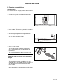
Charging station
First and foremost the charging station should be posi-
tioned:
• Centrally in the main area, along the outer edge
and with a large free area in front of the station.
• In the shadow. The battery is spared if it charged in
the low possible ambient temperature.
• On relatively level ground. The height difference
must not differ more than 10 cm between the front
and rear of the charging station.
• Close to a wall socket:
The charging station should be connected to a
230 V wall socket via the low voltage cable and
transformer.
The supplied low voltage cable is 20 metres long.
The transformer must be placed where it is well
ventilated and is not exposed to direct sunlight. It is
also beneficial if the transformer can be placed
under a roof.
It is recommended to use an earth fault-breaker
when connecting the transformer to the wall socket.
3012-233
3012-296
Max 10 cm
Max 10 cm
3012-220
3012-223
IMPORTANT INFORMATION
The length of the low voltage cable must not be
changed.

English-
16
INSTALLATION
Plan the position of the charging station according to
the shape of your garden.
The Auto Mower can be set for one of three basic gar-
den shapes (see page 34).
The Auto Mower works differently depending on the
garden shape the mower has been set to.
The available garden shapes are: open, complex 1 and
complex 2.
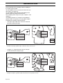
The following pictures are examples of the different
garden shapes. The pictures are also good examples
of appropriate charging station placement.
• The open shape represents a lawn area with few
obstacles and no passages.
• Complex 1 is a large lawn area with an average
amount of obstacles and passages.
3012-290
3012-291
Example of the open garden shape. Lawn area 400 m
2
and 1100 m
2
2,5
3012-292
3012-293
Example of complex 1 garden shape. Lawn area 900 m
2
respective 1000 m
2
2,5

English-
17
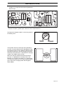
INSTALLATION
• Complex 2 is a large lawn area with many obstacles
and passages.
Do not put the charging station in a corner or pocket in
the working area.
If the garden consists of two large lawns joined by a
passage, it may be difficult for the Auto Mower to find
the entrance to the passage. Making it difficult to work
efficiently in both areas. One way to make the mower
effectively reach both areas is to position the charging
station in the middle of the passage.
When the charging station needs to be placed in a
passage, is it appropriate to manually set the exit
direction, see ”Charge exit settings (3-1)” on page 32.
This will ensure both areas are mown equally and the
grass close to the charging station will not appear
down trodden.
3012-294
3012-295
Example of complex 2 garden shape. Lawn area 1500 m
2
respective 800 m
2
3012-235
3012-237

English-
18
INSTALLATION
Boundary wire
For a successful installation the placement of the
boundary wire should be planned carefully. Planning is
simplified if you make a sketch of the working area,
including all obstacles. Draw how the boundary wire
should be routed on the sketch.
The boundary wire should be laid so it:
• Forms a loop around the working area for the Auto
Mower. Only Husqvarna boundary wire ought to be
used. This is tinned and has a high quality insulation
to withstand the dampness in the ground.
• Is a maximum of 500 metres long.
• Maintains a maximum distance of 35 metres from
Auto Mower in the entire working area.
• Does not lie on a sharp incline. The Auto Mower
may find it difficult to reverse back, especially in
damp weather conditions, when there is a large risk
of skidding.
Include the possibility in the planning that adjustments
may need to be made to the loop. In doing so remem-
ber:
• Leave a few extra metres of wire at the beginning
and end, close to the charging station.
• Place a few extra metres of wire about every 30
metres around the entire loop.
All extra wire should be laid in tight, parallel loops If
staples are used, the parallel loops should be
placed under the same staple.
3012-138
IMPORTANT INFORMATION
Extra wire must not be placed in coils outside
the boundary wire. This can disrupt the Auto
Mower.
3012-281

English-
19
INSTALLATION
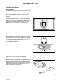
Remember the following with regard to the working
area boundaries:
• If a high obstacle, for example a wall or fence, bor-
ders the working area, the boundary wire should be
laid 35 cm from the obstacle. This will prevent the
Auto Mower from colliding with the obstacle and
reduce body wear.
• If the working area borders against, for example,
pools of water the boundary wire should be supple-
mented with a fence or the like. The height must
then be at least 10 cm. This will prevent the Auto
Mower, under any circumstances, coming outside
of the working area.
• If the working area borders against a small ditch, for
example, a flower bed or a small elevation, e.g. a
low verge (3-5 cm), the boundary wire should be
laid 30 cm inside the working area. This prevents
the wheels from driving into the ditch or up onto the
verge.
• If the working area borders against a flat path or the
like that lies level with the lawn, is it possible to
allow the Auto Mower to run a little over the path.
The boundary wire should then be laid 10 cm from
the edge of the path.
35 cm
3012-229
30cm
3012-228
10 cm
3012-230

English-
20
INSTALLATION
Remeber the following with regard to the working area
boundaries:
• The Auto Mower can mow areas with a gradient of
up to 1: 3 (33 cm/m) inside the working area. Areas
that slope more must be demarcated by the bound-
ary wire. If any part of the working area’s outer edge
has a gradient of 1: 5 (20 cm/m) or more, the wire
should be laid inside where the slope starts. The
Auto Mower may find it difficult to turn at the loop
where the ground slopes heavily.
• Use the boundary wire to demarcate areas inside
the working area, for example, flower beds and
fountains. Lay the cable up to the area, around it
and then return along the same route. If staples are
used, the cable should be laid under the same sta-
ple on the return route.
• Obstacles that can withstand a collision, for exam-
ple, trees or bushes higher than 10 cm, do not need
to be demarcated by the boundary wire. The Auto
Mower will turn when it collides with this type of
obstacle.
However, for the most gentle and silent operation, it
is preferable to demarcatee all fixed objects in and
around the working area.
• Obstacles that slope slightly, for example, stones or
large trees with raised roots, should be demarcated
or removed. The Auto Mower can slide up onto this
kind of obstacle causing the blades to be damaged.
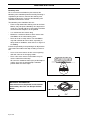
Remember the following with regard to secondary
areas and passages:
• If there are secondary areas close to the main area
the boundary wire should be laid so that these
areas form an ”island” outside of the main area.
Secondary areas are working areas without the
charging station, but which are encircled by the
same boundary wire as the main area. The Auto
Mower must be moved manually between the main
and secondary areas.
If the garden consists of two areas where one area
is much smaller than the other and the areas are
only connected by a very long narrow passage, it
may be suitable to create a secondary area.
3012-108
Minimise
3012-231
3012-279
Secondary area
Main area

English-21
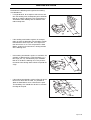
INSTALLATION
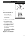
• In order for the loop system to work well, the wires
in passages where the Auto Mower is to run
through must not lie too close together.
A passage should be at least 2 metres wide so the
Auto Mower can find it and make its way through it.
The minimum spacing between the wires in a pas-
sage is 130 cm.
The transition between a large area and a passage
should be, if possible, designed like a ”funnel”, with
rounded corners, to make it easier for the Auto Mower
to enter the passage.
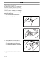
C. Placing the charging station
1. Place the charging station according to your plan.
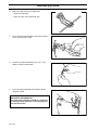
2. Connect the low voltage cable to the charging sta-
tion.
Only Husqvarna original cable and transformer
may be used.
3. Connect the low voltage cable to the transformer.
The connectors may be a slightly difficult to con-
nect, as they are moisture-proof.
4. Connect the transformer’s power cord to a 230V
wall socket. It is preferable to use an earth-fault
breaker as recommended.
Secondary
area
Main area
2m
3012-232
3012-263
3012-262
Page is loading ...
Page is loading ...
Page is loading ...
Page is loading ...
Page is loading ...
Page is loading ...
Page is loading ...
Page is loading ...
Page is loading ...
Page is loading ...
Page is loading ...
Page is loading ...
Page is loading ...
Page is loading ...
Page is loading ...
Page is loading ...
Page is loading ...
Page is loading ...
Page is loading ...
Page is loading ...
Page is loading ...
Page is loading ...
Page is loading ...
Page is loading ...
Page is loading ...
Page is loading ...
Page is loading ...
Page is loading ...
Page is loading ...
Page is loading ...
-
 1
1
-
 2
2
-
 3
3
-
 4
4
-
 5
5
-
 6
6
-
 7
7
-
 8
8
-
 9
9
-
 10
10
-
 11
11
-
 12
12
-
 13
13
-
 14
14
-
 15
15
-
 16
16
-
 17
17
-
 18
18
-
 19
19
-
 20
20
-
 21
21
-
 22
22
-
 23
23
-
 24
24
-
 25
25
-
 26
26
-
 27
27
-
 28
28
-
 29
29
-
 30
30
-
 31
31
-
 32
32
-
 33
33
-
 34
34
-
 35
35
-
 36
36
-
 37
37
-
 38
38
-
 39
39
-
 40
40
-
 41
41
-
 42
42
-
 43
43
-
 44
44
-
 45
45
-
 46
46
-
 47
47
-
 48
48
-
 49
49
-
 50
50


Ask a question and I''ll find the answer in the document
Finding information in a document is now easier with AI
Related papers
-
Husqvarna Robotic Lawn Mower User manual
-
-
Husqvarna AUTOMOWER 310 Owner's manual
-
-
-
-
-
-
-
Other documents
-
 POINT PORLMW1 ROBOTGRESSKLIPPER User manual
-
Robomow RC306 (Up to 1/8 Acre) FAQ
-
-
-
Gardena R45Li Installation guide
-
Yard Force SA500ECO Owner's manual
-
 High Tech Pet YS-50 User guide
-
-
McCulloch 967059805 Installation guide
-

