Emerson THROUGH 1200 User manual
- Category
- Power generators
- Type
- User manual
This manual is also suitable for
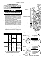
Emerson THROUGH 1200 is an automatic transfer switch designed to seamlessly transition between normal and emergency power sources. It features a compact design, making it suitable for various applications, including data centers, hospitals, and industrial facilities. The device ensures uninterrupted power supply, enhancing reliability and minimizing downtime during power outages.
Emerson THROUGH 1200 is an automatic transfer switch designed to seamlessly transition between normal and emergency power sources. It features a compact design, making it suitable for various applications, including data centers, hospitals, and industrial facilities. The device ensures uninterrupted power supply, enhancing reliability and minimizing downtime during power outages.


-
 1
1
-
 2
2
-
 3
3
-
 4
4
-
 5
5
-
 6
6
-
 7
7
-
 8
8
-
 9
9
-
 10
10
-
 11
11


Emerson THROUGH 1200 User manual
- Category
- Power generators
- Type
- User manual
- This manual is also suitable for
Emerson THROUGH 1200 is an automatic transfer switch designed to seamlessly transition between normal and emergency power sources. It features a compact design, making it suitable for various applications, including data centers, hospitals, and industrial facilities. The device ensures uninterrupted power supply, enhancing reliability and minimizing downtime during power outages.
Ask a question and I''ll find the answer in the document
Finding information in a document is now easier with AI
Related papers
Other documents
-
Trendnet Series 300 User manual
-
Simplicity 071112 User manual
-
Simplicity 071098 User manual
-
-
Infocus Switch 165 User manual
-
Schneider Electric 300 Series User manual
-
GE General Electric Switch ZTSCT User manual
-
ABB Zenith MX250 Operation and Maintenance Manual
-
-
Asco 300 Series Power Panels Installation guide