Page is loading ...

Satellite Television
KVHTracVision
®
6
technical
manual
•
Installation
•
Configuration
•
Maintenance
A Guide to TracVision 6

1
54-0166 Addendum to Rev. C
TracVision 6-HP
Technical Manual Addendum
(ECO #7134)
The following changes apply to Revision C of the
TracVision 6-HP Technical Manual (KVH Part Number 54-0166).
The “=TV” configuration command printed in the manual is incorrect.
For your TracVision 6-HP system, the correct configuration command
is
=TVG6HPT
, not
=TVG6HP
.
You will need to enter the
=TVG6HPT
command whenever you replace
the main printed circuit board (PCB) or calibrate the antenna gyro, at
the steps noted below.
4.4 Replacing the PCBs and Fuses
Replacing the Main PCB
13. Type =TVG6HPT<cr> (<cr> = Press the Enter key).
4.5 Replacing the Antenna Gyro
Assembly
Calibrating the Antenna Gyro
8. Type =TVG6HPT<cr>.

TracVision 6
Technical Manual
This manual provides detailed instructions on the proper
installation, configuration, troubleshooting, and maintenance of
the KVH TracVision 6 system. Complete instructions on how to
use the TracVision 6 system is provided in the TracVision 6 User’s
Guide.
Throughout this manual, important information is marked for
your attention by these icons:
Direct questions, comments, or suggestions to:
KVH Industries, Inc. KVH Europe A/S
50 Enterprise Center Kokkedal Industripark 2B
Middletown, RI 02842-5279 USA 2980 Kokkedal, Denmark
Tel: +1 401 847-3327 Tel: +45 45 160 180
Fax: +1 401 849-0045 Fax: +45 45 160 181
E-mail: [email protected] E-mail: [email protected]
Internet: www.kvh.com Internet: www.kvh.com
If you have any comments regarding this manual, please e-mail
them to [email protected]. Your input is greatly appreciated!
A helpful tip that either directs you to
a related area within the manual or
offers suggestions on getting the
best performance from your system.
An alert to important information
regarding procedures, product
specifications, or product use.
An electrical safety warning to help
identify electrical issues that can be a
hazard to either this KVH product or
a user.
Information about installation,
maintenance, troubleshooting, or
other mechanical issues.
KVH Part # 54-0166 Rev. C
© 2004, KVH Industries, Inc. All rights reserved.
TracVision 6 Serial Number
This serial number will be required
for all troubleshooting or service
calls made regarding this product.
Welcome to TracVision 6
Click here to go to our state-
of-the-art Customer Support
web page...the fastest and
easiest way to get all of your
questions answered!

TracVision
®
and KVH
®
are registered trademarks
of KVH Industries, Inc.
TracNet
™
is a trademark of KVH Industries, Inc.
DVB
®
(Digital Video Broadcasting) is a registered trademark of the DVB Project.
DIRECTV
®
is a registered trademark of DIRECTV, Inc.,
a unit of the DIRECTV Group.
DISH Network
™
is an official trademark of
EchoStar Communications Corporation.
ExpressVu is a property of Bell ExpressVu, a wholly owned
subsidiary of Bell Satellite Services.

54-0166
i
Table of Contents
Table of Contents
1 Introduction . . . . . . . . . . . . . . . . . . . . . . . . . . . . . . . . . .1
1.1 TracVision 6 System Overview . . . . . . . . . . . . . . . . . . . . . . .3
1.2 TracVision 6 Components . . . . . . . . . . . . . . . . . . . . . . . . . .5
1.3 Materials Provided With the TracVision 6 . . . . . . . . . . . . . . .6
2 Installation . . . . . . . . . . . . . . . . . . . . . . . . . . . . . . . . . . .7
2.1 Planning the Installation . . . . . . . . . . . . . . . . . . . . . . . . . . . .9
2.2 Mounting the TracVision Antenna . . . . . . . . . . . . . . . . . . . .15
2.3 Connecting the IRD(s) . . . . . . . . . . . . . . . . . . . . . . . . . . . .19
2.4 Wiring the Switchplate . . . . . . . . . . . . . . . . . . . . . . . . . . . .23
2.5 Mounting the Switchplate . . . . . . . . . . . . . . . . . . . . . . . . . .26
2.6 Activating/Programming the IRD . . . . . . . . . . . . . . . . . . . .27
2.7 Installing Satellites to Track . . . . . . . . . . . . . . . . . . . . . . . .29
2.8 Setting the Skew Angle
(European Systems Only) . . . . . . . . . . . . . . . . . . . . . . . . .37
2.9 Checking Out the System . . . . . . . . . . . . . . . . . . . . . . . . .38
2.10 Changing Geographic Location . . . . . . . . . . . . . . . . . . . . .40
3 Troubleshooting . . . . . . . . . . . . . . . . . . . . . . . . . . . . . . .41
3.1 Troubleshooting Matrix . . . . . . . . . . . . . . . . . . . . . . . . . . . .43
3.2 Causes and Remedies for Common
Operational Issues . . . . . . . . . . . . . . . . . . . . . . . . . . . . . . .44
3.3 IRD Troubleshooting . . . . . . . . . . . . . . . . . . . . . . . . . . . . . .46
3.4 Antenna Gyro and LNB Faults . . . . . . . . . . . . . . . . . . . . . .46
3.5 Computer Diagnostics . . . . . . . . . . . . . . . . . . . . . . . . . . . .47
3.6 Maintenance Port Parser Commands . . . . . . . . . . . . . . . .47
4 Maintenance . . . . . . . . . . . . . . . . . . . . . . . . . . . . . . . . .49
4.1 Warranty/Service Information . . . . . . . . . . . . . . . . . . . . . . .51
4.2 Preventive Maintenance . . . . . . . . . . . . . . . . . . . . . . . . . . .51

4.3 TracVision 6 Field Replaceable Units . . . . . . . . . . . . . . . . .52
4.4 Replacing the PCBs and Fuses . . . . . . . . . . . . . . . . . . . . .54
4.5 Replacing the Antenna Gyro Assembly . . . . . . . . . . . . . . .58
4.6 Replacing the Azimuth Limit Switch Assembly . . . . . . . . .61
4.7 Replacing the Elevation Motor and Belt . . . . . . . . . . . . . . .63
4.8 Replacing the LNB . . . . . . . . . . . . . . . . . . . . . . . . . . . . . . .65
4.9 Preparing for Shipment . . . . . . . . . . . . . . . . . . . . . . . . . . .67
Appendices . . . . . . . . . . . . . . . . . . . . . . . . . . . . . . . . . . . . . .69
A System Specifications . . . . . . . . . . . . . . . . . . . . . . . . . . . . . . .71
B Switchplate Template . . . . . . . . . . . . . . . . . . . . . . . . . . . . . . .73
C Comprehensive TracVision 6 System Wiring Diagram . . . . . .75
D Startup Data Sequence . . . . . . . . . . . . . . . . . . . . . . . . . . . . .79
E Maintenance Port Parser Commands . . . . . . . . . . . . . . . . . . .81
54-0166
ii
TracVision 6 Technical Manual

Introduction
54-0166
1
1 – Introduction
This section provides a basic overview of the TracVision 6 system. It
explains how the system works and describes the function of each
component.
Contents
1.1 TracVision 6 System Overview . . . . . . . . . . . . . . . . . . . . . . . . . . . .3
1.2 TracVision 6 Components . . . . . . . . . . . . . . . . . . . . . . . . . . . . . . . .5
1.3 Materials Provided With the TracVision 6 . . . . . . . . . . . . . . . . . . . .6

Introduction
54-0166
3
1.1 TracVision 6 System Overview
A complete satellite TV system includes the TracVision 6 antenna
connected to the switchplate, an IRD (satellite TV receiver), and a
television set. The optional TV/SAT Switch allows you to select a
satellite at the press of a button. A desktop or laptop computer is
used to configure the system and conduct diagnostics. The
complete system is illustrated in Figure 1-1. System specifications
are provided in Appendix A on page 71.
System Compatibility
The TracVision 6 satellite antenna is fully compatible with Digital
Video Broadcasting (DVB
®
) satellites, as well as DIRECTV
®
‘s
Digital Satellite Service (DSS) satellites. The system is also fully
compatible with KVH’s TracNet
™
2.0 Mobile High-speed Internet
System (for more information about TracNet 2.0, please visit our
web site at www.kvh.com).
In-motion Tracking
The TracVision 6 uses a state-of-the-art actively stabilized antenna
system. Once the satellite is acquired, the antenna gyro
continuously measures the heading, pitch, and roll of your vessel
and sends commands to the antenna motors to keep the antenna
pointed at the satellite at all times.
Satellite Receiver 2
Satellite Receiver 1
Options Purchased Separately
TracVision 6 Antenna
11-16 VDC
3.5 - 4.5 Amps
Power
RF
TV 1
TV 2
RF
Data
Laptop PC
PC Maintenance
TV/SAT Switch
(optional)
S
a
t
A
E
r
r
o
r
O
t
h
e
r
I
n
d
i
c
a
t
o
r
s
:
•B
o
t
h
b
l
i
n
k
i
n
g
g
r
e
e
n
:
i
n
i
t
i
a
l
i
z
i
n
g
•E
r
r
o
r
l
i
g
h
t
b
l
i
n
k
i
n
g
r
e
d
:
s
y
s
t
e
m
p
r
o
b
l
e
m
C
h
a
n
g
i
n
g
S
a
t
e
l
l
i
t
e
s
:
1
.
P
u
s
h
S
e
l
e
c
t
b
u
t
t
o
n
2
.
W
a
i
t
w
h
i
l
e
S
a
t
A
o
r
B
b
l
i
n
k
s
g
r
e
e
n
3
.
R
e
a
d
y
w
h
e
n
S
a
t
A
o
r
S
a
t
B
s
t
a
y
s
s
o
l
i
d
g
r
e
e
n
S
a
t
B
S
e
le
c
t
Switchplate
Figure 1-1
TracVision 6 System Diagram
TracVision
Figure 1-2
TracVision Identifies and
Compensates for Vessel Motion

54-0166
4
TracVision 6 Technical Manual
Satellite Library
Your TracVision 6 includes a pre-programmed satellite library of
North American, European, and Latin American satellite
services. When configuring the TracVision 6, you may choose a
pair of satellites from the library to be active in the system and
with your IRD.
For the antenna to track and receive signals from two satellites,
they must be within 10º longitude of each other in orbit. As a
result, certain satellites can be paired only with certain other
satellites. Tables 1-1 and 1-2 list the possible satellite pairs that
may be selected in North America and Europe. In Latin America,
the system can track Galaxy3CN, Galaxy3CS, or PAS_9 (Latin
American LNB required). If the satellite service you wish to receive is
not listed in the satellite library, you may add two additional satellites
of your choice to the library.
TracVision 6’s default satellite pairs
are:
N. America (US DIRECTV):
DSS_101 & DSS_119
Europe: ASTRA1 & HOTBIRD
L. America (DIRECTV LA):
GALAXY3CN & NONE
Table 1-2
Available Satellite Pairs - Europe
(European LNB required)
Table 1-1
Available Satellite Pairs
- North America
(North American LNB required)
Astra 1 ✓✓ ✓✓ ✓
Astra 2N ✓✓✓
Astra 2S ✓✓✓
Hispasat
Hotbird WB ✓✓ ✓ ✓
Sirius ✓✓✓
Thor ✓✓
Arabsat ✓✓ ✓ ✓
Nilesat ✓✓
Astra 1 Astra 2N Astra 2S Hispasat Hotbird WB Sirius Thor Arabsat Nilesat
DSS_101 ✓✓✓
DSS_119 ✓✓✓
Echo_61 ✓✓ ✓✓
Echo_110 ✓ ✓✓✓✓
Echo_119 ✓✓ ✓✓✓
Echo_148 ✓✓ ✓✓
Expressvu ✓✓✓✓✓✓ ✓
ExpressTV ✓✓✓✓✓✓✓
DSS_101 DSS_119 Echo_61 Echo_110 Echo_119 Echo_148 Expressvu ExpressTV

1.2 TracVision 6 Components
Your TracVision 6 system includes the following components:
Antenna Unit
The antenna unit houses the antenna positioning mechanism, low
noise block (LNB), power supply, and control elements within a
molded ABS radome. Weathertight connectors on the bottom of
the baseplate join the power, signal, and control cabling from
belowdecks units.
Switchplate
The switchplate controls power to the antenna via the On/Off
switch. It also provides a DB9 maintenance port for connecting a
computer or TV/SAT Switch for changing satellites and
configuring the system.
Integrated Receiver Decoder (IRD)
(Satellite TV Receiver)
The IRD (purchased separately) receives satellite signals from the
antenna unit for signal processing and channel selection, and
sends the signals to the TV set for viewing. Please refer to the
user’s manual provided with your selected IRD for complete
operating instructions.
Introduction
54-0166
5
Before you can start watching
satellite TV using your TracVision
antenna, you will need to activate
your IRD. Refer to
Section 2.6,
“Activating/Programming the IRD”
on page 27
for details.

1.3 Materials Provided With the
TracVision 6
Table 1-3 lists the components and materials in the TracVision 6
shipping carton.
Component KVH Part No.
Antenna Unit 02-1045-01HP
†
02-1045-02HP
††
02-1045-03HP
†††
02-1045-04HP
††††
Switchplate 02-1023
Installation Kitpack 72-0103
Data Cable 32-0619-100
PC Cable 32-0628-06
RF Cable* 32-0566-100
Power Cable 32-0510-100
Ground Cable 32-0583-50
TracVision 6 Technical Manual
54-0166
TracVision 6 User’s Guide
54-0166-01
†
North American system
††
European system with dual-output LNB
†††
Latin American system
††††
European system with quad-output LNB
* Not supplied with European quad-output LNB systems
54-0166
6
TracVision 6 Technical Manual
Table 1-3
TracVision 6 Packing List
For a list of items supplied in the
kitpack, see Table 2-3 on page 10.

Installation
54-0166
7
2 – Installation
This section explains how to install, configure, and test the
TracVision 6 system. Follow the simple procedures in this section
sequentially to ensure a safe and effective installation.
Contents
2.1 Planning the Installation . . . . . . . . . . . . . . . . . . . . . . . . . . . . . . . . . . . .9
2.2 Mounting the TracVision Antenna . . . . . . . . . . . . . . . . . . . . . . . . . . . .15
2.3 Connecting the IRD(s) . . . . . . . . . . . . . . . . . . . . . . . . . . . . . . . . . . . .19
2.4 Wiring the Switchplate . . . . . . . . . . . . . . . . . . . . . . . . . . . . . . . . . . . .23
2.5 Mounting the Switchplate . . . . . . . . . . . . . . . . . . . . . . . . . . . . . . . . . .26
2.6 Activating/Programming the IRD . . . . . . . . . . . . . . . . . . . . . . . . . . . .27
2.7 Installing Satellites to Track . . . . . . . . . . . . . . . . . . . . . . . . . . . . . . . .29
2.8 Setting the Skew Angle
(European Systems Only) . . . . . . . . . . . . . . . . . . . . . . . . . . . . . . . . . .37
2.9 Checking Out the System . . . . . . . . . . . . . . . . . . . . . . . . . . . . . . . . . .38
2.10 Changing Geographic Location . . . . . . . . . . . . . . . . . . . . . . . . . . . . . .40

Installation
54-0166
9
2.1 Planning the Installation
Who Should Install the TracVision 6
KVH recommends that a KVH-authorized technician install the
TracVision 6 system. Installers should have experience installing
electronic equipment on a vessel.
Materials and Equipment Required for Installation
Before you begin installing the TracVision 6 system, you need to
verify that you have all of the following tools and materials:
• Electric drill
•
1
⁄2" (13 mm) drill bit and 3" (80 mm) hole saw
• Socket wrenches and
7
⁄16" open end wrench
• Flat head and Phillips screwdrivers
• Crimp tool (Augat T1000 or equivalent)
• Light hammer; center punch; tape; scriber/pencil
• Terminal lug crimping tool; wire strippers
• RG-6 or RG-11 cable with F-type connectors for
extra RF cables as needed. Refer to Table 2-1 to
determine the number of RF cables that you will need.
Connecting to: # RF Cables
North American/Latin American Systems
One IRD 1
Two IRDs 2
Three or more IRDs 2*
European Systems with Dual-output LNB
One IRD 1
Two IRDs 2
European Systems with Quad-output LNB
One IRD 1
Two IRDs 2
Three IRDs 3
Four IRDs 4
More than four IRDs 4*
* Multiswitch needed. Follow multiswitch manufacturer’s guidelines.
Plan the entire installation before
proceeding! Take into account
antenna unit placement, cable
running distances between units,
and accessibility to the equipment
after installation.
Table 2-1
Number of RF Cables to Connect
to the Antenna
RG-11 or RG-6 cable with F-type
connectors is required for all RF
wiring. Use of any other cable will
result in degraded performance.
Use RG-6 cable for distances up to
75 ft (23 m); use RG-11 cable for
distances greater than 75 ft (23 m).
The KVH warranty does not cover
degraded performance due to
improper wiring.
You may want to connect four RF
cables to the antenna in all cases.
That way, if an IRD is added in the
future, no additional RF cables will
need to be run.

• A PC with terminal emulation software such as
Windows Hyperterminal or PROCOMM.
• Power cable to connect the switchplate to ship’s
power (Table 2-2 provides proper gauge and
length specifications).
Cable Length Cable Gauge
to 50 ft (15 m) 14 AWG (1.5 mm
2
)
+50 ft (+15 m) 12 AWG (2.5 mm
2
)
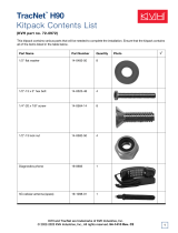
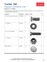
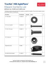
Kitpack Contents
The kitpack packaged with your antenna unit contains various
hardware and other materials that will be needed to complete the
TracVision system installation. Ensure that the kitpack contains
all of the items listed in Table 2-3.
Part Qty. KVH Part No.
3
⁄8"-16 x 3" hex head screws 4 14-0227-48
3
⁄8" flat washers 8 14-0229
3
⁄8"-16 hex nuts 4 14-0228
3
⁄8" lock washers 4 14-0230
3
⁄8" fiber shoulder washers 8 14-0336
Plastic screw covers 12 19-0088
Foam seal 1 24-0142
Tie-wraps 2 22-0013
Core clamp (ferrite) 1 29-0037-02
54-0166
10
TracVision 6 Technical Manual
Table 2-3
Kitpack Contents
Table 2-2
Recommended Switchplate-to-
Ship’s Power Cable Specifications

Choosing Component Locations
The major considerations in locating the TracVision components
are described below.
Cable Lengths
When determining component locations, keep in mind
accessibility and cable lengths between units. Lengths of these
cables are as follows:
Cable (Function) Length
Data Cable (Switchplate to Antenna Unit) 100 ft (30 m)
PC Cable (Switchplate to PC) 6 ft (2 m)
RF Cable (Antenna to IRD)* 100 ft (30 m)
Power Cable (Switchplate to Antenna Unit) 100 ft (30 m)
IRD Ground Cable (IRD to Switchplate) 50 ft (15 m)
* Not included with European quad-output LNB systems
Installation
54-0166
11
Table 2-4
Lengths of Provided
Belowdecks Cables

Choosing the Best Location for the TracVision Antenna
There are several factors to consider when choosing the location
for the TracVision antenna.
• Since the TracVision antenna requires a clear view
of the southern sky to receive satellite signals, the
ideal antenna site has an unobstructed view of the
horizon/satellite all around. The less blockage, the
better the system performs.
• Keep the antenna clear of any obstructions above
decks. The antenna requires a 10º to 80º look angle
to receive satellite signals.
• To minimize tracking errors, place the antenna
unit as close as possible to the intersection of the
vessel’s fore-and-aft centerline and midships.
• The mounting surface should be flat and strong
enough to carry the complete assembly (55 lbs/
25 kg). To prevent warpage to the antenna
baseplate, make sure that the mounting surface is
rigid so that it cannot flex when the vessel
vibrates. If necessary, add a strength member to
the mounting site to stiffen it.
• Be sure to account for the height and base
dimensions (see Figure 2-2 on the following page).
54-0166
12
TracVision 6 Technical Manual
Blocked!
TracVision Antenna
Vessel Platform
Mast
Figure 2-1
Antenna Blockage

Radar Concerns
The TracVision antenna must be kept out of line with nearby
radars, as their energy levels may overload the antenna’s front-
end circuits. In an ideal installation, the antenna is mounted four
feet (1.2 m) above and four feet (1.2 m) away from the radar
(measured from the center of the antenna dome to the center of
the radar).
The best placement for the TracVision antenna is above the radar.
However, if there will be a significant horizontal separation
between the radar and TV dome (i.e., at least 8 to 10 feet (2.5 to
3 m)), the TracVision antenna can be placed below the radar as
there will be little chance of signal blockage.
Installation
54-0166
13
Figure 2-2
Antenna Unit Dimensions
The radome exterior is treated
with a special finish selected for
compatibility with the dome material
and transparency to the satellite
signals. Application of additional
paints or finishes WILL degrade
performance, potentially beyond
acceptable limits.
A full-size template of the baseplate
mounting holes has been provided
at the back of this manual.
FWD
27.36"
(695 mm)
Compression Seal
4x .50"
(4x 13 mm)
26.2"
(665 mm)
12.0"
(305 mm)
6.0" (152 mm)
6.0" (152 mm)
12.0"
(305 mm)

Locating the Switchplate
A switchplate has been provided to serve as the hub of the
TracVision 6 wiring (with the exception of the RF cable, which
will be connected to the IRD). The switchplate includes an
On/Off switch and a DB9 maintenance port for easy access to the
antenna unit’s software and diagnostics. Follow the steps below
to select and prepare the switchplate mounting location.
1. Select a location to mount the TracVision 6
switchplate. It should be installed in a dry, flat
location within reach of the cables that will
connect to the antenna unit and allowing easy
access to the front panel.
2. Once you’ve decided on a suitable location, create
a panel cutout in the mounting surface.
Figure 2-3 illustrates the mounting dimensions
and a template has been provided in Appendix B.
The connecting cables will be routed through this
cutout.
54-0166
14
TracVision 6 Technical Manual
3.82"
(97 mm)
.32" (8 mm)
2.36"
(60 mm)
.16" (4 mm)
3.19"
(81 mm)
2.05"
(52 mm)
Panel Cutout
3
/32" (2.5 mm) dia
Figure 2-3
Switchplate Panel
Cutout Dimensions
A full-scale panel cutout template
has been provided in
Appendix B
on page 73.

2.2 Mounting the TracVision
Antenna
1. Make sure that you have chosen a suitable
mounting location based upon the guidelines in
“Choosing the Best Location for the TracVision
Antenna” on page 12.
2. Using the template provided at the back of this
manual or the dimensions shown in Figure 2-4, lay
out the four mounting bolt holes and cable access
hole at the mounting site. Make certain that the
“FWD” arrow is parallel with the vessel’s
centerline and pointed toward the bow.
3. Drill the four
1
⁄2" (13 mm) bolt holes and cut out the
3" (80 mm) diameter cable access hole (following
the layout in Step 2). Smooth the edges of the cable
access hole to protect the cables.
4. Bring the data cable, power cable, and RF cable(s)
from belowdecks up through the cable access hole
in the mounting surface (see Table 2-1 on page 9 to
determine the number of RF cables required).
Belowdecks, route the opposite end(s) of the RF
cable(s) to the IRD(s) or multiswitch; route the
opposite ends of the data cable and power cable
through the switchplate panel cutout.
Installation
54-0166
15
Figure 2-4
Antenna Mounting Holes Layout
Be careful not to strike the exposed
connectors extending from the
bottom of the baseplate or allow
them to carry the weight of the
antenna unit.
A full-size template of the baseplate
mounting holes has been provided
at the back of this manual.
F
W
D
DOME
26.2"
( 67 cm)
4 x 0.5"
(4 x 1.3 cm)
3"
( 7.6 cm)
12"
(30.5 cm)
6"
(15.2 cm)
12"
(30.5 cm)
6"
(15.2 cm)

5. Remove the antenna unit from its shipping carton
and set the radome aside in a safe place. If you
bring the radome topside, be sure to secure it with
a lanyard so that it does not fall overboard.
6. Remove the foam shipping restraints from the
antenna unit.
7. Place the foam seal in position on the mounting
surface with the hole centered over the cable
access cutout. Do not remove the paper backing at
this time. Scribe a line all around the seal.
8. Position the baseplate assembly in place over the
mounting holes and cable access, with the
baseplate’s “Forward” arrow (shown in Figure 2-5)
pointing toward the bow. Ensure that all holes line
up and that the connectors are centered over the
cable access as shown in Figure 2-6. Make any
necessary adjustments before seating the foam seal
in place permanently.
54-0166
16
TracVision 6 Technical Manual
Figure 2-5
Baseplate “Forward” Arrow
FWD
Figure 2-6
Baseplate/Foam Seal Orientation
(Bottom View)
The foam shipping restraints must
be removed before power is
applied. Save the restraints for
reuse and be sure to install them
whenever the antenna unit is
moved from place to place. See
Section 4.9, “Preparing for
Shipment” on page 67
for details.
For the antenna to work properly,
the baseplate’s “Forward” arrow
MUST be parallel with the vessel’s
centerline and pointed toward the
bow.
/