Sony TRINITRON KV-VF21M40 User manual
- Category
- Cassette players
- Type
- User manual
This manual is also suitable for

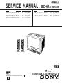
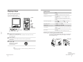
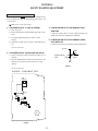
SERVICE MANUAL
CHASSIS
BC-4A
MODEL COMMANDER DEST. CHASSIS NO.
MODEL COMMANDER DEST. CHASSIS NO.
KV-VF21M40
RM-956 E SCC-P10A-A
KV-VF21M70
RM-956 ME SCC-P11A-A
KV-VF21M70
RM-956 JE SCC-P12A-A
KV-VF21M70
RM-956 HK SCC-P09B-A
KV-VF21M77
RM-955 HK SCC-P09A-A
21
∗ Please file according to model size. ....
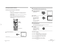
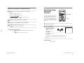
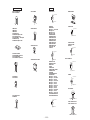
TRINITRON
®
COLOR VIDEO TV
COUNTER RESET
t
MENU
REW
A/B
EJECT
TIMER REC
G-CODE
ON/OFF
TAPE SPEED
INDEX
zREC
GAME
2
PROGR
1
6
7
0C
9
4
32
5
8
X PAUSE
x STOP
m
FF
M
Z
.>
PLAY
ENTER
PIC MODE
-/--
H
COUNTER RESET
t
MENU
REW
EJECT
TIMER REC
G-CODE
ON/OFF
TAPE SPEED
INDEX
zREC
GAME
2
PROGR
1
6
7
0C
9
4
32
5
8
X PAUSE
x STOP
m
FF
M
Z
.>
PLAY
ENTER
PIC MODE
-/--
H
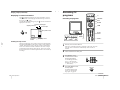
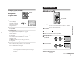
RM-955
RM-956
PAL NTSC
(VF21M77 ONLY)
®

– 2 –
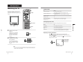
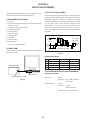
SPECIFICATIONS
TV Section
Television system B/G, I, D/K, M
Color system PAL/SECAM and
NTSC
3.58
/NTSC
4.43
Bilingual system NICAM bilingual I
(VF21M77 ONLY)
Channel coverage See “Receivable
channels and channel
display”
Picture tube Trinitron
21 inches (approx. 50.7
cm measured
diagonally)
Antenna in 75-ohm antenna socket
for VHF/UHF
Video Section
Format VHS standard
Video recording system
Rotary 2-head helical
scanning system
Audio recording system
Monaural
Video signal PAL/MESECAM/
NTSC
Tape speed PAL/MESECAM
SP: 23.39 mm/sec.
LP: 11.70 mm/sec.
NTSC
SP: 33.35 mm/sec.
EP: 11.11 mm/sec.
Maximum recording time
PAL/MESECAM
SP: 240 minutes with
E-240
LP: 480 minutes with
E-240
NTSC
SP: 180 minutes with
T-180
EP: 540 minutes with
T-180
Inputs and Outputs
Inputs t1, t2/GAME IN
(video): phono jack
1 Vp-p, 75 ohms,
unbalanced,
sync negative
9 (audio): phono jack
Input level:
500 mVrms
Headphones jack Minijack
General
Clock Quartz locked
Power requirements 110-240 V AC, 50/60Hz
Power consumption 123 W
Operating temperature
5˚ C to 40˚ C
(41˚ F to 104˚ F)
Storage temperature –20˚ C to 60˚ C
(–4˚ F to 140˚ F)
Dimensions 489 x 500 x 485 mm
(19
3
/
8
x 19
3
/
4
x 19
1
/
8
inches)
Mass 27.5 kg (60 lb 10 oz.)
Supplied accessories
Remote control
Two R6 (size AA)
batteries
Stabilizer band
Two clamps
Two wood screws
AC plug adaptor
(E/ME/JE model)
These operating
instructions
Design and specifications are subject to
change without notice.

– 3 –
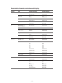
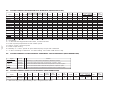
Receivable channels and channel display
System Area Channel coverage Channel display
B/G, H Middle East/Asia E-2 to E-12 C02 to C12
E-21 to E-69 C21 to C69
Indonesia 1A C01
2 to 11 C03 to C12
Morocco M-4 to M-7 C70 to C73
M-8 to M-10 C08 to C10
CATV S-01 to S-05 S42 to S46
S-1 to S-41 S01 to S41
I Hong Kong/ B-21 to B-69 C21 to C69
United Kingdom
Ireland A, B, C,....J C01 to C10
South Africa 4 to 13 C04 to C13
21 to 68 C21 to C68
Angola 1 C00
2 to 3 C02 to C03
CATV S-01 to S-05 S42 to S46
S-1 to S41 S01 to S41
D/K, K1 East European R-1 to R-12 C01 to C12
coutries R-21 to R-60 C21 to C60
China C-1 C01
C-2 C02
C-3 C13
C-4 C03
C-5 C04
C-6 C14
C-7 to C-12 C06 to C11
C-13 to C-24 C21 to C32
C-25 to C-47 C38 to C60
C-48 to C-57 C61 to C70
Ivory Coast 1 to 3 C71 to C73
CATV S-1 to S-39 S01 to S39
M America A-2 to A-13 C02 to C13
A-14 to A-69 C14 to C69
CATV A-8 S01
A-7 S05
A-6 S06
A-5 to A-1 S95 to S99
A to E S14 to S18
F to W+28 S19 to S64
W+29 to W+58 S65 to S94

– 4 –
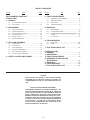
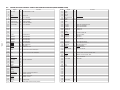
TABLE OF CONTENTS
Section Title Page Section Title Page
SELF DIAGNOSIS FUNCTION...................................... 5
[ TV SECTION]
1. GENERAL
1-1. KV-VF21M40/VF21M70 ........................................ 8
1-2. KV-VF21M77 ......................................................... 35
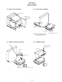
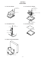
2. DISASSEMBLY
2-1. Rear Cover Removal ............................................... 65
2-2. Chassis Assy Removal ............................................ 65
2-3. Service Position (A Board) ..................................... 65
2-4. A Board Removal .................................................... 65
2-5. Harnes Location ...................................................... 66
2-6. Picture Tube Removal ............................................. 67
3. SET-UP ADJUSTMENTS
3-1. Beam Landing ......................................................... 68
3-2. Convergence ............................................................ 69
3-3. Focus Adjustment .................................................... 70
3-4. Screen (G2) Adjustment .......................................... 70
3-5. White Barance Adjustment ..................................... 71
3-6. Picture Distortion Adjustment ................................. 71
4. SAFETY RELATED ADJUSTMENT...................... 72
CAUTION
SHORT CIRCUIT THE ANODE OF THE PICTURE TUBE AND
THE ANODE CAP TO THE METAL CHASSIS, CRT SHIELD, OR
CARBON PAINTED ON THE CRT, AFTER REMOVING THE AN-
ODE.
SAFETY-RELATED COMPONENT WARNING!!
COMPONENTS IDENTIFIED BY SHADING AND MARK ! ON
THE SCHEMATIC DIAGRAMS, EXPLODED VIEWS AND IN THE
PARTS LIST ARE CRITICAL FOR SAFE OPERATION. REPLACE
THESE COMPONENTS WITH SONY PARTS WHOSE PART
NUMBERS APPEAR AS SHOWN IN THIS MANUAL OR IN SUP-
PLEMENTS PUBLISHED BY SONY. CIRCUIT ADJUSTMENTS
THAT ARE CRITICAL FOR SAFE OPERATION ARE IDENTIFIED
IN THIS MANUAL. FOLLOW THESE PROCEDURES WHEN-
EVER CRITICAL COMPONENTS ARE REPLACED OR IM-
PROPER OPERATION IS SUSPECTED.
5. CIRCUIT ADJUSTMENTS
5-1. Adjustments with Commander................................ 73
5-2. Adjustment Method................................................. 74
5-3. Service Data ............................................................ 75
5-4. A Board Adjustment................................................ 77
6. DIAGRAMS
6-1. Block Diagrams....................................................... 79
6-2. Circuit Boards Location .......................................... 83
6-3. Printed Wiring Boards and Schematic Diagrams .... 83
• A Board .................................................................... 84
• CV, F Boards ............................................................ 91
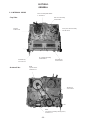
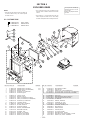
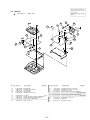
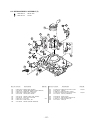
6. EXPLODED VIEWS
6-1. Picture Tube ............................................................ 124
6-2. Chassis..................................................................... 125
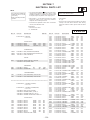
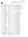
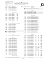
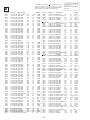
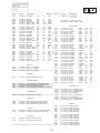
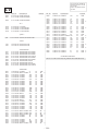
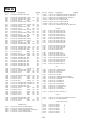
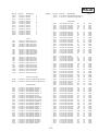
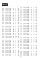
7. ELECTRICAL PARTS LIST ...................................... 129
[ VIDEO SECTION]
1. GENERAL ....................................................................... 96
2. DISASSEMBLY ............................................................. 97
3. CIRCUIT ADJUSTMENTS ........................................ 98
4. INTERFACE, IC PIN FUNCTION
DESCRIPTION .............................................................. 101
5. DIAGRAMS..................................................................... 105
6. EXPLODED VIEWS ..................................................... 126
7. ELECTRICAL PARTS LIST ...................................... 135

– 5 –
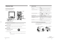
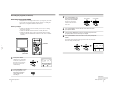
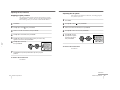
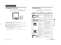
1. OUTLINE
• The units in this manual contain a self-diagnostic function.
• If an error occurs, the STANDBY lamp will automatically begin to flash.
The number of times the lamp flashes translates to a probable source of the problem. A definition of the STANDBY lamp
flash indicators is listed in the instruction manual for the user’s knowledge and reference.
• If an error symptom cannot be reproduced, the remote commander can be used to review the failure occurrence data
stored in memory to reveal past problems and how often these problems occur.
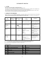
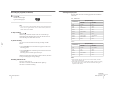
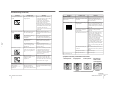
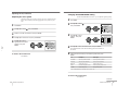
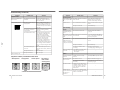
2. DIAGNOSTIC TEST INDICATORS
• When an errors occurs, the STANDBY lamp will flash a set number of times to indicate the possible cause of the problem.
If there is more than one error, the lamp will identify the first of the problem areas.
• Result for all of the following diagnostic items are displayed on screen. No error has occured if the screen displays a “0”.
Diagnostic
Item
Description
• Power does not
turn on
No. of times
STANDBY lamp
flashes
Does not light
Self-diagnostic
display/Diagnostic
result
—
Probable
Cause
Location
• Power cord is not plugged
in.
• Fuse is burned out F901
Detected
Symptoms
• Power does not come on.
• No power is supplied to the
TV.
• AC power supply is faulty.
Note 1: If a + B overcurrent is detected, stoppage of the vertical deflection is detected simultaneously.
The symptom that is diagnosed first by the microcontroller is displayed on the screen.
Note 2: Refer to screen (G2) Adjustment in section 3-4 of this manual.
SELF DIAGNOSTIC FUNCTION
• FBT
• Q802 (H OUT) shorted
2 : 0 or
2 : 1
4 : 1
2 times
4 times
5 times
• Vertical deflection
stopped
• White balance
failure (no
PICTURE)
• +B overcurrent
(OCP) or
overvoltage
(OVP)
• Has entered standby state
after horizontal raster.
• Vertical deflection pulse is
stopped.
• Horizontal deflection
stopped.
• Power line is shorted or
power supply is stopped.
4 : 0
or
4 : 1
• IC501
• IC301 !¢ pin
• IC606
• Q802 (H OUT) shorted
• Q803
• Q608
• R803 open
5 : 0
or
5 : 1
• On standby state.
• Load on power line is
shorted
(at the same time 4 : 1 on
display).
at the same
time
(Note 1)
•CRT
• IC301
• IC701 - IC703, Q701
(CV board)
• G2 is improperly adjusted.
(Note 2)
• No raster is generated.
• CRT cathode current
detection reference pulse
output is small.
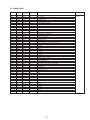
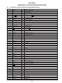
Code Coutents
00h NO EMG
10h CAM encode NG during unloading
11h CAM encode NG during unloading
12h CAM encode NG at intial
20h T reel NG during unloading
21h S reel FG NG
22h T reel FG NG
23h S reel FG NG
24h T reel FG NG at initial
25h S reel FG NG at initial
Code Coutents
30h Capstan FG NG at initial
31h Capstan FG NG
40h Drum FG NG
41h Drum FG NG at initial
42h Drum FG NG
43h Drum PG NG
44h Drum PG NG
50h DEW
60h FL NG
70h DEW eject NG
• VCR EMG code List

– 6 –
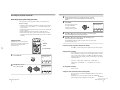
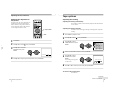
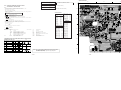
4. SELF-DIAGNOSTIC SCREEN DISPLAY
• For errors with symptoms such as “power sometimes shuts off” or “screen sometimes goes out” that cannot be confirmed,
it is possible to bring up past occurances of failure for confirmation on the screen:
[To Bring Up Screen Test]
• In standby mode, press buttons on the remote commander sequentially in rapid succession as shown below:
[Screendisplay] / channel [5] / Sound volume [-] / Power ON u
˘
Note that this differs from entering the service mode (mode volume [+]).
Self-Diagnosis screen display
5. HANDLING OF SELF-DIAGNOSTIC SCREEN DISPLAY
• Since the diagnostic results displayed on the screen are not automatically cleared, always check the self-diagnostic
screen during repairs. When you have completed the repairs, clear the result display to “0”.
• Unless the result display is cleared to “0”, the self-diagnostic function will not be able to detect subsequent faults after
completion of the repairs.
[Clearing the result display]
• To clear the result display to “0”, press buttons on the remote commander sequentially as shown below when the diagnos-
tic screen is being displayed.
• Pay attention when perform by the service mode, other all electric adjustment data will be rewrite.
Channel [8] / [0]
[Quitting Self-diagnostic screen]
• To quit the entire self-diagnostic screen, turn off the power switch on the remote commander or the main unit.
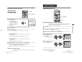
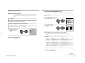
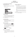
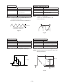
3. DISPLAY OF STANDBY LIGHT FLASH COUNT
* One flash count is not used for self-diagnostic.
< Diagnostic Item >
• +B OCP/OVP
• White balance failure
STOPPING THE STANDBY FLASH
• Turn off the power switch on the TV main unit or unplug the power cord from the outlet to stop the STANDBY lamp from flashing.
• Vertical deflection stopped
2 times
4 times
5 times
Lamp ON 0.3 sec.
Lamp OFF 0.3 sec.
Lamp OFF 3.0 sec.
< Flash Count >
STANDBY lamp (RED)
Numeral "0" means that no fault has been detected.
Numeral "1" means a fault has been detected.
diagnostic item : result
SELF CHECK
VCR :
--
--
1: 2 : 1 3 : 4 : 0 5 : 1
Note: Though "1: , 3:" indicated, not using.
EMG code.
+

– 7 –
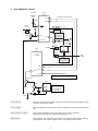
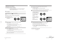
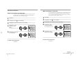
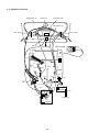
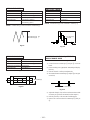
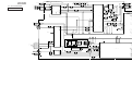
6. SELF-DIAGNOSTIC CIRCUIT
[+Bovercurrent] Owing to current increase voltage of R615 decrease and that it make PM601 pin 8 to
become LOW and OFF RY601.
[+Bovervoltage] When +B voltage become more than 142.5V, PM601 8 pin become LOW and RY601
OFF.
[Verticaldeflectionstopped] Detect Vertical deflection Pulse lost by IC001 ^º pin of micro computer.
Mute the picture at !∞ pin of IC301 that performed by Y/C/J.
[Whitebalance] Detect when R.G.B. output wrong level balance of automatic white balance detecting
standard pulse which detect cathode current, or which become low almost.
CRT
7
3
62
52
60
49
47
41
A
42
43
A
37
21
34
35
15
SCL1
SDA1
V PULSE
LED1
OVP
VCR
RY601
RELAY
Q601
ITEM 2.
Over voltage
Detection(OCP)
BOOST
VCC
IC501
IC301
Y/C/J
HP/
PROTECT
SDA
SCL
IK IN
VM OUT
R,G,B STOP
To item 2 and 5 via bus line
MEMORY
V
•
STOP
IC004
R
•
G
•
B
ITEM 5.
Auto cut-off white balance detection(AKB)
8
3
1
PM601
D1308
PM21
FBT
(T801)
C504
✩
Diagnostic screen display
Q606
R614
D502
R656
+B LINE
R615
Q502
Q501
C505
R510
IC001
µ-COM
LED flash
STANDBY
lamp
34
21
ITEM 3
Over current
Detection(OVP)
ITEM 4.
Vertical Deflection
output Detection
(V
•
STOP)
R613
R611

– 8 –
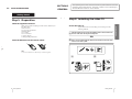
SECTION 1
GENERAL
The operating instructions mentioned here are partial abstracts from the
Operating Instruction Manual. The page numbers of the Operating In-
struction Manual remein as in the manual.
1-1. KV-VF21M40/VF21M70
4
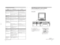
Getting Started
Getting Started
Step 1: Preparation
Check the supplied accessories
When you have taken everything out of the carton, check that you
have these items:
• Remote control
• Two R6 (size AA) batteries
• Stabilizer band
• Two clamps
• Two wood screws
• AC plug adaptor
• These operating instructions
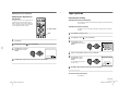
Insert the batteries into the remote control
Note
• Do not use old batteries or different types of batteries together.
5
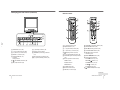
Getting Started
Getting Started
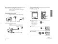
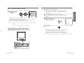
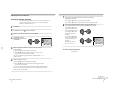
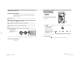
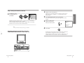
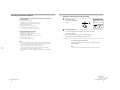
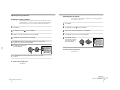
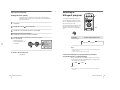
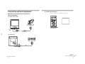
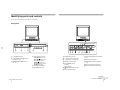
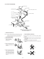
Step 2: Installing the video TV
Secure the video TV
To prevent the video TV from falling, secure it using one of the
following methods:
A
With the supplied screws, attach the stabilizer band to the TV stand and to
the rear of the video TV using the existing hole.
OR
B
Pass a cord or chain through the clamps and secure them to the rear of the
video TV and a wall or pillar.
A
B
20
mm
3.8 mm

– 9 –
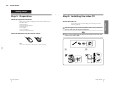
6
Getting Started
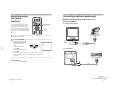
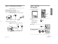
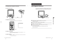
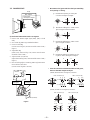
Step 3: Connecting the antenna
For better TV reception and clear recordings, connect an outdoor
antenna to your video TV.
Connecting an outdoor antenna
To connect a VHF antenna or a combination VHF/UHF
antenna—75-ohm coaxial cable (round)
Attach an IEC antenna connector to the 75-ohm coaxial cable.
Plug the connector into the 8 (antenna) socket of the video TV.
To connect both VHF and UHF antennas
Attach the antenna cable ends to the VHF/UHF mixer (not
supplied).
Plug the mixer into the 8 (antenna) socket of the video TV.
On a wall
75-ohm coaxial cable
Rear
VHF/UHF
antenna
or
Rear
300-ohm twin-lead cable
VHF/UHF mixer
(not supplied)
UHF antenna
VHF antenna
7
Getting Started
Getting Started
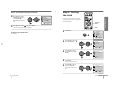
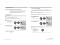
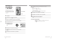
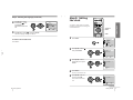
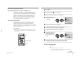
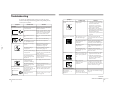
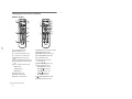
Step 4: Selecting
the language
You can change the menu and on-screen
information language to Chinese.
1
Press ?/1 to turn on the
video TV.
When the TV is in standby
mode (the 1 indicator on
the video TV is lit in red),
press ?/1 , PROGR +/– or
a number button on the
remote control.
2
Press MENU.
3
Press M or m to select
,
then press ENTER.
continued
A/B
G-CODE
COUNTER RESET
t
MENU
REW
EJECT
TIMER REC
ON/OFF
TAPE SPEED
INDEX
zREC
GAME
132
X PAUSE
x STOP
m
FF
M
Z
.>
PLAY
ENTER
PIC MODE
H
?/1
?/1
M/,/m/</
ENTER
MENU
MENU
SELECT
SET UP
TV SET UP
VIDEO SET UP
LANGUAGE/ :ENGLISH
PIC ROTATION
3
ENTER
PLAY
ENTER
H
PLAY
ENTER
H
SELECT
PICTURE MODE
·
DYNAMIC
·
STANDARD
·
SOFT
·
PERSONAL
ADJUST
3
ENTER

– 10 –
8
Getting Started
Step 4: Selecting the language (continued)
4
Press M or m to select
LANGUAGE/
, then
press ENTER.
The selected item turns
red.
5
Press M or m to select
, then press ENTER.
The menu language changes to Chinese.
To return to the normal screen
Press MENU.
PLAY
ENTER
H
PLAY
ENTER
H
SELECT
SET UP
TV SET UP
VIDEO SET UP
LANGUAGE/ :ENGLISH
PIC ROTATION
3
ENTER
9
Getting Started
Getting Started
Step 5: Setting
the clock
You need to set the clock to use timer
recording, Quick-Timer recording and
on-timer functions.
1
Press MENU.
2
Press M or m to select
,
then press ENTER.
3
Press M or m to select
CLOCK SET , then press
ENTER.
4
Press ENTER.
The day section turns red.
5
Press M or m to set the
day, then press ,.
The month section turns
red.
continued
A/B
G-CODE
COUNTER RESET
t
MENU
REW
EJECT
TIMER REC
ON/OFF
TAPE SPEED
INDEX
zREC
GAME
132
X PAUSE
x STOP
m
FF
M
Z
.>
PLAY
ENTER
PIC MODE
H
M/,/m/</
ENTER
MENU
SELECT
PICTURE MODE
·
DYNAMIC
·
STANDARD
·
SOFT
·
PERSONAL
ADJUST
3
ENTER
SELECT
TIMER
ON TIMER SET
CLOCK SET
3
ENTER
CLOCK SET
31.12.1999 FRI 10:00
3
ENTER
MENU
PLAY
ENTER
H
PLAY
ENTER
H
PLAY
ENTER
H
PLAY
ENTER
H
PLAY
ENTER
H
PLAY
ENTER
H
SELECT
CLOCK SET
27.12.1999 MON 10:00
3
ENTER

– 11 –
10
Getting Started
Step 5: Setting the clock (continued)
6
Press M, m or , to set the month, year, hour and minutes in
the same way as in step 5, then press ENTER.
The clock starts working.
To return to the normal screen
Press MENU.
If you have made a mistake while setting the clock
Press < to go back to the item to be changed and set the correct
digits using M or m, then press ,.
Note
• If power is interrupted or you disconnect the AC power cord, you have to
re-set the clock.
11
Getting Started
Getting Started
Step 6: Setting the channels
Presetting channels
automatically
You can preset up to 100 channels.
Automatic presetting is the easiest way
to setup your video TV if you want to
preset all receivable channels at once.
To preset the channels manually, see
page 30.
1
Press MENU.
2
Press M or m to select
,
then press ENTER.
3
Make sure TV SET UP is
selected, then press
ENTER.
4
Press M or m to select TV
SYS, then press ENTER.
The selected item turns red.
Press M or m to select the
TV system (B/G, I, D/K or
M) and press ENTER.
continued
A/B
G-CODE
COUNTER RESET
t
MENU
REW
EJECT
TIMER REC
ON/OFF
TAPE SPEED
INDEX
zREC
GAME
X PAUSE
x STOP
m
FF
M
Z
.>
PLAY
ENTER
PIC MODE
H
M/,/m/</
ENTER
MENU
SELECT
PICTURE MODE
·
DYNAMIC
·
STANDARD
·
SOFT
·
PERSONAL
ADJUST
3
ENTER
SELECT
SET UP
TV SET UP
VIDEO SET UP
LANGUAGE/ :ENGLISH
PIC ROTATION
3
ENTER
SELECT
TV SET UP
AUTO PROGRAM
MANUAL PROGRAM
SKIP : PR 01 OFF
TV SYS : B/G
COL SYS : AUTO
INTELLIGENT VOL : OFF
3
ENTER
MENU
PLAY
ENTER
H
PLAY
ENTER
H
PLAY
ENTER
H
PLAY
ENTER
H
PLAY
ENTER
H
SELECT
TV SET UP
AUTO PROGRAM
MANUAL PROGRAM
SKIP : PR 01 OFF
TV SYS : B/G
COL SYS : AUTO
INTELLIGENT VOL : OFF
3
ENTER

– 12 –
12
Getting Started
Step 6: Setting the channels (continued)
5
Press M or m to select
AUTO PROGRAM, then
press ENTER.
Presetting starts from program position 1. The preset program and channel
numbers are displayed on the screen in sequence.
When presetting is finished, program position 1 appears again. All available
channels are now stored on successive number buttons.
Tip
• To stop automatic channel presetting, press MENU.
Presetting channels automatically using the
TUNER PRESET ON/OFF button on the video TV
PUSH
t
GAME
2
PROGR
–PLAY–REW FF PAUSE REC
QUICK TIMER
TIMER REC
REC
STOP
q
Xx
mM
H
TUNER PRESET
ON/OFF
GAME
t
?/1
AUTO PROGRAM
PR : 01
TV SYS : B/G
CH : 01
3
ENTER
PLAY
ENTER
H
PLAY
ENTER
H
13
Getting Started
Getting Started
1
Press ?/1 to turn on the video TV.
When the TV is in standby mode (the 1 indicator on the video TV
is lit in red), press ?/1 , PROGR +/– or a number button on the
remote control.
2
Press TUNER PRESET ON/OFF with a pointed object.
Do not use an item (such as a pencil) that might break off when
inserted.
3
Press t to select the TV
system of the channels
which you want to preset.
4
Press GAME.
Presetting starts from program position 1. The preset program and
channel numbers are displayed on the screen in sequence.
When presetting is finished, program position 1 appears again. All
available channels are now stored on successive number buttons.
TUNER PRESET
PR : 01
TV SYS : B/G
CH : 01
Press t
for system selection.
GAME to start.
t
GAME

– 13 –
14
Basic Operations
Basic Operations
Watching the TV
This section explains various functions
used while watching the TV. Most
operations can be done using the remote
control.
1
Press ?/1 to turn on the
video TV.
When the TV is in standby
mode (the 1 indicator on
the video TV is lit in red),
press ?/1 on the remote
control.
2
Press PROGR +/– or the
number buttons to select
the TV channel.
For double digit numbers,
press -, then the numbers
(e.g., for 25, press -, then
2 and 5).
Note
• You can also select the channel number directly with the number buttons.
Press C (once for regular channels, twice for cable channels), the desired
number buttons, then ENTER.
A/B
G-CODE
COUNTER RESET
t
MENU
REW
EJECT
TIMER REC
ON/OFF
TAPE SPEED
INDEX
zREC
GAME
2
PROGR
1
6
7
0C
9
4
32
5
8
X PAUSE
x STOP
m
FF
M
Z
.>
PLAY
ENTER
PIC MODE
-/--
H
PROGR+/–
?/1
?/1
PROGR+/–
Number buttons
PROGR
1
6
7
0C
9
4
32
5
8
-/--
2+/–
t
%
PIC MODE
2+/–
15
Basic Operations
Additional tasks
To Press
Turn off temporarily ?/1 on the remote control.
The 1 indicator on the video TV lights up in red.
Turn off the main power ?/1 on the video TV.
The w indicator on the video TV lights up in orange.
Adjust the volume 2 +/–.
Mute the sound %.
Watch the video input t to select “t1” or “t2”(see page 48).
(from a connected VCR, To return to the TV screen, press t again.
camcorder, etc.)
Selecting the picture mode
Press PIC MODE repeatedly until the desired picture mode is selected.
Select To
DYNAMIC receive high contrast pictures.
STANDARD receive normal contrast pictures.
SOFT receive low contrast pictures.
PERSONAL receive the latest picture settings from the ADJUST
option in the PICTURE MODE menu (see page 35).
Displaying on-screen information
Press to display the following on-screen information.
To have the program number and channel number stay on the
screen, press
again.
To make the information disappear, press
until no information is
displayed on the screen.
Basic Operations
27.11 SAT
20:00
12
C30
MAIN
Program position
Channel number
Current date and time

– 14 –
16
Basic Operations
Playing a tape
This section shows you how to play a
tape. Other convenient functions you
can use while playing a tape are
explained in “Additional Operations.”
1
Press ?/1 to turn on the video TV.
When the TV is in standby mode (the 1 indicator on the video TV is lit in
red), skip this step.
2
Insert a cassette.
If you insert a cassette with its safety tab removed, playback starts
automatically.
3
Press PLAY N.
Playback starts. On-screen
information is displayed
for a few seconds.
Note
• The picture’s color may be affected when playing a MESECAM-recorded
tape in the LP mode.
–
PLAY–REW FF PAUSESTOP
Xx
mM
H
A/B
G-CODE
COUNTER RESET
t
MENU
REW
EJECT
TIMER REC
ON/OFF
TAPE SPEED
INDEX
zREC
GAME
132
X PAUSE
x STOP
m
FF
M
Z
.>
PLAY
ENTER
PIC MODE
H
?/1
?/1
EJECTZ
PAUSEX
FFM
PLAYN
STOPx
REWm
COUNTER RESET
EJECTZ
PAUSEX
FFM
PLAYN
REWm
STOPx
PLAY
ENTER
H
17
Basic Operations
Additional tasks
To Press
stop playback STOP x.
The video TV goes back to the normal TV picture.
stop playback for a moment PAUSE X.
Press PAUSE X again or press PLAY N to resume
playback.
If you leave your video TV in pause mode, normal
playback resumes after about 5 minutes to prevent tape
damage.
search a tape at high speed REW m
(rewind) or FF M
(fast-forward)
during playback.
To resume normal playback, press PLAY N.
fast-forward the tape STOP x, then press FF M.
rewind the tape STOP x, then press REW m.
view the picture in fast-forward
and hold FF M during fast-forward or REW m during
or rewind mode rewind.
When you release the button, fast-forward or rewind
mode is resumed.
eject a cassette EJECT Z.
You can eject the cassette even if the power is off.
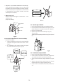
Protecting your cassette against accidental erasure
To prevent accidental erasure, break off the safety tab as illustrated.
To record on a cassette without a safety tab, simply cover the tab
hole with adhesive tape.
Safety tab
Adhesive tape
continued

– 15 –
18
Basic Operations
Playing a tape (continued)
Displaying on-screen information
Press to display the following on-screen information. To show
only the amount of remaining tape and the linear tape counter on
the screen, press
again.
To make the information disappear, press
until no information is
displayed on the screen.
Resetting the tape counter
The tape counter helps you to locate a certain scene after playback.
Press COUNTER RESET on the remote control to set the counter to
“0:00:00” before playing a tape. The tape counter is automatically
reset to zero whenever a cassette is inserted. The video TV keeps
counting the length of the tape being played. Note, however, that
the tape counter does not count the portions that do not contain any
recordings.
27.11 SAT
20:00
S
SP
2
:
05
:
10
E
M
SE
Amount of remaining tape
Beginning of the tape
End of the tape
Tape operation mode
Linear tape counter
Tape speed
Current date
and time
19
Basic Operations
Recording TV
programs
Recording TV programs
1
Press ?/1 to turn on the video TV.
If the TV is in standby mode (the 1 indicator on the video TV is lit in
red), the video TV will turn on automatically when a cassette is
inserted.
2
Insert a cassette with a safety tab.
3
Press PROGR+/– or the
number buttons to select
the program position.
For double digit numbers,
press -, then press the
numbers (e.g., for 25, press
-, then 2 and 5).
4
Press TAPE SPEED to select
the tape speed.
For details about the tape
speed, see “Selecting the
tape speed” on page 21.
–PLAY –REW FF PAUSE RECSTOP
Xx
mM
H
A/B
G-CODE
COUNTER RESET
t
MENU
REW
EJECT
TIMER REC
ON/OFF
TAPE SPEED
INDEX
zREC
GAME
2
PROGR
1
6
7
0C
9
4
32
5
8
X PAUSE
x STOP
m
FF
M
Z
.>
PLAY
ENTER
PIC MODE
-/--
H
?/1
?/1
TAPE SPEED
PROGR+/–
PAUSEX
RECz
STOPx
RECz
PAUSEX
STOPx
Number
buttons
PROGR+/–
PROGR
1
6
7
0C
9
4
32
5
8
-/--
TAPE SPEED
continued

– 16 –
20
Basic Operations
Recording TV programs (continued)
5
Press REC z.
The REC indicator lights
up and recording begins.
Note
• You can also select the channel number directly with the number buttons.
Press C (once for regular channels, twice for cable channels), the desired
number buttons, then ENTER.
To stop recording
Press STOP x.
When the tape reaches the end, the video TV rewinds the tape
automatically to the beginning, then stops. This function does not
work when the power of the video TV is off.
To pause recording
You can cut out an unwanted scene during recording with this
button.
1 Press PAUSE X when an unwanted scene appears on the screen.
Recording pauses.
2 Press PAUSE X again to release the pause mode at the end of the
unwanted scene.
Recording resumes from the point set in step 1.
When the recording pause mode lasts for about 5 minutes, the video
TV stops recording to prevent tape damage.
Recording with the TV off
Press ?/1 on the video TV.
The video TV is turned off and the w indicator lights up.
The video TV continues recording.
zREC
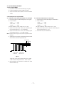
21
Basic Operations
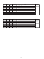
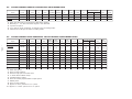
Selecting the tape speed
The chart below shows the recording/playback time available in
each mode.
PAL, MESECAM
Cassette tape
Tape speed setting
SP mode LP mode
E-30 30 min. 1 hr.
E-60 1 hr. 2 hrs.
E-90 1 hr 30 min. 3 hrs.
E-120 2 hrs. 4 hrs.
E-150 2 hrs 30 min. 5 hrs.
E-180 3 hrs. 6 hrs.
E-195 3 hrs 15 min. 6 hrs 30 min.
E-210 3 hrs 30 min. 7 hrs.
E-240 4 hrs. 8 hrs.
NTSC
Cassette tape
Tape speed setting
SP mode EP mode
T-30 30 min. 1 hr 30 min.
T-60 1 hr. 3 hrs.
T-120 2 hrs. 6 hrs.
T-160 2 hrs 40 min. 8 hrs.
T-180 3 hrs. 9 hrs.
Notes
• In the SP mode, the tape runs twice as fast as the LP mode, and three
times as fast as the EP mode.
• When a PAL format cassette is used with the NTSC system for recording,
the actual recording time is shorter than the standard recording time
stipulated on the cassette.
continued

– 17 –
22
Basic Operations
Recording TV programs (continued)
Recording using QUICK-TIMER
The Quick-Timer recording function allows you to preset your video
TV to record one program within a 24-hour period. For setting the
Quick-Timer, use QUICK TIMER on the video TV.
Before you begin
• Make sure that the clock is set correctly. If it is not, see “Setting
the clock” on page 9.
• Make sure that the loaded cassette has its safety tab intact.
• Make sure that the video TV does not enter the timer recording
standby mode (the TIMER REC indicator on the video TV should
not be lit.)
1
Press QUICK TIMER.
When the TV is in standby
mode (the 1 indicator on
the video TV is lit in red),
the power is turned on
automatically.
2
Press TAPE SPEED to select
the tape speed, SP or LP.
EP cannot be selected
when making timer
recordings.
A/B
G-CODE
COUNTER RESET
t
MENU
REW
EJECT
TIMER REC
ON/OFF
TAPE SPEED
INDEX
zREC
GAME
X PAUSE
x STOP
m
FF
M
Z
.>
PLAY
ENTER
PIC MODE
H
QUICK TIMER
TAPE SPEED
QUICK TIMER
PUSH
SELECT
START
OK CHANGE CLEAR
TAPE SPEED : SP
27
SAT
20:00 0
H
15
M
12
PROG
QUICK TIMER 27 SAT 20:00
ENTER
TAPE SPEED
23
Basic Operations
3
Turn QUICK TIMER to set
the hour of the start time,
then press QUICK TIMER.
The hour is set and the
minute of the start time
turns red.
4
Turn QUICK TIMER to set the minute of the start time, then
press QUICK TIMER.
5
Use the QUICK TIMER dial to set the recording time period and
program position in the same way as in step 3.
6
Turn QUICK TIMER to move the cursor to OK, then press QUICK
TIMER.
The Quick Timer indicator lights up and the video TV enters the
timer recording standby mode.
QUICK TIMER
PUSH
QUICK TIMER
PUSH
QUICK TIMER
PUSH
QUICK TIMER
PUSH
SELECT
START
OK CHANGE CLEAR
TAPE SPEED : SP
27
SAT
23:15 1
H
15
M
12
PROG
QUICK TIMER 27 SAT 20:00
ENTER
continued

– 18 –
24
Basic Operations
Recording TV programs (continued)
The QUICK TIMER button changes the following when turned clockwise
or counterclockwise
• When setting the start time:
The hour increases or decreases by one hour.
The minutes increase or decrease by one minute.
• The recording time period:
Increases or decreases by 15 minutes.
• The program position changes as follows:
1... y 8... y 12... y t1 y t2 y 0 y 1
If the QUICK TIMER button is pressed
• When the Quick Timer is not set:
The display for setting the Quick Timer appears.
• When the Quick Timer is set:
The display for checking the Quick Timer appears.
• When the clock is not set:
The CLOCK SET display appears.
Note
• When you turn QUICK TIMER to move the cursor to OK and then press
it, one of the following messages may appear depending on the cassette
used. If a message appears, the recording is canceled.
- Put in a tape. The program recording is canceled.
- Put in a tape with safety tab. The program recording is canceled.
- Tape ran out. The program recording is canceled.
Insert a cassette for recording, rewind the tape and press QUICK TIMER
again.
25
Basic Operations
Changing or canceling the Quick Timer settings
1
Press QUICK TIMER.
The QUICK TIMER display
appears.
2
Change the settings:
(1) Turn QUICK TIMER to move the cursor to CHANGE, then
press QUICK TIMER.
(2) Change the settings according to steps 2 through 7 of
“Recording using QUICK-TIMER” on pages 22 and 23.
To cancel the Quick Timer settings
Turn QUICK TIMER to move the cursor to CLEAR, then press
QUICK TIMER.
Note
• You cannot cancel the Quick Timer settings with the remote control.
SELECT
START
Programmed as below
OK
CHANGE CLEAR
TAPE SPEED : SP
27
SAT
23:15 1
H
15
M
12
PROG
QUICK TIMER 27 SAT 20:00
ENTER
QUICK TIMER
PUSH
continued

– 19 –
26
Basic Operations
Recording TV programs (continued)
Recording TV programs using the timer
You can preset up to five programs within a one-month period.
Before you begin
• When the TV is in standby mode (the 1 indicator on the video TV
is lit in red), press ?/1 , PROGR +/– or a number button on the
remote control.
• Make sure that the clock is set correctly. If it is not, see “Setting the
clock” on page 9.
• Make sure that the loaded cassette has its safety tab intact.
• Make sure that the video TV does not enter the timer recording
standby mode (the Quick Timer indicator on the video TV should
not be lit.)
Setting the timer
Example: How to record a program
broadcast on program position 6 from
21:00 to 22:00 on Sunday, 28th
November 1999.
1
Press TIMER REC.
2
Press M or m to set the
date , then press ,.
A/B
G-CODE
COUNTER RESET
MENU
REW
EJECT
TIMER REC
ON/OFF
TAPE SPEED
INDEX
zREC
X PAUSE
x STOP
m
FF
M
Z
.>
PLAY
ENTER
PIC MODE
H
?/1
TIMER REC
M/,/m/</ENTER
ON/OFF
PROGRAM LIST 27 SAT 20:00
DATE START STOP
PRG
OK
SET ENTER
SELECT
NEXT CHANGE CLEAR
27
SAT
SP
– –
:
– –
– –
:
– –
– –
PROGRAM LIST 27 SAT 20:00
DATE START STOP
PRG
OK
SET ENTER
SELECT
NEXT CHANGE CLEAR
28
SUN
SP
– –
:
– –
– –
:
– –
– –
TIMER REC
PLAY
ENTER
H
PLAY
ENTER
H
27
Basic Operations
3
Set the recording start time, recording stop time, program
position/input (1 or 2) and tape speed in the same way as in
step 2.
4
Press ENTER.
The cursor appears at OK.
For daily and weekly
recording, see “Daily/
weekly recording” below.
5
Press < or , to move the cursor to NEXT for other programs,
then press ENTER. Repeat steps 2 through 4.
6
Press < or , to move the cursor to OK after setting your
desired programs, then press ENTER.
The TIMER REC indicator lights up and the video TV enters timer
recording standby mode.
If you have made a mistake during timer setting
Press < to go back to the previous position and correct the setting.
Daily/weekly recording
You can preset your video TV to record the same program every day
of the week (daily recording) or the same program on the same day
every week (weekly recording). Press m in step 2 until the desired
setting appears in the “DATE” position. With each press, the setting
changes as follows:
27 (today) t MON–SUN t MON–SAT t MON–FRI t
EVERY SAT t EVERY FRI t ... t EVERY SUN t 26 (next
month) ......
To stop timer recording
Press ON/OFF.
Using the video TV before timer recording starts
Press ON/OFF to turn off the TIMER REC indicator on the front of
the video TV.
Remember to press ON/OFF again to make the TIMER REC
indicator light up after setting the recording time.
PROGRAM LIST 27 SAT 20:00
DATE START STOP
PRG
28
SUN
21:00 22:00
6
SP
OK
SET ENTER
SELECT
NEXT CHANGE CLEAR
PLAY
ENTER
H
continued

– 20 –
28
Basic Operations
Recording TV programs (continued)
Checking/adding/
changing/canceling
the timer settings
1
Press TIMER REC.
To exit the PROGRAM
LIST after checking the
settings, skip steps 2 and 3.
To add, change or clear the
settings, follow steps 2
through 4.
2
Press < or , to move the cursor to ADD, CHANGE or CLEAR,
then press ENTER.
3
To add new settings
Follow steps 2 through 4 of “Setting the timer” on page 26.
To change the settings
Press M or m to move the cursor to the setting you want to change,
then press ENTER.
Follow steps 2 through 4 of “Setting the timer” on page 26.
To clear the settings
Press M or m to move the cursor to the setting you want to clear,
then press ENTER.
The setting is cleared and “--” appears.
4
Press < or , to move the cursor to OK, then press ENTER.
If there are other timer settings on the list, the video TV enters the
timer recording standby mode and the TIMER REC indicator
lights up. The PROGRAM LIST disappears.
When the timer settings overlap
The second program starts recording only after the first program
has finished.
A/B
G-CODE
COUNTER RESET
MENU
REW
TIMER REC
ON/OFF
TAPE SPEED
INDEX
zREC
X PAUSE
x STOP
m
FF
M
.>
PLAY
ENTER
PIC MODE
H
TIMER REC
M/,/m/</ENTER
PROGRAM LIST 27 SAT 20:00
DATE START STOP
PRG
28
SUN
21:00 22:00
6
SP
29
MON
1:30 3:00
79
LP
MON
·
SAT
18:50 19:00
2
SP
EVERY
TUE
21:00 23:30
1
LP
OK
SET ENTER
SELECT
ADD CHANGE CLEAR
Programmed as below
TIMER REC
29
Additional Operations
Additional Operations
Adjusting the TV
Adjusting the volume — INTELLIGENT VOL
Some programs are broadcast at different volume levels. By setting
this function to ON, the volume level is stabilized and sudden
changes in volume can be prevented.
1
Press MENU.
2
Press M or m to select
, then press ENTER.
3
Make sure TV SET UP is selected, then press ENTER.
4
Press M or m to select
INTELLIGENT VOL , then
press ENTER.
The selected item turns red.
5
Press M or m to select ON,
then press ENTER.
To return to the normal screen
Press MENU.
A/B
G-CODE
COUNTER RESET
t
MENU
REW
EJECT
TIMER REC
ON/OFF
TAPE SPEED
INDEX
zREC
GAME
X PAUSE
x STOP
m
FF
M
Z
.>
PLAY
ENTER
PIC MODE
H
M/,/m/</ENTER
MENU
SELECT
TV SET UP
AUTO PROGRAM
MANUAL PROGRAM
SKIP : PR 01 OFF
TV SYS : B/G
COL SYS : AUTO
INTELLIGENT VOL : OFF
3
ENTER
SELECT
TV SET UP
AUTO PROGRAM
MANUAL PROGRAM
SKIP : PR 01 OFF
TV SYS : B/G
COL SYS : AUTO
INTELLIGENT VOL : ON
3
ENTER
PLAY
ENTER
H
PLAY
ENTER
H
PLAY
ENTER
H
PLAY
ENTER
H
Additional Operations
continued
Page is loading ...
Page is loading ...
Page is loading ...
Page is loading ...
Page is loading ...
Page is loading ...
Page is loading ...
Page is loading ...
Page is loading ...
Page is loading ...
Page is loading ...
Page is loading ...
Page is loading ...
Page is loading ...
Page is loading ...
Page is loading ...
Page is loading ...
Page is loading ...
Page is loading ...
Page is loading ...
Page is loading ...
Page is loading ...
Page is loading ...
Page is loading ...
Page is loading ...
Page is loading ...
Page is loading ...
Page is loading ...
Page is loading ...
Page is loading ...
Page is loading ...
Page is loading ...
Page is loading ...
Page is loading ...
Page is loading ...
Page is loading ...
Page is loading ...
Page is loading ...
Page is loading ...
Page is loading ...
Page is loading ...
Page is loading ...
Page is loading ...
Page is loading ...
Page is loading ...
Page is loading ...
Page is loading ...
Page is loading ...
Page is loading ...
Page is loading ...
Page is loading ...
Page is loading ...
Page is loading ...
Page is loading ...
Page is loading ...
Page is loading ...
Page is loading ...
Page is loading ...
Page is loading ...
Page is loading ...
Page is loading ...
Page is loading ...
Page is loading ...
Page is loading ...
Page is loading ...
Page is loading ...
Page is loading ...
Page is loading ...
Page is loading ...
Page is loading ...
Page is loading ...
Page is loading ...
Page is loading ...
Page is loading ...
Page is loading ...
Page is loading ...
Page is loading ...
Page is loading ...
Page is loading ...
Page is loading ...
Page is loading ...
Page is loading ...
Page is loading ...
Page is loading ...
Page is loading ...
Page is loading ...
Page is loading ...
Page is loading ...
Page is loading ...
Page is loading ...
Page is loading ...
Page is loading ...
Page is loading ...
Page is loading ...
Page is loading ...
Page is loading ...
-
 1
1
-
 2
2
-
 3
3
-
 4
4
-
 5
5
-
 6
6
-
 7
7
-
 8
8
-
 9
9
-
 10
10
-
 11
11
-
 12
12
-
 13
13
-
 14
14
-
 15
15
-
 16
16
-
 17
17
-
 18
18
-
 19
19
-
 20
20
-
 21
21
-
 22
22
-
 23
23
-
 24
24
-
 25
25
-
 26
26
-
 27
27
-
 28
28
-
 29
29
-
 30
30
-
 31
31
-
 32
32
-
 33
33
-
 34
34
-
 35
35
-
 36
36
-
 37
37
-
 38
38
-
 39
39
-
 40
40
-
 41
41
-
 42
42
-
 43
43
-
 44
44
-
 45
45
-
 46
46
-
 47
47
-
 48
48
-
 49
49
-
 50
50
-
 51
51
-
 52
52
-
 53
53
-
 54
54
-
 55
55
-
 56
56
-
 57
57
-
 58
58
-
 59
59
-
 60
60
-
 61
61
-
 62
62
-
 63
63
-
 64
64
-
 65
65
-
 66
66
-
 67
67
-
 68
68
-
 69
69
-
 70
70
-
 71
71
-
 72
72
-
 73
73
-
 74
74
-
 75
75
-
 76
76
-
 77
77
-
 78
78
-
 79
79
-
 80
80
-
 81
81
-
 82
82
-
 83
83
-
 84
84
-
 85
85
-
 86
86
-
 87
87
-
 88
88
-
 89
89
-
 90
90
-
 91
91
-
 92
92
-
 93
93
-
 94
94
-
 95
95
-
 96
96
-
 97
97
-
 98
98
-
 99
99
-
 100
100
-
 101
101
-
 102
102
-
 103
103
-
 104
104
-
 105
105
-
 106
106
-
 107
107
-
 108
108
-
 109
109
-
 110
110
-
 111
111
-
 112
112
-
 113
113
-
 114
114
-
 115
115
-
 116
116


Sony TRINITRON KV-VF21M40 User manual
- Category
- Cassette players
- Type
- User manual
- This manual is also suitable for
Ask a question and I''ll find the answer in the document
Finding information in a document is now easier with AI
Related papers
-
Sony KV-VF21M70 User manual
-
-
-
-
-
-
-
-
-

