Honeywell K14114 User manual
- Category
- Security access control systems
- Type
- User manual
This manual is also suitable for

ADEMCO LYNXR-I
Security Systems
Installation and Setup Guide
AWAY
OFF
STAY
AUX
4
5
6
7
8
9
0
#
1
2
3
K14114 3/06 Rev. B

- 2 -
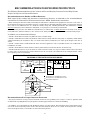
RECOMMENDATIONS FOR PROPER PROTECTION
The Following Recommendations for the Location of Fire and Burglary Detection Devices Help Provide
Proper Coverage for the Protected Premises.
Recommendations for Smoke and Heat Detectors
With regard to the number and placement of smoke/heat detectors, we subscribe to the recommendations
contained in the National Fire Protection Association's (NFPA) Standard #72 noted below.
• Early warning fire detection is best achieved by the installation of fire detection equipment in all rooms and areas of
the household as follows: For minimum protection a smoke detector should be installed outside of each separate sleeping
area, and on each additional floor of a multi-floor family living unit, including basements. The installation of smoke
detectors in kitchens, attics (finished or unfinished), or in garages is not normally recommended.
• For additional protection the NFPA recommends that you install heat
or smoke detectors in the living room, dining
room, bedroom(s), kitchen, hallway(s), attic, furnace room, utility and storage rooms, basements and attached garages.
In addition, we recommend the following:
• Install a smoke detector inside every bedroom where a smoker sleeps.
• Install a smoke detector inside every bedroom where someone sleeps with the door partly or completely closed. Smoke
could be blocked by the closed door. Also, an alarm in the hallway outside may not wake up the sleeper if the door is
closed.
• Install a smoke detector inside bedrooms where electrical appliances (such as portable heaters, air conditioners or
humidifiers) are used.
• Install a smoke detector at both ends of a hallway if the hallway is more than 40 feet (12 meters) long.
• Install smoke detectors in any room where an alarm control is located, or in any room where alarm control connections
to an AC source or phone lines are made. If detectors are not so located, a fire within the room could prevent the control
from reporting a fire or an intrusion.
THIS CONTROL COMPLIES WITH NFPA REQUIREMENTS FOR TEMPORAL PULSE
SOUNDING OF FIRE NOTIFICATION APPLIANCES.
DINING
KITCHEN
BEDROOM
BEDROOM
.
Smoke Detectors for Minimum Protection
Smoke Detectors for Additional Protection
Heat-Activated Detectors
BEDROOMBEDROOM
BEDROOM
BEDROOM
LIVING
ROOM
TV ROOM
DINING
LIVING ROOM
LIVING ROOM
BASEMENT
BEDROOMBEDROOM
BEDROOM
CLOSED
DOOR
GARAGE
KTCHN
KITCHEN
TO
BEDROOM
01000-002-V0
Recommendations For Proper Intrusion Protection
• For proper intrusion coverage, sensors should be located at every possible point of entry to a home or premises. This
would include any skylights that may be present, and the upper windows in a multi-level building.
• In addition, we recommend that radio backup be used in a security system. This will ensure that alarm signals can be
sent to the alarm monitoring station in the event that the telephone lines are out of order (alarm signals are normally
sent over the phone lines, if connected to an alarm monitoring station).

- 3 -
Table of Contents
SYSTEM FEATURES ..................................................................................................................................4
MOUNTING THE CONTROL.....................................................................................................................5
WIRING CONNECTIONS...........................................................................................................................6
CONNECTING/CONFIGURINGCOMMUNICATIONS DEVICES .........................................................8
AC POWER AND BACKUP BATTERY....................................................................................................11
INSTALLING WIRELESS ZONES...........................................................................................................13
MECHANICS OF PROGRAMMING ........................................................................................................16
ZONE RESPONSE TYPE DEFINITIONS ...............................................................................................18
DATA FIELD DESCRIPTIONS ................................................................................................................20
✻56 ENHANCED ZONE PROGRAMMING MODE ................................................................................29
✻80 DEVICE PROGRAMMING MENU MODE ......................................................................................34
✻81 ZONE LIST MENU MODE................................................................................................................37
✻83 ENHANCED SEQUENTIAL MODE ................................................................................................38
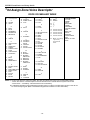
✻84 ASSIGN ZONE VOICE DESCRIPTORS ..........................................................................................41
✻85 RECORD CUSTOM VOICE DESCRIPTORS...................................................................................43
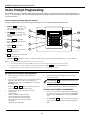
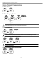
VOICE PROMPT PROGRAMMING.........................................................................................................44
REMOTE PROGRAMMING/CONTROL (DOWNLOADING) ................................................................48
SYSTEM OPERATION..............................................................................................................................50
TESTING THE SYSTEM ..........................................................................................................................56
SYSTEM COMMUNICATION ..................................................................................................................57
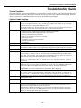
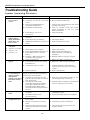
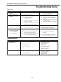
TROUBLESHOOTING GUIDE ................................................................................................................59
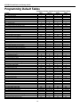
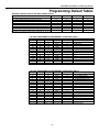
PROGRAMMING DEFAULT TABLES....................................................................................................62
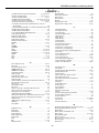
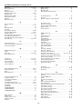
INDEX.........................................................................................................................................................65
REGULATORY AGENCY STATEMENTS ..............................................................................................68
LIMITATIONS OF THIS SYSTEM STATEMENT..................................................................................69
SPECIFICATIONS.....................................................................................................................................70
CONTACTING TECHNICAL SUPPORT.................................................................................................70
SUMMARY OF CONNECTIONS DIAGRAM ..........................................................................................71
WARRANTY ............................................................................................................................... Back Cover

LYNXR-I Installation and Setup Guide
- 4 -
System Features
U
UU
U
L
LL
L
LYNXR-I is not intended for UL985 Household Fire applications unless a 24-hour backup battery (P/N
LYNXRCHKIT-HC or LYNXRCHKIT-SHA) is installed.
Powerline Carrier Devices have not been evaluated by UL.
The LYNXR-I control is a self-contained, rechargeable wireless control/communicators that feature easy
installation and usage. A built-in speaker provides voice annunciation of system status along with voice
descriptors of each zone. An internal module (if provided) allows the LYNXR-I to communicate with the
Central Station via the Internet. The following illustration highlights the main features of this system.
AWAY
OFF
STAY
AUX
4
5
6
7
8
9
0
#
1
2
3
ZONES and DEVICES
• Up to 24 wireless zones
(5800 Series Transmitters)
• Up to 16 wireless button zones
• Up to 8 Powerline Carrier Devices
• Supports wireless keypads
8 USER CODES
• Installer code
• Master code
• 5 Secondary codes
• Duress code
• 3 Panic functions
ALARM OUTPUT
• Built-in sounder
• Piezo output
(30mA max.)
• Bell output
(120mA max.)
• Steady output for
burglary/panic
• Temporal pulse
output for fire alarms
• Long Range
Radio/Audio alarm
verification
PROGRAMMING
• Options stored in EEROM
• Can be uploaded, downloaded or
controlled via IBM-compatible
computer using Compass
downloader software and specified
HAYES modem
• Voice Prompt programming mode
COMMUNICATION
• Ademco Low Speed
• Sescoa/Radionics
• Ademco Express
• Ademco Contact ID
• Paging feature
• Internet Central
Station Communication
• GSM Cellular Central
Station Communication
SYSTEM POWER
• Primary Power: Ademco K10145X10
Plug-in Transformer, 110VAC to
9VAC, 25VA output (K10145CN in
Canada)
• Backup battery: Rechargeable
nickel-metal hydride battery pack
rated at 7.7Vdc.
FEATURES
• Real-time Clock display and Fixed-Word display
• Message Center (for user recorded messages)
• Voice announcement of system and zone status
• Voice chime
• Alarm Clock
• Reminder
• X-10 Scheduling
• Latch Key Reports
• Automatic Stay Arming
• Remote Phone Control
• “Follow Me” Reminder and System Announcements
OTHER FEATURES
• Exit error feature (detects difference between an
actual alarm and exit alarm caused by leaving a door
open after the exit delay expires)
• Event log stores up to 84 events
• Macro/ 1-button paging
• RF Jam Detection
• Remote Phone Control
• Compatible with Encrypted (High-Security) Devices
SPECIAL FEATURES
• Two-way voice communication
• Speaker phone operation

LYNXR-I Installation and Setup Guide
- 5 -
Mounting the Control
Wall Mounting
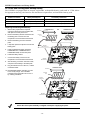
The illustration below shows the front assembly separated from the back plate.
DO NOT disconnect the ribbon cable from the terminal strip board. Disconnect the cable only from the
front assembly board.
1. Release the front assembly from the back
plate by depressing the two locking tabs
at the top of the unit with the blade of a
medium size screwdriver.
2. Once these tabs have been released,
insert the screwdriver in the side of the
case and release the side locking tabs by
gently twisting.
3. Carefully disconnect the ribbon cable from
the front assembly, leaving the ribbon
cable connected to the terminal block
PC board. The back plate contains the
terminal block for making wiring
connections.
4. Mount the back plate to a sturdy wall,
feeding the field wiring through the
appropriate openings in the back plate.
5. After wiring connections are made,
carefully reconnect the ribbon cable to
the front assembly PC board connector
(properly aligning the red wire).
6. Snap the front assembly to the back plate
so it is secured by the locking tabs.
LOCKING
TABS
LOCKING
TABS
LOCKING TABS
RED WIRE
MARKING
DISCONNECT
THIS END ONLY!
07000-003-V1
Desktop Mounting
For desktop use the optional mounting base (model LYNX-DM, purchased separately) must be used.
1. Slide the control panel onto the mounting
base locking tabs.
2. Bring all wiring through the bottom of the
mounting base, using one of the three
wire entry locations, before making
connections to the control panel.
3. Use tie-wraps to secure the wiring to the
built-in wire loops as needed. Use the two
supplied screws to secure the control
panel to the mounting base.
ADD
ESCAPE
DELETE
SELECT
AWAY
OFF
STAY
AUX
01009-004-V1
WIRE ENTRY
KNOCKOUT
(1 of 3)

LYNXR-I Installation and Setup Guide
- 6 -
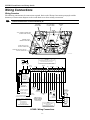
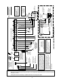
Wiring Connections
Wiring Overview
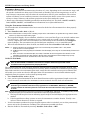
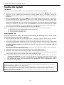
The following summarizes the connections required. Refer to the Wiring Connections paragraph and the
Summary of Connections diagram on the inside back cover when making connections.
U
UU
U
L
LL
L
External sounders have not been evaluated by UL.
07000-005-V1
7845i-L COMMUNICATIONS PORT
(INTERNAL MODULE ONLY)
ALARMNET LRR/IP
COMMUNICATION PORT
LOCAL SOUNDER
DISABLE JUMPER
TERMINAL
STRIP
TELEPHONE
CONNECTIONS
STANDARD AND HIGH CAPACITY
BATTERY CONNECTOR
SUPER HIGH CAPACITY
BATTERY CONNECTOR
INCOMING
PHONE
LINE
TO
HANDSET
PHONE
LINE
WARNING:
TO PREVENT
RISK OF SHOCK
DISCONNECT
TELEPHONE LINE
AT TELECOM
JACK BEFORE
SERVICING
THIS UNIT.
WEEKLY TESTING IS
REQUIRED TO ENSURE
PROPER OPERATION
OF THIS SYSTEM
ALL OUTPUT CIRCUITS ARE POWER LIMITED.
PREMISES
TELEPHONE
1
2
3
4
865
11
7
10
12
15
16
13
14
PHONE
FUTURE
USE
FUTURE
USE
SOUNDERS
PLCD
AC
EARTH
GROUND
EARTH
GROUND
INCOMING
TELEPHONE
LINE
RING
TIP
RING
TIP
( )
( )
(+)
(+)( )
PIEZO
6-14VDC
120mA max.
(e.g. WAVE2EX)
6-14VDC
30mA max.
DATA
OUT
SYNC
IN
POWERLINE
CARRIER DEVICES
RJ11
8
POS
JACK
AC
AC
SYNC
COM
DATA
9
BELL
07000-009-V1
NOTE
USE ONLY THE K10145X10
OR K10145CN
TRANSFORMERS PROVIDED
K10145X10
PLUG-IN
TRANSFORMER
9VAC, 25VA
X10
ONLY
CONNECTIONS
GND
DATA I N
GND
DATA OUT
LOCAL SOUNDER DISABLE
SHUNT REMOVE TO DISABLE
STANDARD/HIGH
CAPACITY BATTERY
CONNECTOR
SUPER HIGH CAPACITY
BATTERY CONNECTOR
ALARMNET LRR/IP
COMMUNICATIONS PORT
INTERNAL 7845i-L*
MODULE ONLY
THE LYNXR-I CONTROL IS COMPATIBLE WITH
THE FOLLOWING INTEGRAL RECHARGEABLE
BATTERY PACKS:
REPLACE EVERY FOUR YEARS
P/N LYNXRCHKIT-SC
P/N LYNXRCHKIT-HC
P/N LYNXRCHKIT-SHA
* WHEN AVAILBLE
UL NOTE
THE MINIMUM WIRE SIZE USED FOR TELEPHONE
INSTALLATIONS MUST BE #26 GAUGE
LYNXR-I Wiring Connections

LYNXR-I Installation and Setup Guide
- 7 -
Wiring Connections
1. Make Earth Ground Connection - The designated earth ground terminal (1) must be terminated in a good earth ground
for the lightning transient protective devices in this product to be effective. The following are examples of good earth
grounds available at most installations:
Metal Cold Water Pipe - Secure a non-corrosive metal strap (copper is recommended) to the pipe that is electrically
connected and secured to which the ground lead is electrically connected and secured.
AC Power Outlet Ground - Available from 3-prong, 120VAC power outlets only. To test the integrity of the ground
terminal, use a three-wire circuit tester with neon lamp indicators, such as the UL Listed Ideal Model 61–035, or
equivalent, available at most electrical supply stores.
a. Connect terminal 1 to a good earth ground.
2. Make Phone Line Connections - For local or full line seizure proceed to the appropriate steps below.
Local Seizure
a. Connect the incoming phone line to either the
8-position jack or terminals 2 (TIP) and 3
(RING) on the Lynx.
b. Connect the handset phone lines to either the
RJ11 jack or terminals 4 (TIP) and 5 (RING).
Full Line Seizure: The control must be
placed in series with the incoming phone
line. Plugging the Direct Connect Cord
directly into the RJ31X jack, allows the control
to seize the phone line when an alarm occurs
and normal phone line usage by the premises
phones if the plug needs to be removed.
c. Cut the incoming RING and TIP phone lines
(typically red and green, respectively) and
connect them to RJ31X terminals 4 (red) and
5 (green).
d. Connect the premises end of the cut RING
and TIP wires to RJ31X terminals 1 (grey) and
8 (brown) respectively.
e. Wire the flying leads of a Direct Connect Cord
to the control’s phone terminals as shown in
the diagram or plug into the 8-position jack.
f. Plug the Direct Connect Cord into the RJ31X
jack.
RJ31X
1
2
3
45
6
7
8
RING
TIP
INCOMING
PHONE LINE
TO
PREMISES PHONES
TIP RING TIP RING
BROWN
GREY
RED
GREEN
INCOMING
PHONE LINE
TO
PREMISES
PHONES
}
}
GREENRED
GREY
BROWN
RING
TIP
DIRECT
CONNECT
CORD
OR
OR
8-POSITION
JACK
01000-008-V0
Full Line Seizure Connections
U
UU
U
L
LL
L
Do not remove the local sounder shorting jumper (shunt).
External sounders and powerline carrier devices have not been evaluated by UL
LOCAL SOUNDER DISABLE: The Master Keypad’s built-in piezo sounder can be disabled by removing the
shorting jumper (shunt) on the terminal board. If disabled, however, no sounding will occur upon AC loss,
since the external sounder does not operate when AC power is lost.
3. Make External Sounder Connections - The control panel supports either a 6-14VDC piezo sounder (30mA max.) or
6-14VDC bell (120mA max.; e.g. ADEMCO WAVE2EX).
a. Connect a piezo sounder to terminals 10 (+) and 11 (–); OR a bell to terminals 11 (–) and 12 (+).
4. Disable Local Sounder Option - If required the Master Keypad’s built-in piezo sounder can be disabled.
a. Remove the shorting jumper (shunt) on the terminal board.
5. Make Powerline Carrier Device Connections - The control panel supports up to 8 Powerline Carrier Devices. If using
these devices, they must be connected to the K10145X10 transformer, as shown in the SUMMARY OF
CONNECTIONS diagram.
a. Connect the com/data/sync/ lines from the transformer to terminals 9, 13, and 14, respectively.
If not using the supplied connection cable, you may need to reverse the black and yellow wire connections.
Refer to the ✻
✻✻
✻80 Device Programming Menu Mode section for details on programming Powerline Carrier
Devices.

LYNXR-I Installation and Setup Guide
- 8 -
Connecting/Configuring Communication Modules
General
This LYNXR-I supports central station reporting via long range radio and internet. It also supports
upload/download programming capability via the Internet or a Private local area network (Intranet). This
allows site maintenance independent of central station monitoring, and modification to sites globally via the
Internet or through a private LAN. Refer to the instructions provided with the LRR/IP Communications
Device being installed for additional information regarding its installation, programming, and registration.
Zone 103 is the supervisory zone for the Communications Device.
LYNXR-I does not support the 7845i-ENT remote access feature.
Connecting Long Range Radio and Internet Communication Devices
Connect and configure the communications device as follows (refer to the Installation Instructions for device
that you are installing for additional information):
The wire run between the LYNXR-I and the Communications Device must not exceed ten (10) feet.
U
UU
U
L
LL
L
The 7845ENT and 7845CV2 have been evaluated by UL for Household Burglary installations. The
communications modules have not been evaluated for Household Fire installations.
AlarmNet 7845i-L* Communications Device
1. Install the module into the LYNXR-I back plate and secure it with the two provided screws. Refer to the diagrams below.
2. Connect the provided ribbon cable between the module and the PC board. This cable provides DC power and ground for
the module and data in/data out connections.
3. Connect the device to the Internet via a cable/DSL modem and router or to an Intranet (LAN) via the appropriate Ethernet
connection.
* When available. The 7845i-L module has not been evaluated by UL.
07000-004-V0
LRR / IP PORT
RJ45 (FOR INTERNET
CONNECTION)
COMMUNICATIONS
PORT FOR
INTERNAL 7845i-L
MODULE ONLY
7720P PROGRAMMER
CONNECTION
CABLE
Installing the 7845i-L Communications Module

LYNXR-I Installation and Setup Guide
- 9 -
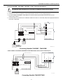
AlarmNet 7845GSM*, 7845i-GSM*, 7845i-ENT or 7845i, Communications Device
The 7845i-ENT/7845i and 7845CV2 can not be used for installations requiring 24-hour standby.
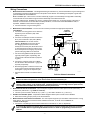
1. Connect the 4-wire communications cable to the LRR/IP Communications port on the LYNXR-I.
2. Connect the four wires to the specific Communications device as shown in the accompanying figures.
3. If you are installing a 7845GSM or 7845i-GSM you must also install a jumper between terminals 2 and 3 on the
communications device.
4. Connect the device to the Internet via a cable/DSL modem and router or to an Intranet (LAN) via the appropriate Ethernet
connection, if applicable.
7845GSM / 7845i-GSM
LYNX
SUPER HIGH
CAPACITY
BATTERY
(OPTIONAL)
REQUIRED FOR
24-HR BACKUP
7845i-GSM-010-V0
GND
Z3 OR DATA OUT
Z1/Z2 OR DATA IN
ECP (+) VOLTAGE INPUT
RED
BLK
GRN
YEL
RED
BLK
GRN
YEL
4
5
6
3
5
4
4-WIRE CABLE (N4632-4)
1
2
TB1
LRR/IP COMMUNICATIONS PORT
LYNXR-I CONTROL PANEL
NC
+12 VDC
GND
DATA I N
DATA OUT
LYNX
STANDARD
CAPACITY
BATTERY
Connecting AlarmNet 7845GSM* / 7845i-GSM*
* When available. The AlarmNet 7845GSM and 7845i-GSM modules have not been evaluated by UL.
7845i-ENT / 7845i
07000-013-V2
GND
DATA I N
DATA OUT
(+) VOLTAGE INPUT
RED
BLK
GRN
YEL
RED
BLK
GRN
YEL
TB 1
LYNXR-I CONTROL PANEL
NC
RED
BLK
GRN
YEL
+12 VDC
GND
DATA I N
DATA OUT
4-WIRE CABLE (N4632-4)
LYNX
STANDARD
CAPACITY
BATTERY
LRR/IP COMMUNICATIONS PORT
Connecting AlarmNet 7845i-ENT/7845i

LYNXR-I Installation and Setup Guide
- 10 -
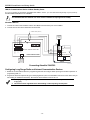
LRR/IP Communications Device 24-Hour Standby Power
If you are installing the AlarmNet 7845GSM/7845i-GSM or 7845i-L you must install the Super High Capacity battery
P/N WALYNX-RCHB-SHA in the LYNXR-I.
The 7845i-ENT/7845i and 7845CV2 can not be used for installations requiring 24-hour standby.
AlarmNet 7845CV2
1. Connect the 4-wire communications cable to the LRR/IP communications port on the LYNXR-I.
2. Connect the four wires to the 7845CV2 as shown below:
LRR/IP COMMUNICATIONS PORT
07000-011-V2
7845CV2
TB1
V+
GND
Z1/DATA IN
RAD FLT/ DATA OUT
P1 BAT
LYNXR-I CONTROL PANEL
RED
NC
BLK
GRN
YEL
RED
BLK
GRN
YEL
+12 VDC
GND
DATA I N
DATA OUT
4-WIRE CABLE (N4632-4)
LYNX
STANDARD
CAPACITY
BATTERY
BATTERY
ADEMCO
K4362
Connecting AlarmNet 7845CV2
Configuring Long Range Radio and Internet Communication Devices
1. Enable the communications device in programming field *55 and configure alarm reporting and module supervision in
programming field *77.
2. Program the device as required using the 7720P programmer (refer to the Installation Instruction for the device that you
are installing for additional information). Note that the device address must be set to 3.
1. When programming an AlarmNet 7845CV2 the radio’s “current limit” most option must be set
to [Y] (yes).
2. The device must be registered before downloading or alarm reporting can take place.

LYNXR-I Installation and Setup Guide
- 11 -
AC Power and Backup Battery
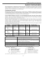
The system is powered by a 9VAC, 25VA Plug-in Transformer, ADEMCO K10145X10 (K10145CN in
Canada). Refer to the wiring table below for wire gauge and length.
Use only the provided ADEMCO K10145X10
or K10145CN Transformer.
Distance from Transformer
to Control
Wire Gauge
Up to 75 feet #20
75 to 150 feet #18
150 to 300 feet #16
Wiring to the AC Transformer must not exceed 300 feet using 16-gauge wire. The voltage reading
between terminals 15 and 16 of the control must not fall below 9.00VAC.
Do not plug the transformer into the AC outlet until after all wiring connections have been made.
Backup battery
In the event of an AC power loss, the system is supported by a long life backup battery that is supervised for
connection and for low voltage conditions. If the battery is missing, or a low battery condition is detected, a
“low battery” message is displayed and a report is sent to the central station. In addition, the system will beep
once every 45 seconds to audibly indicate a low battery condition (press any key to stop the beeping).
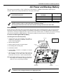
AC Power and Rechargeable Backup Battery
Connecting AC Power and backup battery
1. Connect wires from the K10145X10 (K10145CN) in
Canada) AC Transformer to terminals 15 and 16 as
shown in the wiring diagram.
2. Remove battery retainer.
3. Peel the backing from tape on the back plate.
4. Insert battery pack into back plate.
5. Install battery retainer.
6. Connect battery connector to receptacle on terminal
block PC board.
7. After all wiring connections have been made, snap the
front assembly to the back plate and plug the
transformer into a 24-hour, 110VAC unswitched outlet.
Note: Rechargeable batteries may take up to 48-hours to
fully charge. The “LOW BAT” message should clear
within four hours or by entering Test Mode.
BATTERY
PACK
07000-007-V0
BATTERY
RECEPTACLE
WIRING
TERMINALS
TAPE
RETAINER
NOTE
LYNXRCHKIT-HC
BATTERY PACK SHOWN
Ensure the cover is snapped closed prior to applying AC power.

LYNXR-I Installation and Setup Guide
- 12 -
AC Power and Rechargeable Backup Battery
The LYNXR-I is equipped with an integral, replaceable, rechargeable battery pack rated at 7.7Vdc. Select
the appropriate battery pack, based on the installation’s requirement, and install the battery pack.
Model/Part Number
Battery StandbyTime Low Battery Notification
LYNXRCHKIT-SC 4-hours (minimum) Approximately 1-hour before battery depletion
LYNXRCHKIT-HC 24-hours (minimum) At least 1-hour before battery depletion
LYNXRCHKIT-SHA 24-hours (minimum) At least 1-hour before battery depletion
Replacing the Rechargeable Battery
1. When battery replacement is required,
unplug the transformer from the wall outlet,
and open the control panel cover.
2. Remove the battery retainer and disconnect
the battery pack connector from the
receptacle on the terminal block PC board.
3. Remove the battery pack from the back
plate.
4. If required, replace the tape that secures the
battery pack.
5. Install a replacement battery pack (P/N
LYNXRCHKIT-SC, LYNXRCHKIT-HC or
LYNXRCHKIT-SHA) into the back plate.
6. Install the battery retainer.
7. Connect the battery connector to the
receptacle on the terminal block PC board.
8. After the wiring connection has been made,
snap the front assembly to the back plate.
9. Plug the transformer into a 24-hour, 110VAC
unswitched outlet.
10. Rechargeable batteries may take up to 48-
hours to fully charge. The “LOW BAT”
message should clear within four hours or
by entering Test Mode.
07000-006-V1
LYNXRCHKIT-SHA
RETAINER
BATTERY
CONNECTOR
BATTERY
PACK
TAPE
BATTERY
RECEPTACLE
LYNXRCHKIT-HC OR LYNXRCHKIT-SC
RETAINER
BATTERY
CONNECTOR
BATTERY
PACK
TAPE
BATTERY
RECEPTACLE
Ensure the control panel assembly is snapped closed prior to applying AC power.

LYNXR-I Installation and Setup Guide
- 13 -
Installing Wireless Zones
General Information
Zones: The control supports up to 24 wireless zones using 5800 Series transmitters, and up to 16 wireless
buttons.
Range: The built-in RF receiver can detect signals from wireless transmitters within a nominal range of 200
feet.
Transmitters: 5800 Series transmitters have built-in serial numbers that must be entered into the system
using the ✻56 or ✻83 interactive mode, or input to the control via the downloader. 5800 Series transmitters
(except the 5800RL, which is described separately) do not have DIP switches. Each transmitter's zone
number is programmed into the system in ✻56 mode. Some transmitters, such as the 5816 and 5817, can
support more than one "zone" (referred to as loops or inputs). On the 5816, for example, the wire connection
terminal block is loop 1, the reed contact is loop 2. Each loop must be assigned a different zone number.
U
UU
U
L
LL
L
The 5816 and 5817 Transmitters do not have EOL supervision of their loop wiring and the loop wiring must
not exceed 3 feet.
The 5800RL, 5802MN, 5802MN2, 5804, 5804BD, 5804BDV, 5804E, 5814, 5816TEMP, 5819, 5819S(WHS &
BRS), 5828/5828V and 5850(GBD) transmitters have not been evaluated by UL.
For button transmitters (RF "keys") such as the 5804 and 5801, you must assign a unique zone number to
each individual button used on the transmitter. Each button on the transmitter also has a pre-designated
loop or input number, which is automatically displayed.
House Identification
If you are using a 5804BD/5804BDV Wireless Keypad with the system, you must program a House ID Code
(01–31) in field ✻24 to establish proper communication, and the keypad must be set to the same ID. House
ID 00 disables all wireless keypads. An RF House ID is not necessary for other 5800 Series transmitters; the
entry should be left at “00” (default) in those cases.
Transmitter Supervision
Except for some transmitters/keypads that may be carried off-premises (5804, 5804BD, 5804BDV, and
5804E), each transmitter is supervised by a check-in signal that is sent to the receiver at 70–90 minute
intervals. If at least one check-in is not received from each supervised transmitter within a 12-hour period,
the "missing" transmitter number(s) and "FAULT" will be displayed. The supervision for a particular
transmitter in the system that may also be carried off the premises (5801, 5802MN) may be turned off by
entering it as a "UR" (unsupervised RF) type, as described in the ✻56 Enhanced Zone Programming Mode
section.
5800 Series transmitters have built-in tamper protection and will annunciate as a fault condition if covers
are removed.
Transmitter Input Types
Each of the following transmitters has one or more unique factory-assigned input (loop) ID codes. Each of the
inputs requires a programming zone
(e.g., a 5804's four inputs require four button zones).
Transmitters can be entered as one of the following types
(see transmitter’s instructions for appropriate input
type)
:
Type Description
"RF" (Supervised RF) Sends periodic check-in signals, as well as fault, restore, and low battery signals.
The transmitter must remain within the receiver's range.
"UR" (Unsupervised RF) Sends all the signals that the "RF" type does, but the control does not supervise the
check-in signals. The transmitter may therefore be carried off-premises.
"BR" (Unsupervised Button RF) These only send fault signals. They do not send low battery signals until they are
activated. The transmitter may be carried off-premises.

LYNXR-I Installation and Setup Guide
- 14 -
Transmitter Battery Life
• Batteries in the wireless transmitters may last from 4–7 years, depending on the environment, usage, and
the specific wireless device being used. Factors such as humidity, high or low temperatures, as well as
large swings in temperature may all reduce the actual battery life in a given installation. The wireless
system can identify a true low battery situation, thus allowing the dealer or user of the system time to
arrange a change of battery and maintain protection for that point within the system.
• Button-type transmitters should be periodically tested for battery life. The 5801, 5802MN, 5802MN2,
5804, 5804BD, 5804BDV, and 5804E button transmitters have replaceable batteries.
Using the Transmitter Sniffer Mode
Use this mode after all transmitters have been entered to check that all transmitters have been properly
programmed.
1. Enter Installer code (4112) + [#] + 3.
Note: If the communicator is in the process of sending a report to the central station, the system will not go into the Sniffer
mode. If so, wait a few minutes and try again.
2. The keypad will display all zone numbers, which have a non-zero Zone Type (even if serial numbers were
not learned yet). Fault each transmitter in turn, causing each one to send a signal. As the system
receives a signal from each of the transmitters, the zone number of that transmitter will disappear
from the display. The transmitters may be checked upon installation, or in an installed system.
3. When all transmitters have been checked, exit Sniffer mode. Enter Installer Code (4112) + OFF.
Notes: (1) Sniffer mode does not automatically expire. You must manually exit (Installer Code + OFF) Sniffer
mode to return to normal operation.
(2) All BR-type units must physically be activated to clear the display, since they do not automatically send check-in
signals.
(3) When one button of a transmitter (RF, UR, or BR) is activated, all zones assigned to other buttons on that
transmitter are cleared. This also applies to 5816 and 5817 transmitters that have multiple loops (zones).
(4) Any transmitter that is not “entered” will not turn off its zone number.
Go/No Go Test Mode
5804E encrypted (High-Security) devices must be activated while the system is in Go/No Go Test Mode.
Refer to the transmitter’s installation instructions for complete details. The system will confirm
enrollment of the encrypted device by beeping two times.
The Go/No Go tests will verify adequate RF signal strength from the proposed transmitter location, and
allow you to reorient or relocate transmitters if necessary, before mounting the transmitters permanently.
This mode is similar to the transmitter Test mode, except that the wireless receiver gain is reduced. This
will enable you to make sure that the RF signal from each transmitter is received with sufficient signal
amplitude when the system is in the normal operating mode.
1. Enter Installer Code (4112) + [#] + 8.
2. Once you have placed transmitters in their desired locations and the approximate length of wire to be
run to sensors is connected to the transmitter's screw terminals (if used), fault each transmitter.
Conducting this test with your hand wrapped around the transmitter will cause inaccurate results.
On button type transmitters that have been programmed to set ARM AWAY, ARM STAY, or DISARM,
pressing a button will take the system out of the Go/No Go Test mode and cause the programmed action
to occur.
Note: On button type transmitters that have been programmed to set ARM AWAY, ARM STAY, or DISARM, pressing a button
will take the system out of the Go/No Go Test mode and cause the programmed action.
a. The keypad will beep three times indicating signal reception and will display the appropriate zone
number.
b. If the keypad does not beep, reorient or move the transmitter to another location. Usually a few
inches in either direction is all that is required.
3 If each transmitter produces the proper keypad response when it is faulted, you can then permanently
mount each of the transmitters according to the instructions provided with them.
4 Exit the Go/No Go Test mode by entering: Installer Code (4112) + OFF.

LYNXR-I Installation and Setup Guide
- 15 -
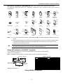
5800 Series Transmitter Loop Numbers (Refer to this information when programming transmitters)
The following illustration shows the compatible transmitters, their associated input types and loop
designations.
LOOP 1
5806/5807/5808/5808LST
ENROLL AS
"RF"
LOOP 1
5809
ENROLL AS
"RF"
5818
ENROLL AS
"RF"
LOOP 1
LOOP 1
5814
ENROLL AS
"RF"
01009-012-V4
5828/5828V
PROGRAM
HOUSE ID
LOOP 1
(MOTION)
5890/5890PI
ENROLL AS
"RF"
LOOP
1
5802 MN
ENROLL AS
"UR" OR "RF"
5804BD/5804BDV
ENROLL AS
"BR"
PROGRAM HOUSE ID
LOOP 4
YOU MUST
ENROLL
THIS BUTTON
LOOP 3
LOOP 1
LOOP 2
•
•
•
•
•
•
•
•
•
•
•
•
•
•
•
•
•
•
•
5804/5804E
ENROLL AS "BR"
LOOP 1
LOOP 2
LOOP 4
YOU MUST
ENROLL
THIS
BUTTON
O
F
F
LOOP 3
O
N
5816TEMP
ENROLL AS
"RF"
LOOP 1
(TEMP
SENSOR)
5817
ENROLL AS
"RF"
LOOP 2
(AUX.
CENTER)
LOOP 1
(PRIMARY)
LOOP 3
(AUX.
RIGHT)
5816
ENROLL AS
"RF"
LOOP 1
(TERMINALS)
LOOP 2
(REED)
5816MN
ENROLL AS
"RF"
LOOP 1
(TERMINALS)
ALTERNATE
POSITION
FOR LOOP 2
LOOP 2
(REED)
LOOP 3
(TERMINALS)
5819S (WHS & BRS)
ENROLL AS
"RF"
LOOP 1
(INTERNAL
SHOCK
SENSOR
LOOP 2
(REED)
5819
ENROLL AS
"RF"
LOOP 2
(REED)
LOOP 3
(TERMINALS)
LOOP 1
(TERMINALS)
5800WAVE
PROGRAM
HOUSE ID
5800RL
SET
HOUSE ID
5801
ENROLL AS
"UR" OR "RF"
LOOP 3
LOOP 1
LOOP 2
LOOP 4
YOU MUST
ENROLL
THIS
BUTTON
5849
ENROLL AS
"RF"
LOOP 1
(SOUND)
5802 MN2
ENROLL AS
"UR" OR "RF"
LOOP
1
5850 (GBD)
ENROLL AS
"RF"
(Green)
(Red)
(Yellow)
ARMED
READY
Notes: (1) Loop 4 must be enrolled on the 5801, 5804, 5804BD, 5804BDV and 5804E transmitters, whether or not the loop
is used.
(2) 5804E encrypted (High-Security) devices must be activated while the system is in Go/No Go Test Mode. Refer
to the transmitter’s installation instructions for complete details. The system will confirm enrollment of the
encrypted device by beeping two times.
U
L
The 5800RL, 5802MN, 5802MN2, 5804, 5804BD, 5804BDV, 5804E, 5814, 5816TEMP, 5819, 5819S(WHS & BRS),
5828/5828V and 5850(GBD) wireless transmitters
have not been evaluated by UL.
Setting DIP Switches on the 5800RL Transmitter
Set the 5800RL Transmitters to the programmed House ID, by using the DIP switches.
(OFF position is indicated by ---)
Note: The 5800RL cannot be used in conjunction with the Auto Arm (scheduled arming) feature.
01000-014-V1
234561
SW-6 SETS
MODE
2-6 SETS HOUSE ID
SW-1 ACTIVATES
MODE SETTING
SWITCH DOWN
FOR "OFF"
SHOWN SET FOR HOUSE ID# 12
SWITCH UP FOR "ON"
5800RL DIP SWITCH TABLE
DIP SWITCH POSITIONS DIP SWITCH POSITIONS House
ID
2 3 4 5 6
House
ID
2 3 4 5 6
0 --- --- --- --- --- 16 ON --- --- --- ---
1 --- --- --- --- ON 17 ON --- --- --- ON
2 --- --- --- ON --- 18 ON --- --- ON ---
3 --- --- --- ON ON 19 ON --- --- ON ON
4 --- --- ON --- --- 20 ON --- ON --- ---
5 --- --- ON --- ON 21 ON --- ON --- ON
6 --- --- ON ON --- 22 ON --- ON ON ---
7 --- --- ON ON ON 23 ON --- ON ON ON
8 --- ON --- --- --- 24 ON ON --- --- ---
9 --- ON --- --- ON 25 ON ON --- --- ON
10 --- ON --- ON --- 26 ON ON --- ON ---
11 --- ON --- ON ON 27 ON ON --- ON ON
12 --- ON ON --- --- 28 ON ON ON --- ---
13 --- ON ON --- ON 29 ON ON ON --- ON
14 --- ON ON ON --- 30 ON ON ON ON ---
15 --- ON ON ON ON 31 ON ON ON ON ON
Setting 5800RL DIP Switches

LYNXR-I Installation and Setup Guide
- 16 -
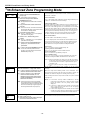
Mechanics of Programming
General Programming Information
Programming options are stored in non-removable, electrically erasable, nonvolatile EEROM memory. The
system can be programmed at any time, even at the installer's premises prior to the actual installation.
Simply apply power temporarily to the Control and then program the unit as desired. There are four
programming modes:
• Data field programming (used for setting various system options).
• Interactive menu mode programming (used for programming zone information, programming
Powerline Carrier Devices, and for entering transmitter serial numbers).
• Voice Prompt programming (used for setting various system options).
• Pass-Thru programming (used for programming connected LRR/IP Communications Device).
The system can also be programmed remotely, using an IBM Personal Computer, a modem, and Compass
Downloader for Windows. See the Remote Programming/Control (Downloading) section.
Note: You may find it convenient to adjust the volume setting before entering the Program Mode. This will allow you to
clearly hear the feedback announcements or system beeps in the Programming Mode, of the system’s built-in
speaker. To adjust the volume, press FUNCTION + VOLUME+ [3] or [6]. Upon exiting the Program Mode, the
system will reset the volume to the default value (mid level).
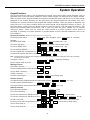
Entering Program Mode
Use one of the following methods to enter Programming Mode:
1. Press both the [✻] and [#] keys at the same time, within 50 seconds after power is applied to the
Control or from exiting Programming mode, OR
2. After power-up, enter the Installer Code (4112) + 800 to enter Expert Programming mode (This
method disabled if Program mode is exited using ✻98). OR enter Installer Code (4112) + 888 to
enter Voice Prompt Programming mode.
If a different Installer Code has been programmed, use that code to enter the Programming mode.
3. Upon entering programming mode, the control will display “--” for up to two seconds indicating it is
communicating with the LRR/IP devices.
4. Once you have entered the Program mode, data field “20” (the first data field in the system) will be displayed and
both keypad LEDs will flash. If you have entered the Voice Prompt Programming mode. “Pro” will be displayed.
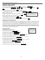
Programming a Data Field
1. Press [✻] + Field No. (for example, ✻21), followed by the required entry.
2. When you have completely programmed a data field, the keypad will “beep” three times and then
automatically display the next data field in sequence. To go to a different field, press [✻] plus the
desired field number.
3. If the number of digits that will be entered in a data field is less than the maximum number of digits
available (e.g. phone number field), enter the desired data, then press [✻] to advance to the next data
field.
4. If a nonexistent field has been entered, the keypad will display “EE”. Simply re-enter [✻] plus a valid
field number.
To view a data field without making changes:
Enter [#] + Field No. Data will be displayed for that field.
To delete an entry in a field:
Enter [✻] + Field No. + [✻]. (Applies only to fields ✻40–✻44, ✻88 and ✻94).

LYNXR-I Installation and Setup Guide
- 17 -
Interactive Menu Mode Programming (✻56, ✻80, ✻81, ✻83, ✻84, ✻85)
Press
[✻] + interactive mode No. (i.e., ✻56). The keypad will display the first of a series of prompts. A detailed
procedure (with displays of prompts) is provided in later sections of this manual.
Interactive Mode Used to Program
✻
56 Enhanced Zone Programming Mode
Zone characteristics, report codes, and serial numbers
✻80 Device Programming Menu Mode Powerline Carrier Devices
✻81 Zone List Menu Mode Zone Lists for powerline carrier activation
✻
83 Enhanced Sequential Mode
5800 Series transmitter serial numbers
✻84 Assign Zone Voice Descriptors Voice descriptors for each zone
✻85 Record Custom Voice Descriptors Up to 5 custom voice descriptors for zones
Loading Factory Defaults
To load the factory defaults, enter the Programming mode, press ✻97, then press number 1, 2, 3, or 4 to
select from default tables
1-4 at the back of this manual, or press “0” if you are not selecting a default table.
If a default table is loaded, any data that has already been programmed into the system will be changed according to the
default table selected!
✻96 resets all subscriber account numbers and CSID in preparation for an initial download.
Exiting Program Mode
✻98 inhibits re-entry into the Expert or Voice Prompt Programming modes using the Installer Code.
✻99 allows re-entry into the Expert Program mode using Installer Code (4112) + 800 or into the Voice
Prompt Programming mode using Installer Code (4112) + 888.
Note: After exiting program mode (or upon power-up), the system takes up to a minute to reset. To bypass the reset
delay, press [#] + [0].
Pass-Thru Programming
This mode allows the Installer to use the LYNXR-I keypad and display to program the communications
device that is connected to the LYNXR-I. Refer to the communications device’s installation instruction to
determine whether this feature is supported.
Entering Pass-Thru Programming mode
1. After power-up, enter the Installer Code (4112) + 899.
2. Once you have entered Pass-Thru Programming mode “PtP” will be displayed on the keypad.
3. Refer to the Installation Instructions for the LRR/IP Communications Device being installed for
additional programming information.
LYNXR-I will abort this mode:
• When it receives an abort command from the new communications device.
• If it fails to communicate with an communications device after 20 attempts.
• 30 minutes after the last key has been pressed.

LYNXR-I Installation and Setup Guide
- 18 -
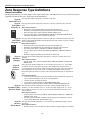
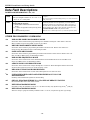
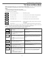
Zone Response Type Definitions
General Information
During programming, you must assign a zone type to each zone, which defines the way in which the system
responds to faults in that zone. Zone types are defined below.
Type 00
Zone Not Used
Zone type 00 is used to program a zone that is not used.
Type 01
Entry/Exit
Burglary #1
01000-017-V0
Zone type 01 is usually assigned to sensors or contacts on primary entry and exit
doors.
Zone Characteristics:
• Entry delay #1 is programmable from 0-99 seconds (field
✻35).
• Exit delay is independently programmable from 0-99 seconds (field
✻34).
• Exit and entry delays when armed in AWAY or STAY mode.
• No entry delay when armed in STAY NO DELAY or AWAY NO DELAY mode.
• Exit delay regardless of the arming mode selected.
Type 02
Entry/Exit
Burglary #2
01000-017-V0
Zone type 02 is usually assigned to sensors or contacts on which secondary entry and
exit doors that might be further from the keypad (typically used for a garage, loading
dock, or basement door).
Zone Characteristics:
• Entry delay #2 is programmable from 0-99 seconds (field
✻36).
• Exit delay is independently programmable from 0-99 seconds (field
✻34).
• Secondary entry delay, if armed in the AWAY or STAY mode.
• No entry delay when armed in the STAY NO DELAY or AWAY NO DELAY
mode.
• Exit delay begins regardless of the arming mode selected.
01000-018-V0
Type 03
Perimeter
Burglary
Zone type 03 is usually assigned to all sensors or contacts on exterior doors and
windows.
Zone Characteristics:
• Instant alarm, when armed in AWAY, STAY, STAY NO DELAY, or AWAY NO
DELAY mode.
Type 04
Interior,
Follower
5890 / 5890PI
01000-019-V1
Zone type 04 is usually assigned to a zone covering an entry area (i.e.: foyer, lobby,
or hallway) that one must pass upon entry (after faulting the entry/exit zone) to
reach the keypad. It provides an instant alarm if the entry/exit zone is not violated
first, and protects an area in the event an intruder has hidden on the premises
before the system is armed, or gains access to the premises through an unprotected
area.
Zone Characteristics:
• Delayed alarm (using the programmed entry/exit time) if entry/exit (types 01 or
02) or interior-with-delay (type 10) zone is faulted first.
• Instant alarm in all other situations.
• Active when armed in AWAY or AWAY NO DELAY mode.
• Bypassed automatically when armed in STAY or STAY NO DELAY mode.
Type 05
Trouble by Day/
Alarm by Night
Zone type 05 is usually assigned to a zone that contains foil-protected doors or
windows or covers a sensitive area (i.e.: stock room, drug supply room, etc.) It can
also be used on a sensor or contact in an area where immediate notification of an
entry is desired.
Zone Characteristics:
• Instant alarm, when armed in AWAY, STAY, STAY NO DELAY, or AWAY NO
DELAY (night) mode.
• Provides a latched trouble sounding from the keypad and, if desired, a central
station report during the disarmed state (day).
Type 06
24-hour
Silent Alarm
Zone type 06 is usually assigned to a zone containing an Emergency button (silent
emergency).
Zone Characteristics:
• Sends a report to the central station but provides no keypad display or sounding.

LYNXR-I Installation and Setup Guide
- 19 -
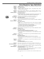
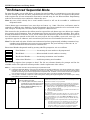
Zone Response Type Definitions
Type 07
24-hour
Audible
Alarm
Zone type 07 is usually assigned to a zone containing an Emergency button
(audible emergency).
Zone Characteristics:
• Sends a report to the central station, and provides alarm sounds
externally and at the keypad.
Type 08
24-hour
Auxiliary Alarm
Zone type 08 is usually assigned to a zone containing a button for use in
personal emergencies or to a zone containing monitoring devices (i.e.: water
or temperature sensors, etc.).
Zone Characteristics:
• Sends a report to the central station and provides an alarm sound at the
keypad. (No bell output is provided and there is no keypad timeout.)
5806/5807/5808
01000-020-V0
Type 09
Supervised
Fire
Zone type 09 can be assigned to any wireless zone used as a fire
zone. This zone type is always active and cannot be bypassed.
Zone Characteristics:
• Bell output will pulse when this zone type is alarmed.
Type 10
Interior w/Delay
Zone type 10 is bypassed when the panel is armed in the STAY or STAY NO
DELAY mode.
Zone Characteristics:
• Entry delay #1 (with programmed entry time) when armed in the AWAY
mode.
• Entry delay begins whenever sensors in this zone are violated, regardless
of whether an entry/exit delay zone was tripped first.
• No entry delay when armed in the AWAY NO DELAY mode.
• Exit delay regardless of the arming mode selected.
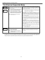
Type 20
Arm–Stay
Zone type 20 is a special-purpose zone type used with 5800 Series wireless
pushbutton units.
Zone Characteristics:
• Exit delay regardless of the arming mode selected.
• System is armed in the STAY mode when the zone is activated.
• Zone number is sent to the central station as a user number when arming
or disarming.
Type 21
Arm–Away
Zone type 21 is a special-purpose zone type used with 5800 Series wireless
pushbutton units.
Zone Characteristics:
• System is armed in the AWAY mode when the zone is activated.
• Zone number is sent to the central station as a user number when arming
or disarming.
Type 22
Disarm
Zone type 22 is a special-purpose zone type used with 5800 series wireless
pushbutton.
Zone Characteristics:
• Disarms the system when the zone is activated.
Type 23
No Alarm Response
Zone type 23 can be used on a zone when a Powerline Carrier Device (e.g.,
X10) action is desired, but with no accompanying alarm (e.g., front door light).
Type 24
Silent Burglary
Zone type 24 is usually assigned sensors or contacts on exterior doors and
windows where bells and/or sirens are NOT desired.
Zone Characteristics:
• Instant alarm, with NO audible indication when is armed in the AWAY,
STAY, STAY NO DELAY, or AWAY NO DELAY mode.
• Report sent to the central station.
Note: Keypad beeps if the zone is faulted when system is disarmed and Chime mode is
on.

LYNXR-I Installation and Setup Guide
- 20 -
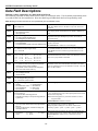
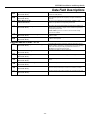
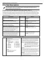
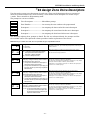
Data Field Descriptions
Defaults (where applicable) are Indicated in bold text.
The following pages list all data fields in this Control (in numerical order). Use the blank programming form
to record the data for this installation. Note that both keypad LEDs flash while in Programming mode.
Note: Entering a number other than the one specified will give unpredictable results.
✻
20
Installer Code
Enter 4 digits, 0-9
The Installer Code is used to enter the 4-digit Master Security
Code. See "Master Code" in the System Operation section for
procedure.
✻21
Quick Arm Enable
0 = do not allow quick arm
1 = allow quick arm
If enabled, security code is not required to arm the system. The
user simply presses and holds down the AWAY or STAY key to
arm.
✻22
Keypad Backlight Timeout
0 = no timeout; always backlight keys
1 = turn backlighting off after inactivity
This option allows the choice of either always backlighting the
keypad or turning the backlighting off after 10 seconds of
keypad inactivity.
✻23
Forced Bypass
0 = no forced bypass
1 = provide automatic bypass of all open (faulted) zones
All zones bypassed by this function will be displayed after the
bypass is initiated.
UL installations: must be 0 (no forced bypass)
✻24
RF House ID Code
00 = disable all wireless keypad usage
01-31 = House ID
The House ID identifies receivers and wireless keypads.
If a 5804BD/5804BDV Transmitter is to be used, a House ID
Code MUST be entered, and the keypad should be set to the
same ID.
✻25
Powerline Carrier Device (X10) House ID
0 = A 4 = E 8 = I # + 12 = M
1 = B 5 = F 9 = J # + 13 = N
2 = C 6 = G # + 10 = K # + 14 = O
3 = D 7 = H # + 11 = L # + 15 = P
Powerline Carrier Devices require a House ID. This field
identifies this House ID to the Control. The Powerline Carrier
Devices are programmed in field ✻80.
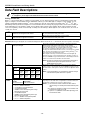
✻26
Chime by Zone
0 = no (chimes on fault of any entry/exit or perimeter
zone when Chime mode is activated
1 = yes (chimes on fault of those zones assigned to
Zone List 3 when Chime mode on)
This option allows the installer to define the specific zones
intended to chime when faulted while the system is in Chime
mode. If enabled, these zones are defined in zone list 3 (see ✻81
Zone List Menu Mode).
✻27
Real Time Clock Display
0 = do not display the time
1 = display the time
Refer to the User’s Manual for setting the clock time and date.
✻29
Daylight Savings Time Start/End Month
0, 0 = no daylight saving time used
1-12 = start month and end month
Enter # + 10 for 10, # + 11 for 11, and # + 12 for 12.
✻30
Daylight Savings Time Start/End Week
0 = disable 4 = fourth weekend
1 = first weekend of month 5 = last weekend
2 = second weekend 6 = next to last
3 = third weekend 7 = 3
rd
from last
Enter the appropriate start and end weekend of the month.
✻31
Single Alarm Sounding Per Zone
(per armed period)
0 = no limit on alarm sounding per zone
1 = limit alarm sounding to once per arming period for
a given zone
This field applies only to burglary zones (zone response types 1-
5, 10), and affects long range radio reporting but does not affect
central station reporting.
Note: This field applies only to the bell and does not affect
keypad sounds.
UL installations: must be 0 (no limit)
✻32
Fire Sounder Timeout
0 = yes, fire sounder timeout after time programmed in
field
✻33
1 = no fire sounder timeout; continue sounding until
manually turned off
This Control complies with NFPA requirements for temporal
pulse sounding of fire notification appliances.
Temporal pulse sounding for a fire alarm consists of the
following: 3 pulses – pause – 3 pulses – pause – 3 pulses. . .
✻33
Alarm Bell Timeout
0 = No timeout 2 = 8 min 4 = 16 min
1 = 4 min 3 = 12 min
This field determines whether the external sounder will shut
off after time allowed, or continue until manually turned off.
UL installations: must be set for a minimum of 4 min
(option 1)
Page is loading ...
Page is loading ...
Page is loading ...
Page is loading ...
Page is loading ...
Page is loading ...
Page is loading ...
Page is loading ...
Page is loading ...
Page is loading ...
Page is loading ...
Page is loading ...
Page is loading ...
Page is loading ...
Page is loading ...
Page is loading ...
Page is loading ...
Page is loading ...
Page is loading ...
Page is loading ...
Page is loading ...
Page is loading ...
Page is loading ...
Page is loading ...
Page is loading ...
Page is loading ...
Page is loading ...
Page is loading ...
Page is loading ...
Page is loading ...
Page is loading ...
Page is loading ...
Page is loading ...
Page is loading ...
Page is loading ...
Page is loading ...
Page is loading ...
Page is loading ...
Page is loading ...
Page is loading ...
Page is loading ...
Page is loading ...
Page is loading ...
Page is loading ...
Page is loading ...
Page is loading ...
Page is loading ...
Page is loading ...
Page is loading ...
Page is loading ...
Page is loading ...
Page is loading ...
-
 1
1
-
 2
2
-
 3
3
-
 4
4
-
 5
5
-
 6
6
-
 7
7
-
 8
8
-
 9
9
-
 10
10
-
 11
11
-
 12
12
-
 13
13
-
 14
14
-
 15
15
-
 16
16
-
 17
17
-
 18
18
-
 19
19
-
 20
20
-
 21
21
-
 22
22
-
 23
23
-
 24
24
-
 25
25
-
 26
26
-
 27
27
-
 28
28
-
 29
29
-
 30
30
-
 31
31
-
 32
32
-
 33
33
-
 34
34
-
 35
35
-
 36
36
-
 37
37
-
 38
38
-
 39
39
-
 40
40
-
 41
41
-
 42
42
-
 43
43
-
 44
44
-
 45
45
-
 46
46
-
 47
47
-
 48
48
-
 49
49
-
 50
50
-
 51
51
-
 52
52
-
 53
53
-
 54
54
-
 55
55
-
 56
56
-
 57
57
-
 58
58
-
 59
59
-
 60
60
-
 61
61
-
 62
62
-
 63
63
-
 64
64
-
 65
65
-
 66
66
-
 67
67
-
 68
68
-
 69
69
-
 70
70
-
 71
71
-
 72
72


Honeywell K14114 User manual
- Category
- Security access control systems
- Type
- User manual
- This manual is also suitable for
Ask a question and I''ll find the answer in the document
Finding information in a document is now easier with AI
Related papers
-
Honeywell LYNXR-2 Series Security System Programming Manual
-
-
-
-
-
-
-
Honeywell LYNX Touch L7000 Series Quick Manual
-
Honeywell ADEMCO 5800RL Installation guide
-
Other documents
-
DSC WLS900 User manual
-
 Apxalarm APX32 User manual
-
 Apxalarm APX32 User manual
-
First Alert ReadyGuard Plus User manual
-
ADEMCO LYNX User manual
-
-
 Apxalarm APX32EN Quick start guide
-
-
-


