Page is loading ...

Mainboard User’s Manual
This publication, photographs, illustrations and software are under
the protection of international copyright laws and all rights
reserved. It does not allow any reproduction of this manual, content
and any materials contained herein without the written consent of
the authentic manufacturer.
The information in this manual is subject to change without notice.
The manufacturer does neither represent nor warrant the contents
hereof; and specifically disclaims any implied warranties of
merchantability or fitness for any particular purpose. Furthermore,
the manufacturer reserves the right to revise and change this
publication from time to time, without the obligation of notifying
any person of such revision or changes.
Trademarks
IBM, VGA, and PS/2 are registered trademarks of International
Business Machines.
Intel, Pentium, Pentium-II, Pentium-III, Pentium-IV, MMX,
Celeron and Tualatin are registered trademarks of Intel Corporation.
Microsoft, MS-DOS and Windows 95/98/NT/2000 are registered
trademarks of Microsoft Corporation.
PC-cillin is a trademark of Trend Micro Inc.
Award is a trademark of Award Software Inc.
A3D is a registered trademark of Aureal Inc.
SuperVoice is a registered trademark of Pacific Image
Communications Inc.
MediaRing Talk is a registered trademark of MediaRing Inc.
3Deep is a registered trademark of E-Color Inc.
Other names used in this publication may be trademarks and are
acknowledged.
Copyright © 2001
All Rights Reserved
MS7188D Series, V5.2
V8601T/December 2001

Mainboard User’s Manual
II

Mainboard User’s Manual
III
Table of Contents
Trademarks ..............................................................................I
Chapter 1......................................................................................... 1
Introduction................................................................................. 1
Key Features........................................................................... 2
Package Contents.................................................................... 4
Static Electricity Precautions.................................................. 5
Pre-Installation Inspection...................................................... 5
Chapter 2......................................................................................... 7
Mainboard Installation ................................................................ 7
Mainboard Components.......................................................... 8
I/O Ports.................................................................................. 9
Install A CPU.......................................................................... 9
Install Memory...................................................................... 11
Setting Jumper Switches....................................................... 12
Install the Mainboard............................................................ 15
Optional Extension Brackets................................................. 17
Install Other Devices ............................................................ 18
Expansion Slots..................................................................... 20
Chapter 3....................................................................................... 23
BIOS Setup Utility.................................................................... 23
Introduction........................................................................... 23
Running the Setup Utility..................................................... 24
Standard CMOS Features Page............................................. 25
Advanced BIOS Features Page............................................. 26
Advanced Chipset Features Page.......................................... 28
Integrated Peripherals Page................................................... 30
Power Management Setup Page............................................ 32
PnP/PCI Configurations Page............................................... 34
Hardware Monitor Page........................................................ 36
Frequency/Voltage Control................................................... 37
Load BestPerf. Defaults........................................................ 38
Load Optimized Defaults...................................................... 38
Set Password......................................................................... 38
Save & Exit Setup................................................................. 39
Exit Without Saving.............................................................. 39
Using the Mainboard Software..................................................... 41
About the Software CD-ROM................................................... 41
Drivers Installation.................................................................... 42

Mainboard User’s Manual
IV
Utility Software Reference........................................................43

1: Introduction
1
Chapter 1
Introduction
This mainboard has a Socket-370 processor socket for Intel
FCPGA Celeron, FCPGA Pentium III or Tualatin/Tualatin
Celeron processors. You can install any one of these processors
on this mainboard.
This mainboard supports front-side bus speeds of 66MHz,
100MHz or 133MHz.
This mainboard uses the VIA 8601T chipset to integrate a 3D
Graphics Accelerator and Ultra DMA 33/66/100 function. The
mainboard has a built-in AC97 Codec, and an AMR (Audio
Modem Riser) slot to support Audio and Modem application. In
addition, this mainboard has an extended set of ATX I/O Ports
including PS/2 keyboard and mouse ports, two USB ports, a
parallel port, a VGA port, a serial port, a game port and audio ports.
An extra USB header gives you the option of connecting two more
USB ports.
This mainboard has all the features you need to develop a powerful
multimedia workstation. The board is Micro ATX size and has a
power connector for an ATX power supply.

Mainboard User’s Manual
2
Key Features
The key features of this mainboard include:
Socket-370 Processor Support
♦ Supports FCPGA Celeron, FCPGA Pentium III and
Tualatin/Tualatin Celeron CPUs
♦ Supports 66MHz, 100MHz or 133MHz Front-Side Bus
All processors are automatically configured using firmware and a
synchronous/asynchronous Host/DRAM Clock Scheme.
Note : Do not support PPGA Celeron CPU. Do not try to install
PPGA Celeron processor in Socket-370.
Memory Support
♦ Two DIMM slots for 168-pin SDRAM memory modules
♦ Support for 100/133 MHz memory bus
♦ Maximum installed memory is 2 x 512MB = 1GB
Expansion Slots
♦ One AMR slot for a special audio/modem riser card
♦ Three 32-bit PCI slots for PCI 2.2-compliant bus interface.
♦ One 8/16-bit ISA slot.
Onboard IDE channels
♦ Primary and Secondary PCI IDE channels
♦ Support for PIO modes, Bus Mastering and Ultra DMA
33/66/100 modes
Power Supply and Power Management
♦ ATX power supply connector
♦ ACPI and previous PMU support, suspend switch
♦ Supports Wake on LAN and Wake on Alarm
Built-in Graphics System
♦ Onboard 64-bit 2D/3D graphic engine and Video
Accelerator with advanced DVD video
♦ 2 to 8 MB frame buffer use system memory
♦ Supports high resolutions up to 1600x1200

1: Introduction
3
AC97 Codec
♦ Compliant AC97 2.1 specification
♦ Supports 18-bit ADC (Analog Digital Converter) and DAC
(Digital Analog Converter) as well as 18-bit stereo full-
duplex codec
Onboard I/O Ports
♦ Provides PC99 Color Connectors for easy peripheral device
connections
♦ Floppy disk drive connector with 1Mb/s transfer rate
♦ One serial ports with 16550-compatible fast UART
♦ One parallel port with ECP and EPP support
♦ Two USB ports, and optional two USB ports module
♦ Two PS/2 ports for keyboard and mouse
♦ One infrared port connector for optional module
Hardware Monitoring
♦ Built-in hardware monitoring for CPU & System
temperatures, fan speeds and mainboard voltages
Onboard Flash ROM
♦ Automatic board configuration support Plug and Play of
peripheral devices and expansion cards
Bundled Software
♦ PC-Cillin2000 provides automatic virus protection under
Windows 95/98/NT/2000
♦ SuperVoice is data, fax and voice communication software
♦ MediaRing Talk provides PC to PC or PC to Phone
internet phone communication
♦ 3Deep delivers the precise imagery and displays accurate
color in your monitor
♦ WinDVD2000 is a DVD playback application (optional)
Dimensions
♦ Micro ATX form factor (24.4cm x 19cm)

Mainboard User’s Manual
4
Package Contents
Your mainboard package ships with the following items:
!
The mainboard
!
This User’s Guide
!
1 UDMA/66 IDE cable
!
1 Floppy disk drive cable
!
Support software on CD-ROM disk
Optional Accessories
You can purchase the following optional accessories for this
mainboard.
!
Extended USB module

1: Introduction
5
Static Electricity Precautions
Static electricity could damage components on this mainboard.
Take the following precautions while unpacking this mainboard
and installing it in a system.
1. Don’t take this mainboard and components out of their original
static-proof package until you are ready to install them.
2. While installing, please wear a grounded wrist strap if possible.
If you don’t have a wrist strap, discharge static electricity by
touching the bare metal of the system chassis.
3. Carefully hold this mainboard by its edges. Do not touch those
components unless it is absolutely necessary. Put this
mainboard on the top of static-protection package with
component side facing up while installing.
Pre-Installation Inspection
1. Inspect this mainboard whether there are any damages to
components and connectors on the board.
2. If you suspect this mainboard has been damaged, do not
connect power to the system. Contact your mainboard vendor
about those damages.

Mainboard User’s Manual
6

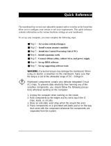
2: Mainboard Installation
7
Chapter 2
Mainboard Installation
To install this mainboard in a system, please follow these
instructions in this chapter:
!
Identify the mainboard components
!
Install a CPU
!
Install one or more system memory modules
!
Make sure all jumpers and switches are set correctly
!
Install this mainboard in a system chassis (case)
!
Connect any extension brackets or cables to connecting
headers on the mainboard
!
Install other devices and make the appropriate connections to
the mainboard connecting headers.
Note:
1. Before installing this mainboard, make sure the jumper BAT1
is set to Normal setting. See this chapter for information about
locating jumper BAT1 and the setting options.
2. Never connect power to the system while installing; otherwise,
it may damage the mainboard.

Mainboard User’s Manual
8
Mainboard Components
This diagram helps you identify major components on this
mainboard.
Note: Any jumpers on your mainboard but not appearing in
this illustration are for testing only.

2: Mainboard Installation
9
I/O Ports
This illustration shown below is a side view of the built-in I/O
ports on this mainboard.
PS/2 Mouse
PS/2 Keyboard
Parallel Port
Game/MIDI Port
Serial Port COM1/3
USB Ports
Microphone Jack
Line-Out Jack
VGA Port
Line-In Jack
Install A CPU
This mainboard has a Socket 370 supporting FCPGA Celeron,
FCPGA Pentium III and Tualatin/Tualatin Celeron processors.
Do not support PPGA Celeron processor.
To ensure reliability, ensure that your processor has a
heatsink/cooling fan assembly.
Do not try to install a Socket 7 processor in the Socket-370. A
Socket 7 processor such as the Pentium-MMX, or the AMD K5/K6
does not fit in the Socket 370. Do not try to install PPGA
Celeron processor in Socket-370.
The following list notes the processors that are currently supported
by this mainboard.
FCPGA Celeron: 300~966 MHz, FSB: 66 MHz
FCPGA Pentium III: 500~1130MHz, FSB: 100MHz, 133MHz
Tualatin/Tualatin Celeron : up to 1.2GHz, FSB: 100MHz

Mainboard User’s Manual
10
Installing a Socket-370 Processor
Install a processor into the ZIF (Zero Insertion Force) Socket-370
on the mainboard.
1. Locate the Socket-370 and JFAN1. Pull the locking lever out
slightly from the socket and raise it to the upright position.

2: Mainboard Installation
DIMM2
DIMM1
Install Memory
This mainboard has two DIMM sockets for system memory
modules. You must install at least one memory module in order to
work out this mainboard.
For this mainboard, you must use 168-pin, 3.3V unbuffered PC100
or PC133 SDRAM memory modules. You can install any size
memory module from 32 MB to 512 MB, so the maximum
memory size is 2 x 512 MB = 1 GB.
Edge connectors on the memory modules have cut outs coinciding
with spacers in the DIMM sockets that memory modules can only
be installed in the correct orientation.
To install a module, push the retaining latches at either end of the
socket outwards. Position the memory module correctly and insert
it into the DIMM socket. Press the module down into the socket so
that the retaining latches rotate up and secure the module in place
by fitting into notches on the edge of the module.

Mainboard User’s Manual
2
Setting Jumper Switches
Jumpers are sets of pins connected together with caps. Jumper caps
change the way of mainboard’s operation by changing the
electronic circuits on the mainboard. If a jumper cap connects two
pins, we say those pins are SHORT; if the cap is removed, they are
OPEN.
Jumper JBAT1: Clear CMOS Memory
This jumper is to clear the contents of CMOS memory. You may
need to clear the CMOS memory if the settings in the Setup Utility
are incorrect that prevents your mainboard from operating. To clear
the CMOS memory, disconnect all the power cables from the
mainboard and then move the jumper cap into the CLEAR setting
for a few seconds.
Function Jumper Setting
Normal Operation Short Pins 1-2
Clear CMOS Memory Short Pins 2-3
Jumper J2: Codec Selector
This jumper is to select the onboard audio codec or Audio Modem
Riser (AMR) slot.
Function Jumper Setting
Primary codec onboard Short Pins 1-2
Primary Codec on AMR slot Short Pins 2-3
1
JBAT1
1
1
J2
JP5
A B C D
JMIC1
1
JP3A
1
JP3B
JP97JP95
1 1
JP96

2: Mainboard Installation
3
Jumper JP3: CPU Frequency Selectors
This jumper consists of two sets of 3-pin jumpers JP3-A and JP3-B.
This jumper is to select the frequency of the installed CPU.
Frequency 66 MHz 100 MHz 105 MHz 133 MHz
JP3-A
2-3 2-3 1-2 1-2
JP3-B
2-3 1-2 2-3 1-2
Jumper JP5: CPU Multiplier Selectors
This jumper consists of four sets of 2-pin jumpers JP5-D, JP5-C,
JP5-B and JP5-A. This jumper is to select the multiplier of the
installed CPU.
CPU Multiplier Selector: JP5
Multiplier 2.0 2.5 3.0 3.5 4.0 4.5 5.0
JP5-D
short short short short short Short short
JP5-C
short open short open short Open short
JP5-B
short short open open short Short open
JP5-A
short short short short open Open open
CPU Multiplier Selector: JP5
Multiplier 5.5 6.0 6.5 7.0 7.5 8.0 8.5+
JP5-D
short open open open open Open open
JP5-C
open short open short open Short open
JP5-B
open short short open open Short open
JP5-A
open short short short short Open open
Note: The CPU speed is equal to the CPU Frequency x the
CPU Multiplier.
Jumper JP95: BIOS Protect
This jumper is to make the BIOS read-only.
Function Jumper Setting
Enable(read-only) Short Pins 1-2
Disable Short Pins 2-3

Mainboard User’s Manual
4
Jumper JP96: Keyboard Power On
This jumper enables any keyboard activity to power up a system
previously in a standby or sleep state.
Function Jumper Setting
+5V Short Pins 1-2
+5V SB Short Pins 2-3
Jumper JP97: Flash ROM Voltage
This jumper enables to select voltage of flash ROM.
Function Jumper Setting
+5V Short Pins 1-2
+3.3V Short Pins 2-3
Jumper JMIC1: Microphone-Out Selector
This jumper selects the Microphone-Out to the back-oriented
Microphone jack or the front-oriented Microphone header.
Function Jumper Setting
Back-oriented MIC jack Short Pins 1-2
Front-oriented MIC header Open Pins 1-2

2: Mainboard Installation
5
Install the Mainboard
Install the mainboard in a system chassis (case). The board is an
ATX size mainboard with a twin-tier of I/O ports. Make sure your
case has an I/O cover plate that matches the ports on this
mainboard.
Install the mainboard in a case. Follow these instructions of the
case manufacturer to use the hardware and internal mounting
points on the chassis.
Connect the power connector from the power supply to the ATX
connector on the mainboard.
If there is a cooling fan installed in the system chassis, connect the
cable from the cooling fan to the JFAN2 fan power connector on
the mainboard.
Connect case switches and indicator LEDs respectively to the
PANEL switch and LED connector header.
JFAN2
ATX
PANEL
1

Mainboard User’s Manual
6
Power LED(-) Yellow
13
14
2
1
Power LED(-) Green
Power LED(+)
Power Button Pins 9-11
This illustration below gives you a guide of the header’s pin
assignment.
System State Dual Color POWER LED State
S0 Steady Green
S1 Green Blinking
S3 Steady Yellow
S4/S5 Off
HDD LED(+)
HDD LED(-)
Speaker Pins
4-6-8-10
Reset Switch
Pins 12-14
/