
TereScope700 and TereScope800
Wireless Optical Communication Links
Models TS700/100, TS700/155, TS700/G, TS800/155
User Manual

WIRELESS OPTICAL COMMUNICATIONS
User Manual
Document Number ML48237 (4703700), Rev. 4.0
February 2006
MRV Communications, Inc.
Web site: www. mrv.com

MRV Communications, Inc. – Installation Manual
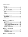
Table of Contents
STANDARDS
Standards Compliance ............................................................................i
FCC Notice ...............................................................................................i
CE Mark ...................................................................................................i
Other Standards .....................................................................................ii
MRV
TM
Laser Safety Certification........................................................ii
ABOUT THIS USER MANUAL
Audience .................................................................................................iii
Qualifications .........................................................................................iii
Training ..................................................................................................iii
Experience ..............................................................................................iii
Authorization .........................................................................................iii
SAFETY REQUIREMENTS
Before Installing ....................................................................................iv
Before Powering On ..............................................................................iv
When Installing ......................................................................................iv
Servicing ..................................................................................................v
INTRODUCTION ...............................................................................vi
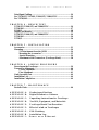
CHAPTER 1 - THE PRODUCT
Models.......................................................................................................1
General Description ................................................................................2
Front.........................................................................................................2
Back ..........................................................................................................3
A. TS700/155 (Standard Model)............................................................3
B. TS800/155 (Standard Model)............................................................5
C. TS800/155-F (Standard Model including Fusion option)..............8
D. TS700/100 (Fast Ethernet)..............................................................11
E. TS700/G (Gigabit Ethernet)............................................................13
Monitoring & Management Options...................................................15
Typical Connection................................................................................16
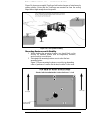
CHAPTER 2 - SITE SURVEY
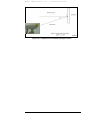
Line of Sight...........................................................................................17
Orientation.............................................................................................17
Location & Range..................................................................................17
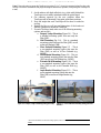
Mounting Environment & Stability.....................................................20
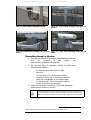
Transmitting through a Window.........................................................22
CHAPTER 3 - INFRASTRUCTURE
Power......................................................................................................24

MRV Communications, Inc. – Installation Manual
Data/Signal Cabling ..............................................................................24
For TS700/155, TS700/G, TS800/155, TS800/155-F............................24
For TS700/100.........................................................................................25
CHAPTER 4 - BENCH TEST
TS700/155, TS800/155, and TS800/155-F............................................26
TS700/100...............................................................................................27
TS100/G..................................................................................................28
Display and Results...............................................................................29
TS700/155, TS800/155, and TS800/155-F............................................29
TS700/100...............................................................................................30
TS700/G..................................................................................................30
CHAPTER 5 - INSTALLATION
Accessories .............................................................................................31
Mounting................................................................................................34
TS Detachement from the JMP-L ..............................................34
Mounting the Accessories............................................................35
Special Mounting.........................................................................36
Attachment of the Transceiver (TereScope Head) ...................38
CHAPTER 6 - AIMING PROCEDURE
Powering on the TereScope..................................................................39
Transceiver Alignment..........................................................................40
Coarse Alignment.........................................................................40
Fine Alignment.............................................................................41
Link Operating Test..............................................................................44
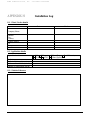
Installation Log......................................................................................44
Installation Completion ........................................................................44
CHAPTER 7 - MAINTENANCE
Periodic Visits........................................................................................40
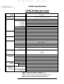
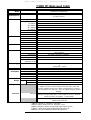
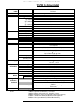
APPENDIX A: Product specifications
APPENDIX B: Digital Readout vs. Distance
APPENDIX C: Unpacking Instructions for TereScope
APPENDIX D: Tool Kit, Equipment, and Materials
APPENDIX E: TereScope Bench Test Procedure
APPE NDIX F: Effect of wind on TereScopes
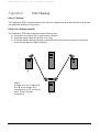
APPENDIX G: FSO Chaining
APPENDIX H: Installation Log
APPENDIX I: Power over Ethernet

MRV Communications, Inc. – Installation Manual
i
Standards
Standards Compliance
UL 1950; CSA 22.2 No 950; FCC Part 15 Class B; CE-89/336/EEC, 73/23/EEC
FCC Notice
WARNING: This equipment has been tested and found to comply with the limits for a Class B digital
device, pursuant to Part 15 of the FCC Rules. These limits are designed to provide reasonable protection
against harmful interference when the equipment is operated in a commercial environment. This
equipment generates, uses, and can radiate radio frequency energy and, if not installed and used in
accordance with the instructions in the manual, may cause harmful interference to radio
communications. Operation of this equipment in a residential area is likely to cause harmful interference
in which case the user will be required to correct for the interference at the user’s own expense.
The user is cautioned that changes and modifications made to the equipment without approval of the
manufacturer could void the user’s authority to operate this equipment.
It is suggested that the user use only shielded and grounded cables when appropriate to ensure
compliance with FCC Rules.
CE Mark
The CE mark symbolizes compliance with the EMC directive of the European Community. Such
marking is indicative that the specified equipment meets or exceeds the following technical standards:
•
EN 55022 - Limits and Methods of Measurement of Radio Interference Characteristics of
Information Technology Equipment
•
EN 50081-1- Electromagnetic compatibility - of Radio Interference Characteristics of
Information Technology Equipment Generic Emission standard Part 1 – Residential
commercial and light industry environment
•
EN 50082-1 - Electromagnetic compatibility -- Generic immunity standard Part 1:
Residential, commercial and light industry environment
•
EN61000-4-2 (previously IEC 1000-4-2) - Electromagnetic compatibility for industrial-
process measurement and control equipment Part 4: Section 2 - Electrostatic discharge
requirements
•
EN61000-4-3 (previously IEC 1000-4-3) - Electromagnetic compatibility for industrial-
process measurement and control equipment Part 4: Section 3 - Radiated electromagnetic
field requirements
•
EN61000-4-4 (previously IEC 1000-4-4) - Electromagnetic compatibility for industrial-
process measurement and control equipment Part 4: Section 4 - Electrical fast
transient/burst requirements
•
EN61000-4-5 - Electromagnetic compatibility for industrial-process measurement and
control equipment
Part 4: Section 5 – Surge Immunity requirements
•
EN61000-4-6 - Electromagnetic compatibility for industrial-process measurement and
control equipment
Part 4: Section 6 – Immunity to conducted disturbances induces by radio frequency fields
•
EN61000-4-8- Electromagnetic compatibility for industrial-process measurement and
control equipment
Part 4: Section 8– Power frequency magnetic field immunity requirements
•
EN61000-4-11 – Electromagnetic compatibility for industrial-process measurement and
control equipment Part 4: Section 11 – Voltage dips short interruptions and voltage
variations immunity requirements
•
EN61000-3-2 – Harmonic standard
•
EN61000-3-3 – Voltage Fluctuation and Flicker standard
•
CISPR 22 - Radiated and Line-conducted Class B
•
EN 60950 - ITE Safety

MRV Communications, Inc. – Installation Manual
ii
Other Standards
1. CISPR 22: 1993
AS/NZS 3548: 1995, Class B
Joint Amendment No. 1: 1997, Joint Amendment No. 2: 1997
2. EN 60950+A1+A2+A3+A4+A11
ACA TS001-1997
AS/NZS 3260: 1993 A4: 1997
3. ITU G.703, G.704, G.706,G.736, G.737, G.738, G739, G740, G.775, G.823.
MRV
Laser Safety Certification
The TereScope is designed, built, and tested to be eyesafe, even if the output beams are viewed directly,
provided that no magnifying optics are used.
This product is Class 1M according to the American National Standard for Safe Use of Lasers, ANSI
Z136.1-1993, provided that there is not a reasonable probability of accidental viewing with optics in the
direct path of the beam where the TereScope is installed.
This product is Class 1M according to the International Standard of the International Electrotechnical
Commision IEC 60825-1, Amendment 2, January 2001 entitled “Safety of laser products.” The following
explanatory label is applicable to these products:
LASER RADIATION
DO NOT VIEW DIRECTLY WITH OPTICAL INSTRUMENTS
(BINOCULARS OR TELESCOPES)
CLASS 1M LASER PRODUCT
This product complies with United States FDA performance standards for laser products except for
deviations pursuant to Laser Notice No. 50 as published in June, 2001, which allows for the use of the
IEC 60825-1 classification standard. Under this standard, these products are Class 1M.
A ‘Declaration of Conformity’, in accordance with the above standards, has been made and is on file at
MRV.
Disclaimer
MRV
reserves the right to modify the equipment at any time and in any way it sees fit in order to improve it.
MRV provides this document without any warranty of any kind, either expressed or implied, including, but not
limited to, the implied warranties of merchantability or fitness for a particular purpose.
The customer is advised to exercise due discretion in the use of the contents of this document since the customer
bears sole responsibility.
Trademarks
All trademarks are the property of their respective holders.
Copyright © 2004 by MRV
All rights reserved. No part of this document may be reproduced without the prior permission of MRV.
This document and the information contained herein are proprietary to MRV and are furnished to the
recipient solely for use in operating, maintaining and repairing MRV
equipment. The information within
may not be utilized for any purpose except as stated herein, and may not be disclosed to third parties
without written permission from MRV. MRV
reserves the right to make changes to any technical
specifications in order to improve reliability, function, or design.

MRV Communications, Inc. – Installation Manual
iii
About this User Manual
Audience
This manual is intended for the user who wishes to install, operate, manage and
troubleshoot the TereScope700 and TereScope800.
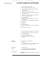
Qualifications
Users of this guide are expected to have:
• Working knowledge of Electro-optical equipment
• Working knowledge of LAN equipment (Layer 2 and 3)
• A License to install equipment on buildings/elevated structures
• A License to work with power line (mains) voltages 110/230 Vac
Training
Installers are required to do a training course on MRV TereScopes that includes:
• IR links (site survey, installation equipment, alignment, etc.)
• Indoors and outdoors installation
• On-the-job-training
• Proficiency tests
Experience
Installers are required to have experience in coax cable TV home pass installation,
PTT home pass installation, LAN installation, IR equipment installation, and home
electrical wiring.
Authorization
After all the requirements specified above (namely, Qualifications, Training, and
Experience) have been met, the installer must receive authorization from MRV
certifying eligibility.

MRV Communications, Inc. – Installation Manual
iv
Safety Requirements
All requirements stipulated in the safety laws of the country of installation must be
abided by when installing the TereScopes.
Caution!
In addition, ensure that the requirements noted in this chapter are met in
order to reduce risk of electrical shock and fire and to maintain proper
operation.
Before Installing
Power: Ensure that all power to the TereScope is cut off. Specifically,
disconnect all TereScope power cords from the power line (mains).
Inspection: Ensure by inspection that no part is damaged.
Before Powering On
Line Power: Ensure that the power from the line (mains) is as specified on
the TereScope.
Power Cord: The power cord of The TereScope must have the following
specifications:
Flexible 3-conductor power cord approved by the cognizant
safety organization of the country. The power cord must be
Type HAR (harmonized), with individual conductor wire
having cross-sectional area 0.75 sq. mm. min. The power cord
terminations should be a suitably rated earthing-type plug at
one end and 3 terminal cord forks for M3 screws (1 for each
wire) at the other end. Both of the power cord terminations
must carry the certification label of the cognizant safety
organization of the country.
When Installing
• Ensure, by visual inspection, that no part of the TereScope is damaged.
• Avoid eye contact with the laser beam at all times.
• Ensure that the system is installed in accordance with ANSI Z136.1
control measures (engineering, administrative, and procedural
controls).
• Ensure that the system is installed in accordance with applicable
building and installations codes.
• Install the TereScope in a restricted location as defined in this manual
since it is a Class 1M FSOCS transmitter and receiver. A restricted
location is a location where access to the transmission equipment and
exposed beam is restricted and not accessible to the general public or
Figure A: 3 terminal cord
forks

MRV Communications, Inc. – Installation Manual
v
casual passersby. Examples of restricted locations are: sides of
buildings at sufficient heights, restricted rooftops, and telephone poles.
This definition of a restricted location is in accordance with the
proposed IEC 60825-I Part 12 requirements.
• Avoid using controls, adjustments, or procedures other than those
specified herein as they may result in hazardous radiation exposure.
• Avoid prolonged eye contact with the laser beam (maximum 10 sec.).
Servicing
All servicing must be carried out only by qualified service personnel. Before
servicing, ensure that all power to the TereScope is cut off!

MRV Communications, Inc. – Installation Manual
vi
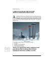
Introduction
CAREFULLY READ THE ENTIRE
MANUAL BEFORE INSTALLING
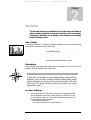
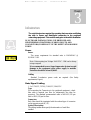
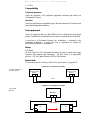
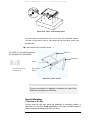
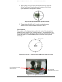
n InfraRed (IR) link allows connection without any cable between two
distant sites. For that, two identical transceivers, each installed on one site
and aligned to face each other, provide point-to-point connectivity. This
configuration makes possible data transfer from one terminal to the other
through the air over an optical wavelength carrier, the IR link – see picture in
Figure B, below.
Figure B: IR Link
The installation of such a link can be summarized as 4 stages:
♦
Site survey
♦
Installation of the infrastructure
♦
Mounting of the equipment
♦
Aiming (alignment) procedure
Always use appropriate safety equipment and
procedures when working with electrical
equipment and when working on roofs
.
A
!
!!
!

MRV Communications, Inc. – Installation Manual
1
The Product
Caution!
When handling the TereScope, take special care not to damage the
polycarbonate window!
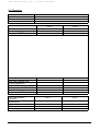
Models
Table 1: Models of the TereScope
1
Models
Part Number
Description
TS700/100 TS100/A/FET/VS TereScope700 for Fast Ethernet
100Base-TX connectivity up to a distance
of 360 m + Power-over-Ethernet option.
TS700/155 TS155/A/YUW/VS TereScope700 for 1-155 Mbps
connectivity up to a distance of 360 m.
TS700/G TS1000/A/YUW/VS TereScope700 for Gigabit Ethernet and
FiberChannel (1.0625) connectivity up to
a distance of 400 m
TS800/155 TS155/C2/YUW/VS TereScope800 for 1-155 Mbps
connectivity up to a distance of 550 m +
Fusion option.
Using the Part Number for Ordering
To place an order for a TereScope model having a specific configuration, use
the Part Number format shown in Table 1, noting the following:
‘155’ represents link operation speed in the range 1 to 155 Mbps.
‘A’ represents TereScope700.
‘C2’ represents TereScope800.
‘Y’ represents Optical Fiber Mode.
Instead of Y use one of the following:
M (for MultiMode)
1
TereScope700 or TereScope800.
Chapter
1

MRV Communications, Inc. – Installation Manual
2
S (for SingleMode)
‘U’ represents operating wavelength.
Instead of U use one of the following:
8 (for 850 nm)
3 (for 1310 nm)
5 (for 1550 nm)
‘W’ represents connector type.
Instead of W use one of the following:
C (for SC)
T (for ST)
‘FET’ (Fast ethernet) represents 100Base-TX with RJ45 connector
‘V’ represents existence/absence of Fusion.
Instead of V use one of the following:
V designates no built-in Fusion option.
F designates built-in Fusion option (only in TS800).
‘S’ represents power supply type.
Instead of S use one of the following:
S (for input to the power supply in the range 100-240 VAC)
3 (for input to the power supply in the range 24-60 VDC)
Examples
1 - TS155/A/M3C/VS means TS700/155 :1-155Mbps link, Multimode, 1310
nm, SC interface, 100-240 VAC power supply.
2 - TS155/C2/S3T/F3 : TS800/155 :1-155Mbps link, Singlemode, 1310 nm,
ST interface, built-in Fusion option, 24-60 VDC power supply.
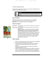
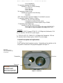
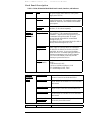
General Description and explanations
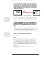
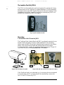
1. Front
Each TereScope head comprises a receiver, 1 transmitter and an interface on the
rear panel for connection to the peripheral equipment see Figure 1.1.
Figure 1.1: Front View
Front view
Showing the receiver
side, the transmitters and
the telescope
Telescope
Transmitter
Receiver
CAUTION!
AVOID EXPOSURE –
INVISIBLE LASER
RADIATION IS EMITTED
FROM THIS APERTURE

MRV Communications, Inc. – Installation Manual
3
HIGH
VOLT.
LOW
VOLT.
MRV
Switch
Ip
Address
Fast
Ethernet
Position
Data Rate
UP
Normal
DOWN
Local
Loopback
1 23
Mode of
Default IP
ATM
OC3
E3 T3
4,5
4
5
Normal
Alignment
-
4,5
-
4
5
TX RX
TELESCOPE
TORQUE VALUE 7 Lb-Inch
L G N
+/~ -/~
USE COPPER CONDUCTORS ONLY
POWER
OPTICAL POWER
SYNC
FLAG
FIBER OPTIC
NOT IN
USE
MANAGEMENT
1762310-SC
SYNC
FLAG
AIR RX
F/O RX
G
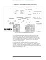
2. Back
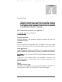
All models of the TereScope are SNMP manageable. SNMP monitoring can be
performed using MRV’s MegaVision SNMP management application.
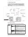
A. TS700/155 (Standard Model)
The TS700 supports Fast Ethernet, OC3, STM1, E3, and T3 protocols in the 34-
155 Mbps range. A special type of TS700 can be ordered that can be used for
Open Protocol applications which ensures complete transparency (including all
data in the range of 1-155 Mbps.) In this type, less than 2 dB of the budget is
lost.
Figure 1.2b: Rear View of TS700/155
Main Data:
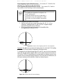
SC or ST
Connector
DIP Switch
Toggles 6,7,8
positions are
not used.
Figure 1.2a: TS700/155 Standard Model Panel Schematic
If you need to install the
SNMP card into the
TereScope, after installing
the card and before
closing the back panel,
carefully punch out this
piece of metal.

MRV Communications, Inc. – Installation Manual
4
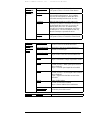
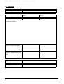
Back Panel Description
Table 2: TS700/155 Standard Model Back Panel Controls, Interfaces, and Indicators
Air RX Flag LED
Green LED indicates data received by the Airlink
receiver. Turns ON at the threshold level.
Air RX Sync LED Yellow LED. Turns ON if the rate of the received
Data matches the Data Rate set on the Data Rate
DIP switch.
F/O RX Flag LED Green LED indicates Data received by the Fiber
Optic receiver. Turns ON at the threshold level.
F/O RX Sync LED Yellow LED. Turns ON if the rate of the received
Data matches the Data Rate set on the Data Rate
DIP switch.
Indicators
(7-segment
display,
LEDs)
Optical Power 7-
segment display
Digital readout indicates the Optical Power level
received by the Airlink receiver.
Alignment Telescope
For fine alignment.
Connectors
Power
Power source Terminal Block (Main or UPS)
AC power supply (100 to 240 Vac) or DC power
supply (24 to 60 Vdc)
Fiber optic
Fiber Optic interface for connection to the
peripheral equipment. The standard interface is MM
1310nm SC connector; other interfaces are available
upon request.
Management
(Optional)
Connection to 10base-T SNMP management
interface. (To be ordered separately)
Mode of Operation
(Toggles 1 and 2)
Set the Operating Mode
ALIGNMENT = Idle transmitted automatically
NORMAL = Signal received through the F/O port
is transmitted through the Airlink TX. Signal
received through the Airlink RX is transmitted
through the F/O TX.
LOOPBACK=The Data received by the F/O RX is
directly returned through the F/O TX.
IP address set up
(for Mgt. option)
(Toggle 3)
Used only with the management option. When the
Switch toggle is on OFF position, the TereScope’s
IP address is the default one (shown on the back
panel label: 10.0.0.101). To set a new IP address
please refer to the “IP address setting procedure for
TereScope management card” file in the Manuals
CD. The new IP address is valid only after the
TereScope is powered off and on.
Selectors
(DIP Switch
Toggles)
--
shown in Figure
1.3
Data Rate
(
Toggles 4 and 5)
Set the transmission rate of the transceiver (internal
clock).
- Fast Ethernet: 4,5 OFF
- ATM/OC3/STM1:155 Mbps: 4,5 ON
- E3: 34.368 Mbps: 5 OFF, 4 ON
- T3: 44.736 Mbps: 4 OFF, 5 ON

MRV Communications, Inc. – Installation Manual
5
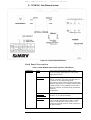
B. TS800/155 Standard Model
The TS800/155 supports most of the prevalent protocols in the 34-155 Mbps
range. Support for a special protocol, which is not on the list, can be ordered after
coordination with the factory. This model can be used for Open Protocol
applications which ensures complete transparency (including all data in the
range of 1-155 Mbps.) In this case, a maximum 2 dB of the power budget is lost.
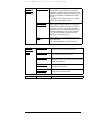
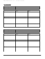
Back Panel Description
Table 3: TS800/155 Standard Model Back Panel Controls, Interfaces, and Indicators
Power
Power source Terminal Block (Main or UPS).
AC power supply (100 to 240 Vac) or DC power
supply (24 to 60 Vdc)
Fiber optic
Fiber Optic interface for connection to the
peripheral equipment. The standard interface is MM
1310nm SC connector; other interfaces are available
upon request.
In model TS800/155-F with the fusion option, there
are two fiberoptic interface ports for connection to
the Fusion system; one primary and the other
redundant.
Remote monitor Connection to the RSM. (The RSM has to be
ordered separately)
Connectors
Management
Connection to 10Base-T SNMP management
interface.
Pins 1,2: TX and 3,6 RX.
Pins (4,5) and (7,8) of this connector can be used
for dry contact purposes, for Airlink flag and F/O
fla
g
alarms res
p
ectivel
y
Figure 1.3: TS800/155 Standard Model Panel Schematic

MRV Communications, Inc. – Installation Manual
6
Note:
Pins (4,5) and (7,8) of the management RJ45 connector can be used for dry
contact purposes, for Airlink flag and F/O flag alarms respectively.
Selectors
(DIP Switch
DS1 Toggles)
-- shown in
Figure 1.3and
1.4
Data Rate
(Toggles 1,2,3,4)
Set the transmission rate of the transceiver (internal
clock).
- Fast Ethernet: 1,2,3,4 OFF
- ATM/OC3/STM1:155 Mbps: 2,3,4 OFF, 1 ON
- SMPTE 143 Mbps: 3,4 OFF, 1,2 ON
- E3: 34.368 Mbps1,2,4 OFF, 3 ON
- T3: 44.736 Mbps: 2,4 OFF, 1,3 ON
- OC1/STM0: 51.840 Mbps: 1,4 OFF, 2,3 ON
- Customized 1 : 4 OFF, 1,2,3 ON
- Customized 2 : 1,3,4 OFF, 2 ON
- Open Protocol: 1,2,3 OFF, 4 ON.
Mode Select
(Toggles 1, 2, 3)
Set the Operating Mode
ALIGNMENT = Idle transmitted automatically
NORMAL = Signal received via the F/O port is
transmitted through the Airlink TX. Signal received
via the Airlink RX is transmitted through the F/O
TX.
LOOPBACK= Data received by the F/O RX is
directly returned through the F/O TX.
REMOTE LOOP = Loops the electrical RX to the
electrical TX and optical RX to the optical TX of the
remote unit.
ATTENUATION: The alignment signal is
attenuated (~20db) when the DIP switch toggle #3
is moved to ON position.(to use when the
installation distance is less than 200m only for
alignment mode). Switch back to OFF position for
normal mode.
Laser Power Off
(Toggle 4)
Turning off laser TX when the DIP switch toggle is
moved to ON
Fusion
(Toggle 5)
This switch toggle enables working with MRV’s
Fusion system (Built-in fusion option or switch
option). For additional information, see page 7.
Switch toggle 5 OFF: Fusion not Active (Disabled)
Switch toggle 5 ON: Fusion active (Enabled).
Window Heater
(Optional)
(Toggle 6)
Used only with the heating option (To be specified
in the PO).
Switch toggle 6 OFF: The heater is disabled
Switch toggle 5 ON: The heater is enabled.
IP address set up
(Toggle 7)
When the Switch toggle is on OFF position, the
TereScope’s IP address is the default one (shown on
the back panel label: 10.0.0.101). To set a new IP
address please refer to the “IP address setting
procedure for TereScope management card” file in
the Manuals CD. The new IP address is valid only
after the TereScope is powered off and on.
Selectors
(DIP Switch
DS2 Toggles)
-- shown in
Figure 1.3
and
1.4
Control Mode
(Toggle 8)
When the Dip Switch toggle #8 is on OFF position,
the TereScope is in the HARDWARE mode, i.e. the
TereScope is controlled only by the TereScope itself
by means of the switches on its back panel.
When the Dip Switch toggle is on ON position, the
TereScope is in the SOFTWARE mode i.e. the
TereScope is controlled by the management
Software and various functions can be activated by
means of this management Software.

MRV Communications, Inc. – Installation Manual
7
Air RX Flag LED
Green LED indicates data received by the Airlink
receiver. Turns ON at the threshold level.
Air RX Sync LED Yellow LED. Turns ON if the rate of the received
Data matches the Data Rate set on the Data Rate
DIP switch.
F/O Main, RX Flag
LED
Upper green LED indicates Data received by the
Fiber Optic receiver. Turns ON at the threshold
level.
F/O Main, RX Sync
LED
Lower green LED. Turns ON if the rate of the
received Data matches the Data Rate set on the
Data Rate
DIP switch.
F/O Redundant, RX
Flag LED
(Optional)
Upper green LED indicates Data received by the
Fiber Optic receiver. Turns ON at the threshold
level.
F/O Redundant, RX
Sync LED
(Optional)
Lower green LED. Turns ON if the Fusion is
active and there is synchronisation with the
received Data
.
Optical Power 7-
segment display
Digital readout indicates the Optical Power level
received by the Airlink receiver.
Alignment LED Yellow LED. Turns ON if the Alignment
Operating Mode is selected.
Loopback LED Yellow LED. Turns ON in LOOPBACK mode.
Flashing in Remote Loop mode.
Fusion LED Yellow LED. Turns ON if the Fusion mode is
enabled.
Flashing when the Fusion (radio back-up system) is
active.
SW Mode LED Red LED. Turns ON if the SW Mode
(SOFTWARE) Operating Mode is selected.
Laser Status Shining Red LED: Turns ON when the Laser is
ON and turns OFF when the laser is powered off
by pushing the DS toggle #4 ON.
Management TX Flashing when the RSM-SNMP is connected and
the TereScope is transmitting management Data.
(There is no Link indication)
Indicators
(7-segment
display and
LEDs)
Management RX Flashing when the RSM-SNMP is connected and
the TereScope is receiving management Data.
(There is no Link indication)
Alignment Telescope
For fine alignment.

MRV Communications, Inc. – Installation Manual
8
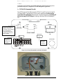
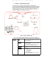
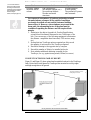
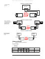
C. TS800/155-F (Standard Model including Fusion option)
This special TS800/155-F model can be connected to the back-up radio
system without a special MRV switch and card supporting Fusion. This
TereScope can be connected to any switch (supporting 10/100 Mbps data
rate) via a standard converter that should be connected to the optical port of
the TereScope labeled “Redundant”, while the back-up radio system is
connected to the same Switch.
As an alternative, the TereScope can be directly connected to a Media
Converter of type 10/100 TX-100 FX (for example, MRV’s media converter
MC102F). When the TereScope stops operating, the connectivity from the
main optical module to the air channel stops and starts flowing into the second
optical module designated for radio.
Figure 1.4: TS800/155-F Standard Model Panel Schematic

MRV Communications, Inc. – Installation Manual
9
That’s what
happens when
the air channel
is interrupted.
F/O
Network
RF
T
ransce
i
ver
10/100TX-100FX
Media Converter
Switch
10/100 Base-T
MC
10 Base-T
STP
F/O
Main
TS
TS
IR = 100 Mbps
Network
Main
RF
T
ransce
i
ver
RF = 2-10 Mbps
F/O
F/O
10 Base-T
STP
Redundant
Redundant
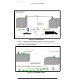
Figure 1.5a: TereScope800/155 F - & Fusion System Connection
For a description of the Back Panel and all the functions, see Paragraph B table 3, and
Paragraph C Figure 1.4 – TS800 with Fusion model, page 8.
Fusion Operation Mode
When at least one of the air channels (IR) is cut for more than one second or drops to
approximately 60 mV at the display readout:
1. TereScope switches to Fusion mode
2. Data is transmitted from Main module to Redundant module without passing
through the air channel
3. The signal is converted to 10Base-T by the Switch and the data Rate decreases
to 2-10 Mbps
The system switches back to IR channel (TereScope) only when the display readout on both
sides increases to approximately 150 mV.
Note: To activate the Fusion option, set DIP Switch toggle 5 to the ON position.

MRV Communications, Inc. – Installation Manual
10
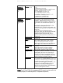
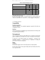
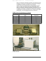
Fusion
Maximizing Link Availability in All Weather Conditions.
The TereScope Fusion was designed to combine the best features of two
transport mediums, laser light and radio waves, to form a single, seamless,
wireless communication link between network devices. By leveraging both
technologies, we can provide the 99.999% availability that your network
requires.
The TereScope Fusion has been specifically constructed to maximize link
availability between network nodes. These systems use the internationally
unlicensed, 2.4 GHz ISM band and are used as a backup for a number of
TereScope systems.
TereScope Fusion systems have an optical wireless link that provides Fast
Ethernet connectivity as the primary link and Ethernet RF as the backup link.
These systems operate in most weather conditions, including heavy rain, snow,
and fog with nearly 100% link availability. Ease of installation and freedom
from licensing make these systems very simple to deploy.
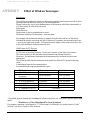
Protocol: 10Base-T (IEEE 802.1 1 b)
Frequency: 2.4 - 2.4835 GHz
ISM band (ETSI, FCC
2.4 – 2.497 GHz (Japan)
Output Power: -4 to 24 dBm
Sensitivity: -85 dBm
Operating Power: 110/220 VAC, 500/250 mA
Interface: Shielded RJ45
Specifications are subject to change at any time
without notice.
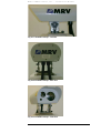
Figure 1.5b: TS & Fusion
Page is loading ...
Page is loading ...
Page is loading ...
Page is loading ...
Page is loading ...
Page is loading ...
Page is loading ...
Page is loading ...
Page is loading ...
Page is loading ...
Page is loading ...
Page is loading ...
Page is loading ...
Page is loading ...
Page is loading ...
Page is loading ...
Page is loading ...
Page is loading ...
Page is loading ...
Page is loading ...
Page is loading ...
Page is loading ...
Page is loading ...
Page is loading ...
Page is loading ...
Page is loading ...
Page is loading ...
Page is loading ...
Page is loading ...
Page is loading ...
Page is loading ...
Page is loading ...
Page is loading ...
Page is loading ...
Page is loading ...
Page is loading ...
Page is loading ...
Page is loading ...
Page is loading ...
Page is loading ...
Page is loading ...
Page is loading ...
Page is loading ...
Page is loading ...
Page is loading ...
Page is loading ...
Page is loading ...
Page is loading ...
Page is loading ...
Page is loading ...
Page is loading ...
Page is loading ...
Page is loading ...
Page is loading ...
Page is loading ...
Page is loading ...
Page is loading ...
-
 1
1
-
 2
2
-
 3
3
-
 4
4
-
 5
5
-
 6
6
-
 7
7
-
 8
8
-
 9
9
-
 10
10
-
 11
11
-
 12
12
-
 13
13
-
 14
14
-
 15
15
-
 16
16
-
 17
17
-
 18
18
-
 19
19
-
 20
20
-
 21
21
-
 22
22
-
 23
23
-
 24
24
-
 25
25
-
 26
26
-
 27
27
-
 28
28
-
 29
29
-
 30
30
-
 31
31
-
 32
32
-
 33
33
-
 34
34
-
 35
35
-
 36
36
-
 37
37
-
 38
38
-
 39
39
-
 40
40
-
 41
41
-
 42
42
-
 43
43
-
 44
44
-
 45
45
-
 46
46
-
 47
47
-
 48
48
-
 49
49
-
 50
50
-
 51
51
-
 52
52
-
 53
53
-
 54
54
-
 55
55
-
 56
56
-
 57
57
-
 58
58
-
 59
59
-
 60
60
-
 61
61
-
 62
62
-
 63
63
-
 64
64
-
 65
65
-
 66
66
-
 67
67
-
 68
68
-
 69
69
-
 70
70
-
 71
71
-
 72
72
-
 73
73
-
 74
74
-
 75
75
-
 76
76
-
 77
77


MRV Communications TS700/100 User manual
- Category
- Networking
- Type
- User manual
Ask a question and I''ll find the answer in the document
Finding information in a document is now easier with AI
Related papers
-
MRV Communications Mouse TS5000/4U1/V*) User manual
-
 MRV Communications EM316-2SFP User manual
-
 MRV Communications EM316SW-XY User manual
-
 MRV Communications EM316EDFA-LPR User manual
-
 MRV Communications EM316E1 User manual
-
 MRV Communications LX-4000 Series User manual
-
 MRV Communications EM316E3SF User manual


Other documents
-
Chauvet RGX User manual
-
 Mason Aluminum Framed Wall Mount Swing Up Rest Benches Installation guide
-
 CTC Store FSW2104 User manual
-
Rasonic RSM-B68W User manual
-
 D'Vontz HBV3-AB Installation guide
-
AirLink UG-ASW116-1103 User manual
-
-
Powermatic Mobile Base Extension Kit Owner's manual
-
-
RKI Instruments AirLink Alert Owner's manual


