Page is loading ...

NI Vision
NI 17xx Smart Camera User Manual
NI 17xx Smart Camera User Manual
June 2008
372429B-01

Support
Worldwide Technical Support and Product Information
ni.com
National Instruments Corporate Headquarters
11500 North Mopac Expressway Austin, Texas 78759-3504 USA Tel: 512 683 0100
Worldwide Offices
Australia 1800 300 800, Austria 43 662 457990-0, Belgium 32 (0) 2 757 0020, Brazil 55 11 3262 3599,
Canada 800 433 3488, China 86 21 5050 9800, Czech Republic 420 224 235 774, Denmark 45 45 76 26 00,
Finland 358 (0) 9 725 72511, France 01 57 66 24 24, Germany 49 89 7413130, India 91 80 41190000,
Israel 972 3 6393737, Italy 39 02 41309277, Japan 0120-527196, Korea 82 02 3451 3400,
Lebanon 961 (0) 1 33 28 28, Malaysia 1800 887710, Mexico 01 800 010 0793, Netherlands 31 (0) 348 433 466,
New Zealand 0800 553 322, Norway 47 (0) 66 90 76 60, Poland 48 22 3390150, Portugal 351 210 311 210,
Russia 7 495 783 6851, Singapore 1800 226 5886, Slovenia 386 3 425 42 00, South Africa 27 0 11 805 8197,
Spain 34 91 640 0085, Sweden 46 (0) 8 587 895 00, Switzerland 41 56 2005151, Taiwan 886 02 2377 2222,
Thailand 662 278 6777, Turkey 90 212 279 3031, United Kingdom 44 (0) 1635 523545
For further support information, refer to the Technical Support and Professional Services appendix. To comment
on National Instruments documentation, refer to the National Instruments Web site at
ni.com/info and enter
the info code
feedback.
© 2007–2008 National Instruments Corporation. All rights reserved.

Important Information
Warranty
NI 17xx Smart Cameras are warranted against defects in materials and workmanship for a period of one year from the date of shipment, as
evidenced by receipts or other documentation. National Instruments will, at its option, repair or replace equipment that proves to be defective
during the warranty period. This warranty includes parts and labor.
The media on which you receive National Instruments software are warranted not to fail to execute programming instructions, due to defects in
materials and workmanship, for a period of 90 days from date of shipment, as evidenced by receipts or other documentation. National Instruments
will, at its option, repair or replace software media that do not execute programming instructions if National Instruments receives notice of such defects
during the warranty period. National Instruments does not warrant that the operation of the software shall be uninterrupted or error free.
A Return Material Authorization (RMA) number must be obtained from the factory and clearly marked on the outside of the package before any
equipment will be accepted for warranty work. National Instruments will pay the shipping costs of returning to the owner parts which are covered by
warranty.
National Instruments believes that the information in this document is accurate. The document has been carefully reviewed for technical accuracy. In
the event that technical or typographical errors exist, National Instruments reserves the right to make changes to subsequent editions of this document
without prior notice to holders of this edition. The reader should consult National Instruments if errors are suspected. In no event shall National
Instruments be liable for any damages arising out of or related to this document or the information contained in it.
E
XCEPT AS SPECIFIED HEREIN, NATIONAL INSTRUMENTS MAKES NO WARRANTIES, EXPRESS OR IMPLIED, AND SPECIFICALLY DISCLAIMS ANY WARRANTY OF
MERCHANTABILITY OR FITNESS FOR A PARTICULAR PURPOSE. CUSTOMER’S RIGHT TO RECOVER DAMAGES CAUSED BY FAULT OR NEGLIGENCE ON THE PART OF NATIONAL
I
NSTRUMENTS SHALL BE LIMITED TO THE AMOUNT THERETOFORE PAID BY THE CUSTOMER. NATIONAL INSTRUMENTS WILL NOT BE LIABLE FOR DAMAGES RESULTING
FROM LOSS OF DATA, PROFITS, USE OF PRODUCTS, OR INCIDENTAL OR CONSEQUENTIAL DAMAGES, EVEN IF ADVISED OF THE POSSIBILITY THEREOF. This limitation of
the liability of National Instruments will apply regardless of the form of action, whether in contract or tort, including negligence. Any action against
National Instruments must be brought within one year after the cause of action accrues. National Instruments shall not be liable for any delay in
performance due to causes beyond its reasonable control. The warranty provided herein does not cover damages, defects, malfunctions, or service
failures caused by owner’s failure to follow the National Instruments installation, operation, or maintenance instructions; owner’s modification of the
product; owner’s abuse, misuse, or negligent acts; and power failure or surges, fire, flood, accident, actions of third parties, or other events outside
reasonable control.
Copyright
Under the copyright laws, this publication may not be reproduced or transmitted in any form, electronic or mechanical, including photocopying,
recording, storing in an information retrieval system, or translating, in whole or in part, without the prior written consent of National
Instruments Corporation.
National Instruments respects the intellectual property of others, and we ask our users to do the same. NI software is protected by copyright and other
intellectual property laws. Where NI software may be used to reproduce software or other materials belonging to others, you may use NI software only
to reproduce materials that you may reproduce in accordance with the terms of any applicable license or other legal restriction.
Trademarks
National Instruments, NI, ni.com, and LabVIEW are trademarks of National Instruments Corporation. Refer to the Terms of Use section
on
ni.com/legal for more information about National Instruments trademarks.
Other product and company names mentioned herein are trademarks or trade names of their respective companies.
Members of the National Instruments Alliance Partner Program are business entities independent from National Instruments and have no agency,
partnership, or joint-venture relationship with National Instruments.
Patents
For patents covering National Instruments products, refer to the appropriate location: Help»Patents in your software, the patents.txt file
on your media, or ni.com/patents.
WARNING REGARDING USE OF NATIONAL INSTRUMENTS PRODUCTS
(1) NATIONAL INSTRUMENTS PRODUCTS ARE NOT DESIGNED WITH COMPONENTS AND TESTING FOR A LEVEL OF
RELIABILITY SUITABLE FOR USE IN OR IN CONNECTION WITH SURGICAL IMPLANTS OR AS CRITICAL COMPONENTS IN
ANY LIFE SUPPORT SYSTEMS WHOSE FAILURE TO PERFORM CAN REASONABLY BE EXPECTED TO CAUSE SIGNIFICANT
INJURY TO A HUMAN.
(2) IN ANY APPLICATION, INCLUDING THE ABOVE, RELIABILITY OF OPERATION OF THE SOFTWARE PRODUCTS CAN BE
IMPAIRED BY ADVERSE FACTORS, INCLUDING BUT NOT LIMITED TO FLUCTUATIONS IN ELECTRICAL POWER SUPPLY,
COMPUTER HARDWARE MALFUNCTIONS, COMPUTER OPERATING SYSTEM SOFTWARE FITNESS, FITNESS OF COMPILERS
AND DEVELOPMENT SOFTWARE USED TO DEVELOP AN APPLICATION, INSTALLATION ERRORS, SOFTWARE AND HARDWARE
COMPATIBILITY PROBLEMS, MALFUNCTIONS OR FAILURES OF ELECTRONIC MONITORING OR CONTROL DEVICES,
TRANSIENT FAILURES OF ELECTRONIC SYSTEMS (HARDWARE AND/OR SOFTWARE), UNANTICIPATED USES OR MISUSES, OR
ERRORS ON THE PART OF THE USER OR APPLICATIONS DESIGNER (ADVERSE FACTORS SUCH AS THESE ARE HEREAFTER
COLLECTIVELY TERMED “SYSTEM FAILURES”). ANY APPLICATION WHERE A SYSTEM FAILURE WOULD CREATE A RISK OF
HARM TO PROPERTY OR PERSONS (INCLUDING THE RISK OF BODILY INJURY AND DEATH) SHOULD NOT BE RELIANT SOLELY
UPON ONE FORM OF ELECTRONIC SYSTEM DUE TO THE RISK OF SYSTEM FAILURE. TO AVOID DAMAGE, INJURY, OR DEATH,
THE USER OR APPLICATION DESIGNER MUST TAKE REASONABLY PRUDENT STEPS TO PROTECT AGAINST SYSTEM FAILURES,
INCLUDING BUT NOT LIMITED TO BACK-UP OR SHUT DOWN MECHANISMS. BECAUSE EACH END-USER SYSTEM IS
CUSTOMIZED AND DIFFERS FROM NATIONAL INSTRUMENTS' TESTING PLATFORMS AND BECAUSE A USER OR APPLICATION
DESIGNER MAY USE NATIONAL INSTRUMENTS PRODUCTS IN COMBINATION WITH OTHER PRODUCTS IN A MANNER NOT
EVALUATED OR CONTEMPLATED BY NATIONAL INSTRUMENTS, THE USER OR APPLICATION DESIGNER IS ULTIMATELY
RESPONSIBLE FOR VERIFYING AND VALIDATING THE SUITABILITY OF NATIONAL INSTRUMENTS PRODUCTS WHENEVER
NATIONAL INSTRUMENTS PRODUCTS ARE INCORPORATED IN A SYSTEM OR APPLICATION, INCLUDING, WITHOUT
LIMITATION, THE APPROPRIATE DESIGN, PROCESS AND SAFETY LEVEL OF SUCH SYSTEM OR APPLICATION.

Compliance
Compliance with FCC/Canada Radio Frequency Interference
Regulations
Determining FCC Class
The Federal Communications Commission (FCC) has rules to protect wireless communications from interference. The FCC
places digital electronics into two classes. These classes are known as Class A (for use in industrial-commercial locations only)
or Class B (for use in residential or commercial locations). All National Instruments (NI) products are FCC Class A products.
Depending on where it is operated, this Class A product could be subject to restrictions in the FCC rules. (In Canada, the
Department of Communications (DOC), of Industry Canada, regulates wireless interference in much the same way.) Digital
electronics emit weak signals during normal operation that can affect radio, television, or other wireless products.
All Class A products display a simple warning statement of one paragraph in length regarding interference and undesired
operation. The FCC rules have restrictions regarding the locations where FCC Class A products can be operated.
Consult the FCC Web site at
www.fcc.gov for more information.
FCC/DOC Warnings
This equipment generates and uses radio frequency energy and, if not installed and used in strict accordance with the instructions
in this manual and the CE marking Declaration of Conformity*, may cause interference to radio and television reception.
Classification requirements are the same for the Federal Communications Commission (FCC) and the Canadian Department
of Communications (DOC).
Changes or modifications not expressly approved by NI could void the user’s authority to operate the equipment under the
FCC Rules.
Class A
Federal Communications Commission
This equipment has been tested and found to comply with the limits for a Class A digital device, pursuant to part 15 of the FCC
Rules. These limits are designed to provide reasonable protection against harmful interference when the equipment is operated
in a commercial environment. This equipment generates, uses, and can radiate radio frequency energy and, if not installed and
used in accordance with the instruction manual, may cause harmful interference to radio communications. Operation of this
equipment in a residential area is likely to cause harmful interference in which case the user is required to correct the interference
at their own expense.
Canadian Department of Communications
This Class A digital apparatus meets all requirements of the Canadian Interference-Causing Equipment Regulations.
Cet appareil numérique de la classe A respecte toutes les exigences du Règlement sur le matériel brouilleur du Canada.
Compliance with EU Directives
Users in the European Union (EU) should refer to the Declaration of Conformity (DoC) for information* pertaining to the
CE marking. Refer to the Declaration of Conformity (DoC) for this product for any additional regulatory compliance
information. To obtain the DoC for this product, visit
ni.com/certification, search by model number or product line,
and click the appropriate link in the Certification column.
* The CE marking Declaration of Conformity contains important supplementary information and instructions for the user or
installer.

© National Instruments Corporation v NI 17xx Smart Camera User Manual
Contents
About This Manual
Conventions ...................................................................................................................ix
Related Documentation..................................................................................................x
Hardware Documents ......................................................................................x
NI Vision Builder for Automated Inspection Documents...............................x
LabVIEW and NI Vision Development Module Documents..........................xi
NI Vision Acquisition Software Documents...................................................xi
Chapter 1
NI Smart Camera Overview
Hardware Overview.......................................................................................................1-1
Software Overview ........................................................................................................1-4
NI Vision Builder for Automated Inspection ..................................................1-4
LabVIEW ........................................................................................................1-5
LabVIEW Real-Time Module ..........................................................1-5
NI Vision Development Module.......................................................1-5
NI Vision Acquisition Software........................................................1-6
Chapter 2
Power and I/O
POWER-I/O Connector .................................................................................................2-1
NI Smart Camera Power Requirements.........................................................................2-2
Isolated Inputs................................................................................................................2-3
Isolated Outputs .............................................................................................................2-4
Protecting Against Inductive Loads ................................................................2-6
Connecting to Serial Devices.........................................................................................2-6
Communicating with the Console ...................................................................2-6
Connecting to a Quadrature Encoder.............................................................................2-7
Chapter 3
NI Smart Camera Image Sensor
Field of View .................................................................................................................3-1
Image Sensor Spectral Response ...................................................................................3-3
Partial Scan Mode..........................................................................................................3-3
Binning...........................................................................................................................3-4
Gain................................................................................................................................3-4
Hardware Binarization...................................................................................................3-5

Contents
NI 17xx Smart Camera User Manual vi ni.com
Chapter 4
Lighting
Lighting Connector........................................................................................................ 4-1
Direct Drive Lighting Controller................................................................................... 4-2
Lighting Files .................................................................................................. 4-4
Selecting a Light ............................................................................................. 4-5
Connecting a Light to the Direct Drive Lighting Controller .......................... 4-6
External Lighting Controllers........................................................................................ 4-7
Connecting an External Lighting Controller to the NI Smart Camera ........... 4-8
Chapter 5
Image Acquisition
Exposure ........................................................................................................................5-1
Acquiring Images .......................................................................................................... 5-2
Internal Timing ............................................................................................... 5-2
External Trigger .............................................................................................. 5-3
Maximum Frame Rate................................................................................................... 5-6
Determining the Maximum Frame Rate ......................................................... 5-7
Determining the Scan Mode ........................................................................... 5-7
Determining the Exposure Time ..................................................................... 5-8
Determining the Lighting Mode ..................................................................... 5-8
Determining the Trigger Delay ....................................................................... 5-9
Calculating the Minimum Frame Period......................................................... 5-9
Chapter 6
LEDs and DIP Switches
Understanding the LED Indicators................................................................................ 6-1
Device Initialization........................................................................................ 6-2
POWER LED.................................................................................................. 6-2
STATUS LED................................................................................................. 6-2
IMG ACQ LED............................................................................................... 6-4
PASS LED ...................................................................................................... 6-4
FAIL LED ....................................................................................................... 6-4
Configuring DIP Switches............................................................................................. 6-4
SAFE MODE Switch ...................................................................................... 6-5
IP RESET Switch............................................................................................ 6-5
NO APP Switch .............................................................................................. 6-6
CONSOLE Switch .......................................................................................... 6-6

Contents
© National Instruments Corporation vii NI 17xx Smart Camera User Manual
Chapter 7
Ethernet Ports
Ethernet LEDs................................................................................................................7-2
ACTIVITY/LINK LED...................................................................................7-2
SPEED LED ....................................................................................................7-2
DHCP and Static IP Address Assignment .....................................................................7-3
Firewall Considerations...................................................................................7-4
Subnet Considerations .....................................................................................7-4
Chapter 8
Thermal Considerations and Mounting
Thermal Considerations.................................................................................................8-1
Mounting the NI Smart Camera.....................................................................................8-2
Appendix A
Specifications
Appendix B
Troubleshooting
Appendix C
Maintenance
Appendix D
Technical Support and Professional Services
Glossary
Index

© National Instruments Corporation ix NI 17xx Smart Camera User Manual
About This Manual
This manual describes the electrical and mechanical aspects of the
National Instruments 17xx Smart Camera. Refer to Getting Started with
the NI 17xx Smart Camera for smart camera and accessory installation
information.
Conventions
The following conventions appear in this manual:
» The » symbol leads you through nested menu items and dialog box options
to a final action. The sequence File»Page Setup»Options directs you to
pull down the File menu, select the Page Setup item, and select Options
from the last dialog box.
This icon denotes a note, which alerts you to important information.
This icon denotes a caution, which advises you of precautions to take to
avoid injury, data loss, or a system crash. When this symbol is marked on
a product, refer to Getting Started with the NI 17xx Smart Camera for
information about precautions to take.
When symbol is marked on a product, it denotes a warning advising you to
take precautions to avoid electrical shock.
bold Bold text denotes items that you must select or click in the software, such
as menu items and dialog box options. Bold text also denotes parameter
names.
italic Italic text denotes variables, emphasis, a cross-reference, or an introduction
to a key concept. Italic text also denotes text that is a placeholder for a word
or value that you must supply.
monospace Text in this font denotes text or characters that you should enter from the
keyboard, sections of code, programming examples, and syntax examples.
This font is also used for the proper names of disk drives, paths, directories,
programs, subprograms, subroutines, device names, functions, operations,
variables, filenames, and extensions.
monospace italic
Italic text in this font denotes text that is a placeholder for a word or value
that you must supply.

About This Manual
NI 17xx Smart Camera User Manual x ni.com
Related Documentation
The following documents contain information that you may find helpful as
you read this manual:
Hardware Documents
• Getting Started with the NI 17xx Smart Camera—Contains important
safety information and information about installing and configuring
NI Smart Cameras and accessories. You can access this manual by
navigating to Start»All Programs»National Instruments»Vision»
Documentation»NI-IMAQ.
• NI Developer Zone—Contains example programs, tutorials, technical
presentations, the Instrument Driver Network, a measurement
glossary, an online magazine, a product advisor, and a community area
where you can share ideas, questions, and source code with developers
around the world. The NI Developer Zone is located on the National
Instruments Web site at
ni.com/zone. You can find the following
documents in the NI Developer Zone:
– Using the NI 17xx Smart Camera Direct Drive Lighting
Controller—Demonstrates how to utilize the Direct Drive lighting
controller feature on the NI 17xx Smart Camera with LabVIEW
or Vision Builder for Automated Inspection.
– A Practical Guide to Machine Vision Lighting—Explains
machine vision lighting concepts and theories.
NI Vision Builder for Automated Inspection Documents
• NI Vision Builder for Automated Inspection Tutorial—Describes
Vision Builder for Automated Inspection and provides step-by-step
instructions for solving common visual inspection tasks, such as
inspection, gauging, part presence, guidance, and counting.
• NI Vision Builder for Automated Inspection: Configuration
Help—Contains information about using the Vision Builder for
Automated Inspection Configuration Interface to create a machine
vision application.
• NI Vision Builder for Automated Inspection: Inspection
Help—Contains information about running applications created with
Vision Builder for Automated Inspection in the Vision Builder
Automated Inspection Interface.

About This Manual
© National Instruments Corporation xi NI 17xx Smart Camera User Manual
LabVIEW and NI Vision Development Module Documents
• LabVIEW Help—Includes information about LabVIEW programming
concepts, step-by-step instructions for using LabVIEW, and reference
information about LabVIEW VIs, functions, palettes, menus, and
tools.
• Getting Started with LabVIEW—Use this manual as a tutorial to
familiarize yourself with the LabVIEW graphical programming
environment and the basic LabVIEW features you use to build data
acquisition and instrument control applications.
• Getting Started with the LabVIEW Real-Time Module—Use this
manual as a tutorial to familiarize yourself with the LabVIEW
Real-Time Module and the basic Real-Time Module features you use
to build real-time applications.
• NI Vision Concepts Manual—Describes the basic concepts of image
analysis, image processing, and machine vision. This document also
contains in-depth discussions about imaging functions for advanced
users.
• NI Vision for LabVIEW Help—Describes how to create machine
vision and image processing applications in LabVIEW using the
Vision Development Module. The help file guides you through
tasks beginning with setting up your imaging system to taking
measurements. It also describes how to create a real-time vision
application using NI Vision with the LabVIEW Real-Time Module
and contains reference information about NI Vision for LabVIEW
palettes and VIs.
NI Vision Acquisition Software Documents
• NI-IMAQ VI Reference Help—Contains reference information about
the LabVIEW VIs and properties for NI-IMAQ driver software.
• Measurement & Automation Explorer Help for NI-IMAQ—Describes
how to configure NI-IMAQ driver software, NI image acquisition
devices, and NI Smart Cameras using Measurement & Automation
Explorer.

© National Instruments Corporation 1-1 NI 17xx Smart Camera User Manual
1
NI Smart Camera Overview
This chapter provides an overview of the features and components of the
National Instruments Smart Camera. Refer to Getting Started with the
NI 17xx Smart Camera for smart camera and accessory installation
information.
Hardware Overview
The NI Smart Camera is available in several different configurations.
When a feature pertains only to specific smart camera models, a list at the
beginning of the section shows which smart camera models support the
feature.
All smart camera models incorporate an image sensor, processor, and
digital I/O in a compact, rugged housing.
Table 1-1 shows the differentiating features for each smart camera model.
Table 1-1. NI Smart Camera Models
NI Smart
Camera
Model
Processor Image Sensor
Direct Drive
Lighting
Controller
Quadrature
Encoder
Support
NI 1722 400 MHz PowerPC 1/3 inch Sony ICX424AL CCD
Monochrome
640 × 480 pixels (VGA)
No No
NI 1742 533 MHz PowerPC 1/3 inch Sony ICX424AL CCD
Monochrome
640 × 480 pixels (VGA)
Yes Yes
NI 1744 533 MHz PowerPC 1/2 inch Sony ICX205AL CCD
Monochrome
1,280 × 1,024 pixels (SXGA)
Yes Yes
NI 1762 533 MHz PowerPC
and 720 MHz DSP
1/3 inch Sony ICX424AL CCD
Monochrome
640 × 480 pixels (VGA)
Yes Yes
NI 1764 533 MHz PowerPC
and 720 MHz DSP
1/2 inch Sony ICX205AL CCD
Monochrome
1,280 × 1,024 pixels (SXGA)
Yes Yes

Chapter 1 NI Smart Camera Overview
NI 17xx Smart Camera User Manual 1-2 ni.com
For more information about the image sensors, refer to Chapter 3, NI Smart
Camera Image Sensor. For complete smart camera specifications, refer to
Appendix A, Specifications.
All smart cameras have an RS-232 serial port, Gigabit Ethernet ports, and
use a standard C-mount lens. Some smart camera models also include the
Direct Drive lighting controller and support for quadrature encoders. The
Direct Drive lighting controller is an integrated controller to directly power
a variety of third-party current-controlled lights. Refer to Chapter 4,
Lighting, for more information about the Direct Drive lighting controller.
The smart camera also has one 5 V TTL strobe output and one unregulated
24 V strobe output for lighting control.
The smart camera also includes LEDs for communicating system status,
four DIP switches to specify startup options, isolated inputs, and isolated
outputs for connecting to external devices. Refer to Chapter 6, LEDs and
DIP Switches, for more information about the LEDs and DIP switches.
Refer to Chapter 2, Power and I/O, for more information about the digital
I/O capabilities of the smart camera.

Chapter 1 NI Smart Camera Overview
© National Instruments Corporation 1-3 NI 17xx Smart Camera User Manual
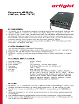
Figure 1-1 shows the smart camera.
Figure 1-1. NI Smart Camera
1 Image Sensor
2 Standard C Lens Mount
3 Lighting Connector
4LEDs
5 DIP Switches
6 POWER-I/O Connector
7 Ethernet Ports
GND
+
-
5V
24V
6
1
2
3
4
5
7
NI 17XX SMART CAMERA

Chapter 1 NI Smart Camera Overview
NI 17xx Smart Camera User Manual 1-4 ni.com
Software Overview
Developing applications with the NI Smart Camera requires one of the
following software options:
The installation and configuration process for each development
environment is different. Refer to Getting Started with the NI 17xx Smart
Camera for installation and configuration instructions.
The following sections describe the software options. For detailed
information about individual software packages, refer to the documentation
specific to the package.
Note Vision Builder for Automated Inspection and NI Vision Acquisition Software are
included with the smart camera. LabVIEW, the LabVIEW Real-Time Module, and the
NI Vision Development Module are sold separately.
NI Vision Builder for Automated Inspection
Vision Builder for Automated Inspection (Vision Builder AI) is
configurable machine vision software you can use to configure the
NI Smart Camera and prototype, benchmark, and deploy machine vision
applications.
Creating applications in Vision Builder AI does not require programming.
Vision Builder AI allows you to easily configure and benchmark a
sequence of visual inspection steps, as well as deploy the visual inspection
system for automated inspection. With Vision Builder AI, you can perform
powerful visual inspection tasks and make decisions based on the results
of individual tasks. You can also migrate your configured inspection to
LabVIEW, extending the capabilities of your applications if necessary.
Vision Builder
for
Automated Inspection
LabVIEW
LabVIEW Real-Time Module
NI Vision Development Module
NI Vision Acquisition Software
or

Chapter 1 NI Smart Camera Overview
© National Instruments Corporation 1-5 NI 17xx Smart Camera User Manual
LabVIEW
LabVIEW is a graphical programming environment for developing flexible
and scalable applications. To develop machine vision applications with the
NI Smart Camera and LabVIEW, you must have the following add-on
modules: LabVIEW Real-Time Module, NI Vision Development Module,
and Vision Acquisition Software.
LabVIEW Real-Time Module
The LabVIEW Real-Time Module combines LabVIEW graphical
programming with the power of Real-Time (RT) hardware, enabling you to
build deterministic, real-time systems. You develop VIs in LabVIEW and
embed the VIs on RT targets, such as the NI Smart Camera. The RT target
runs VIs without a user interface and offers a stable platform for real-time
VIs. For more information about the LabVIEW Real-Time Module, refer
to the LabVIEW Help.
NI Vision Development Module
The NI Vision Development Module is an image acquisition, processing,
and analysis library of hundreds of functions for the following common
machine vision tasks:
• Pattern matching
• Particle analysis
•Gauging
• Taking measurements
• Grayscale, color, and binary image display
With the NI Vision Development Module you can acquire, display, and
store images as well as perform image analysis and processing. Using the
NI Vision Development Module, imaging novices and experts can program
the most basic or complicated image applications without knowledge of
particular algorithm implementations.
For information about how to use the NI Vision Development Module with
the LabVIEW Real-Time Module, refer to the NI Vision for LabVIEW
Help.

Chapter 1 NI Smart Camera Overview
NI 17xx Smart Camera User Manual 1-6 ni.com
NI Vision Acquisition Software
The NI Vision Acquisition Software CD contains Measurement &
Automation Explorer (MAX) configuration software and NI-IMAQ driver
software.
Use MAX to configure the NI Smart Camera. You can set the IP address,
update software on the smart camera, configure triggering, and set up
the lighting features. For more information about MAX, refer to the
Measurement & Automation Explorer Help for NI-IMAQ
NI-IMAQ is the interface path between the application software and the
smart camera. NI-IMAQ also controls the I/O and image acquisition on the
smart camera.
NI-IMAQ includes an extensive library of VIs you can call from LabVIEW.
These VIs include routines for video configuration, continuous and
single-shot image acquisition, and trigger control.
The NI-IMAQ driver software performs all functions necessary for
acquiring and saving images but does not perform image analysis.
NI-IMAQ features both high-level and low-level functions. A function that
acquires images in single-shot or continuous mode is an example of a
high-level function. A function that requires advanced understanding of
image acquisition, such as configuring an image sequence, is an example
of a low-level function.
For information about using NI-IMAQ to configure an acquisition, refer to
the NI-IMAQ VI Reference Help.

© National Instruments Corporation 2-1 NI 17xx Smart Camera User Manual
2
Power and I/O
This chapter provides information about the NI Smart Camera
POWER-I/O connector, connecting isolated inputs and isolated outputs,
and connecting to serial devices and to quadrature encoders.
POWER-I/O Connector
The POWER-I/O connector provides signal connections for power and I/O,
including isolated inputs and outputs, quadrature encoders, and serial
devices. The POWER-I/O connector is a standard female high-density
15-pin D-SUB connector. Table 2-1 shows the pin organization for the
POWER-I/O connector. The two pins used to connect to a power supply,
pin 15 and pin 5, are also shown in the table. Refer to Getting Started with
the NI 17xx Smart Camera for information about connecting a power
supply to the NI Smart Camera.
Table 2-1 lists the signal names and pin numbers for the 15-pin
POWER-I/O connector. The table also lists the wire colors for the 15-pin
D-SUB pigtail cable (part number 197818-05), sold separately by National
Instruments. Cables sold by other manufacturers could have different wire
colors.
Table 2-1. POWER-I/O Connector Signal Descriptions
Connector Diagram Signal Name Pin Number Wire Color
+24 V 5 Red
COM 15 Black
RS232_TXD 10 Pink
RS232_RXD 14 Black/White
TrigIn+
IsoIn(0)+
2 Brown
IsoIn(1)+ 8 Orange
5 (+24 V)
15 (COM)
11
6
1
10

Chapter 2 Power and I/O
NI 17xx Smart Camera User Manual 2-2 ni.com
NI Smart Camera Power Requirements
Caution Use the NI Smart Camera only with a 24 VDC, UL listed, limited power source
(LPS) supply. The power supply should bear the UL listed mark, LPS. The power supply
must meet any safety and compliance requirements for the country of use.
The smart camera uses a nominal 24 VDC power source. The smart camera
accepts power within the range of the industry standard IEC 1311 input
power specification (24 V +20%/–15% with an additional allowance for an
AC peak of +5%). Refer to Appendix A, Specifications, for complete
power requirement specifications.
Caution The 24 V external lighting strobe is an unregulated output dependent on the range
of the power supply provided to the smart camera. If the power provided to the smart
camera is +20%/–15% with +5% AC ripple, the external lighting strobe output could be
as high as 30 V. If the provided power exceeds the input voltage specifications of the
third-party lighting controller, do not connect the 24 V lighting strobe output to the
controller to prevent damage to the controller. Use a power supply with tolerances that
meet the requirements of the controller, or use the 5 V external lighting strobe.
TrigIn–
IsoIn(0)–
IsoIn(1)–
12 Light Green
IsoOut(0)+ 6 Yellow
IsoOut(0)– 1 Green
IsoOut(1)+ 11 Light Blue
IsoOut(1)– 7 Gray
PhaseA+ 3 Blue
PhaseA– 13 Brown/White
PhaseB+ 9 Purple
PhaseB– 4 White
Table 2-1. POWER-I/O Connector Signal Descriptions (Continued)
Connector Diagram Signal Name Pin Number Wire Color
5 (+24 V)
15 (COM)
11
6
1
10

Chapter 2 Power and I/O
© National Instruments Corporation 2-3 NI 17xx Smart Camera User Manual
If you are using the Direct Drive lighting controller, the power supply
wattage must be sufficient to power both the camera and the light. The
power required by the light can be significantly more than the power
required by the smart camera.
Isolated Inputs
Caution Do not apply a voltage greater than 30 VDC to the isolated inputs. Voltages
greater than 30 VDC may damage the NI Smart Camera.
Caution The isolated inputs and outputs on the smart camera provide an easy means for
preventing ground loops that could degrade signal integrity. The isolation on the smart
camera is not safety isolation.
You can wire an isolated input to both sourcing and sinking output devices.
Refer to Figures 2-1 and 2-2 for wiring examples by output type. Refer to
Appendix A, Specifications, for current requirements.
Isolated inputs are not compatible with 5 V logic.
Figure 2-1. Connecting External Sourcing Output Sensors to Isolated Inputs
Sensor
Power
Sensor
Common
PNP (Sourcing)
Output Device
NI 17xx
TrigIn+
IsoIn(0)+
IsoIn(1)+
TrigIn–
IsoIn(0)–
IsoIn(1)–

Chapter 2 Power and I/O
NI 17xx Smart Camera User Manual 2-4 ni.com
Figure 2-2. Connecting External Sinking Output Sensors to Isolated Inputs
Isolated Outputs
Caution Do not power the load connected to the isolated outputs with any external power
supply greater than 30 VDC. Voltages greater than 30 VDC may damage the NI Smart
Camera.
Caution The isolated inputs and outputs on the smart camera provide an easy means for
preventing ground loops that could degrade signal integrity. The isolation on the smart
camera is not safety isolation.
Sensor
Power
Sensor
Common
NI 17xx
NPN (Sinking)
Output Device
TrigIn+
IsoIn(0)+
IsoIn(1)+
TrigIn–
IsoIn(0)–
IsoIn(1)–
/