Toshiba RBC-FDP2-F-PE User manual
- Category
- Networking
- Type
- User manual

RBC-FDP2-F-PE Interface
Installation and Operating Instructions
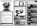
Mounting
The FDP2 should be
mounted using the
keyhole mounting
points as indicated in
the adjacent diagram.
The FDP can be
mounted horizontally
or vertically.
Ø 4.00
75.00
Ø 9.00
Basic Cable Installation
Cabling should be a minimum 0.75mm
2
throughout. Terminals TCC-NET
A/B connect to the Toshiba TCC-NET. TCC-NET installation should follow
Toshiba installation specifications. Terminals R1-R2 connect to fault
monitoring or indication equipment according to the specified rating of the
relay. The FDP2 is powered from the TCC-NET and requires no extra power
supply.
TCC-NET
Indoor Unit
To fault monitoring
TCC-NET D-BUS RELAY
A
B
D1
D2
R1
R2C
Toshiba Remote Controller
A
B
LED Functionality
Normal Operation
Key:
FLASHINGOFF ON
R
G
Power-Up sequence
Factory Configuration
R
G
No Fault State
R
G
Power-Up sequence
Custom Configuration
R
G
Unit Fault
R
G
TCC-NET Holdoff. After
power-up and during
unit configuration
Error Conditions
R
G
Device configuration error
R
G
No unit master found on TCC-Net
R
G
D-BUS Communications timeout
R
G
Duplicate D-BUS Address detected
Standard Operation
ON
SW1 SW7
ON
FDP2 Configuration Switches
The FDP2 has a number of standard configurations that can be set using
switches SW1 to SW7 shown above. Factory configuration is configured
with all switches OFF. In this mode the FDP2 operates as a standard fault
monitoring device. Additional preset modes are available using SW1 and
SW2 to operate the system in preset Heat, Cool and Auto modes*.
Fault Monitoring
8 Units max
Fault Monitoring + Locked Cooling Preset
18
8 Units max
Fault Monitoring + Locked Heating Preset
23
8 Units max
Fault Monitoring + Locked Auto Preset
21
8 Units max
*Units that do not support specific modes such as cooling-only units will operate in fan-only in unsupported
modes.
FDP2 Description
The FDP2-F is a monitoring and control interface for the Toshiba Digital
Inverter, SHRM and SMMS range of air-conditioners.
Fault Reporting
The FDP2-F Interface detects all indoor and outdoor faults occurring in
TCC-NET compatible Toshiba air-conditioners and reports them by closing
relay contacts R1-R2. The FDP2-F is connected on the TCC-NET network
with or without a standard remote controller and detects any faults that can
be displayed on the controller for up to 8 units. Red and Green LEDs
Indicate Fault/No Fault state.
Control Functions
GROUP CONTROL. Multiple FDP2 Interfaces can be connected to form
large groups of units controlled from a single remote controller.
OPERATION PRESETS. Remote controller operation can be locked and
various different preset run conditions can be sent from the FDP2.
DUTY/STANDBY. Pairs of FDPs can operate duty/standby control with 24
hour alternating duty, and changeover on fault.
HARDWIRED CONTROL. In conjuntion with an FDP2-BMS unit control can
be achieved through potentiometer and volt-free contact inputs as well as
via BMS integration.
CUSTOM CONTROL. FDP2 interfaces can be supplied in custom
configurations to suit specific applications.
Warnings and Cautions
Do not exceed the specified fault relay ratings
Ø 4.00
26.00
20.00
13.00
18.60
87.00
72.00
ALL DIMENSIONS IN MM NOT TO SCALE
ON
SW1 SW7
ON
RealTime Control Systems Ltd
FDP2 Model 9410-2-A6
63.00
Fault
No Fault
Fault Interface
FDP2-F
TCC-NET D-BUS RELAY
A
B
D1
D2
R1
R2C
Ø 9.00

9570-0 FDP2-F Installation & Operating Instructions issue 1.14.02 Copyright © RealTime Control Systems Limited. 2005
Functional Specification
Electrical Environmental
TemperatureSupply
18V DC from TCC-NET
Storage
-10oC to 50oC
Operation
0oC to 50oC
Power
<1VA
Relay
1A, 24VAC max
1A, 30VDC max
Humidity
0-90% RH
non-condensing
Mechanical
Protection
IP30
Dimensions
(mm)
H72 x W87 x D19
EMC Emissions
EN61000-6-1
EMC Immunity
EN61000-6-3
Mounting
Two keyhole mounting
flanges
Casing
Zinc coated mild steel
Weight
80g
Connectors
Rising clamp to 0.75mm
2
cable
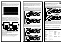
FDP2 Advanced Operation
ADDRESSING
The FDP2 has the facility to create control groups using multiple FDP2s
connected together on the D-Bus network. In standard configuration up
to 16 FDP2 devices can be connected together. Each FDP2 is assigned
a D-Bus address using the configuration switches SW4 to SW7. Unit
addresses are shown below.
ADDRESS 0
ADDRESS 1
ADDRESS 2
ADDRESS 3
ADDRESS 4
ADDRESS 5
ADDRESS 6
ADDRESS 7
ADDRESS 8
ADDRESS 9
ADDRESS 10
ADDRESS 11
ADDRESS 12
ADDRESS 13
ADDRESS 14
ADDRESS 15
Address 0 is the FDP2 MASTER address. Address 1 to 15 are FDP2
SLAVE addresses that can be used to create large control groups.
NETWORK INSTALLATION
The D-Bus network requires a twisted pair cable connecting terminals
D1 and D2 on each FDP2 as shown below. Terminal D1 must be
connected to all other D1 terminals. Terminal D2 must be connected to
all other D2 terminals. In addition the common terminal C on all devices
must be connected together. If a shielded cable is used then the shield
can be used for this purpose. The network must be installed as a point
to point BUS configuration, Star and Ring connections must NOT be
used.
TCC-NET D-BUS RELAY
A
B
D1
D2
R1
R2C
ADDRESS 0
TCC-NET D-BUS RELAY
A
B
D1
D2
R1
R2C
ADDRESS 1
D1 D1
D2 D2
C C
SPECIFICATION
Use solid or stranded 24awg shielded or unshielded twisted pair to
Cat3, Cat4 or Cat5 specification. Use a twisted pair for connections
D1,D2 and an extra core for connection C.
NETWORK LENGTH
Standard installation for total network distances of up to 500m can be
achieved following the basic daisy-chaining method showed in the
above diagram. Network layout should follow a point-to-point
connection, ‘T’ and star connections are not supported,
FDP2 Group Control
Group control allows up to 16 FDP2s to be connected on a D-Bus local
network. Each FDP2 reports faults for the locally attached units. The
FDP2 with address 0 is a MASTER and determines the settings for all
systems connected to FDP2s addressed as slaves. The operating mode
of the master is determined by SW1, SW2 as shown in the Standard
Operation configuration instructions overleaf.
LOCAL CONTROL
With SW1 OFF and SW2 OFF the MASTER FDP2 system operates under
the control of the attached remote controller. SLAVE FDP2 devices will
duplicate these settings to allow large groups to be controlled from one
remote controller. Remote controllers on the slave FDP2s are locked and
can be omitted if desired.
Address 0 (MASTER)
Address 1 (SLAVE)
D-BUS
16 FDP2 max
8 Units max
8 Units max
PRESET CONTROL
If the master is configured for Heat, Cool or Auto preset control then the
FDP2 slave units will operate to the same settings as the master. The
diagram below shows the system configured for the Cool preset. See
overleaf for SW1, SW2 settings for Heat and Auto presets.
Address 0 (MASTER)
Address 1 (SLAVE)
D-BUS
18
18
16 FDP2 max
8 Units max
8 Units max
FDP2 Duty/Standby Operation
Duty/Standby will alternately run two systems on 24 hour
alternating run/standby. If a fault occurs on either system
then both systems are switched on until the fault is
cleared.
SW3 ON for
Duty/standby
Duty/Standby is achieved using two FDP2 devices, one with Address 0
and one with Address 1 with a D-BUS connection between the two. SW3
must be switched ON on both devices to enable the operation.
Address 0 (MASTER)
Address 1 (SLAVE)
D-BUS
21
21
1 Day 1 Day 1 Day FAULTDUTY/STANDBY
16 FDP2 max
8 Units max
8 Units max
The MASTER FDP2 can be configured using SW1 and SW2 to operate
using one of the three preset modes Heat, Cool or Auto. Alternatively the
MASTER can be configured for local control, in which case the remote
controller attached to the MASTER FDP2 can be used to set the operating
settings during master duty.
Advanced control
More sophisticated control con be achieved using the FDP2-BMS
interface, this provides a number of inputs that allow external control of
unit operation, or connection to Building Management Systems. The
FDP2 interfaces can also be customised for specific operating
requirements. Contact Toshiba for details.
-
 1
1
-
 2
2


Toshiba RBC-FDP2-F-PE User manual
- Category
- Networking
- Type
- User manual
Ask a question and I''ll find the answer in the document
Finding information in a document is now easier with AI
Related papers
Other documents
-
Delta Tau PMAC PCI LITE Reference guide
-
-
-
-
Siemens TC12 User manual
-
Schneider Electric ATV71 Owner's manual
-
Eurotherm ATV71 Owner's manual
-
Haier 1UH160P1ERG User manual
-
NXP RS08LA Reference guide
-
Schneider Electric Outboard Motor FBZ2 User manual