Covers Part #8085X
Pro Scale
®
Advanced Lighting Control System Installation Instructions - TRX-4
®
Sport
TRAXXAS.com
Traxxas, 6250 Traxxas Way, McKinney, TX 75070,
HKC21014-R00 Rev 220121
Visitez Traxxas.com/manuals pour télécharger
les instructions dans votre langue.
Visite la página Traxxas.com/manuals para
descargar el instrucciones en su idioma.
Auf Traxxas.com/manuals, können Sie
anleitung in Ihrer Sprache downloaden.
CAUTION: RISK OF INJURY!
Use care with hobby knives, tapered reamers, and other cutting tools as they
are extremely sharp and can cause severe injury, deep cuts, and/or punctures.
The Traxxas Pro Scale® Advanced Lighting Control System
for your TRX-4® Sport consists of two major electronic
components: the Pro Scale Lighting Power Module and
the Pro Scale Lighting Distribution Block.
The Lighting Power Module installs on the chassis and
performs as the voltage regulator and power supply
for the lighting system. It also controls various lighting
functions through the two buttons on the face of the
module and communicates with the receiver in the model
via the communication cable or the optional included
MAXX® Link cable.
The Lighting Distribution Block mounts in the body of
the vehicle and is the distribution hub for all the various
wired lights in your
Sport
body. Its main function is to
direct power and instructions to the brake lights, reverse
lights, turn signals, and high/low beam lighting.
There is only one rugged breakaway wiring connector
between the
Lighting Distribution Block
and the
Lighting
Power Module
for reliable lighting performance, plus it
makes it easy to remove the body for vehicle service. The
connector is designed to break away from the vehicle,
without damage, if the body comes off the vehicle in a crash.
There are lighting channels on the
Lighting Power Module
which allow the lighting installed on the chassis to be
permanently connected and integrated into the system.
This is helpful to install features such as rock lights, bumper
lights, and other chassis-mounted accessory lighting.
CAUTION: RISK OF DAMAGE TO BATTERIES!
Always disconnect the battery from the ESC when not in use to prevent the
possibility of over-discharge and battery damage.
Kit Contents:
• Pro Scale Lighting
Power Module
• Power module chassis mount
• Pro Scale Lighting
Distribution Block
• Lighting Distribution
Block mount
• Motor sense wire harness
• Breakaway cable (part of the
Lighting Distribution Block)
• MAXX® Link cable (Data Link)
(TQi Radio System only)
• Receiver communication cable
• Headlights harness assembly
• Tail lights harness assembly
• Turn signal harness
• Reverse lights harness
• Front grille
• Front grille retainer
• Headlight clamps (2)
• Tailgate panel
• Tailgate panel retainer
• Tail light clamps (2)
• Reverse light lens, left & right
• Jumper
• LED front bumper light bar
high/low adapter
• LED roof light bar high/low
adapter
• 2.5x8mm button-head screws
(8)
• 2.6x8mm button-head screws
(4)
• 2.5x10mm button-head
screws (2)
• 2.5x10mm countersunk cap
screw (1)
• 2.5x12mm cap screw (1)
• 2.5x18mm cap screw (1)
• Zip ties (10)
• Zip tie mount (3)
• Body templates
• Double-sided adhesive
foam tape
• Silicone grease
Tools required:
• Safety glasses
• 2.0mm hex wrench
(part #3415, sold separately)
• 1.5mm hex wrench
(part #3415, sold separately)
• Hobby knife
• Small file (optional)
• Tapered body reamer (part
#3433 or #3433X, sold
separately)
• Body scissors (part #3431
(straight tip) or #3132 (curved
tip), sold separately)
• Rotary tool (such as Dremel®)
(optional)
• Wire cutters (to trim zip ties)
• Small needle nose pliers
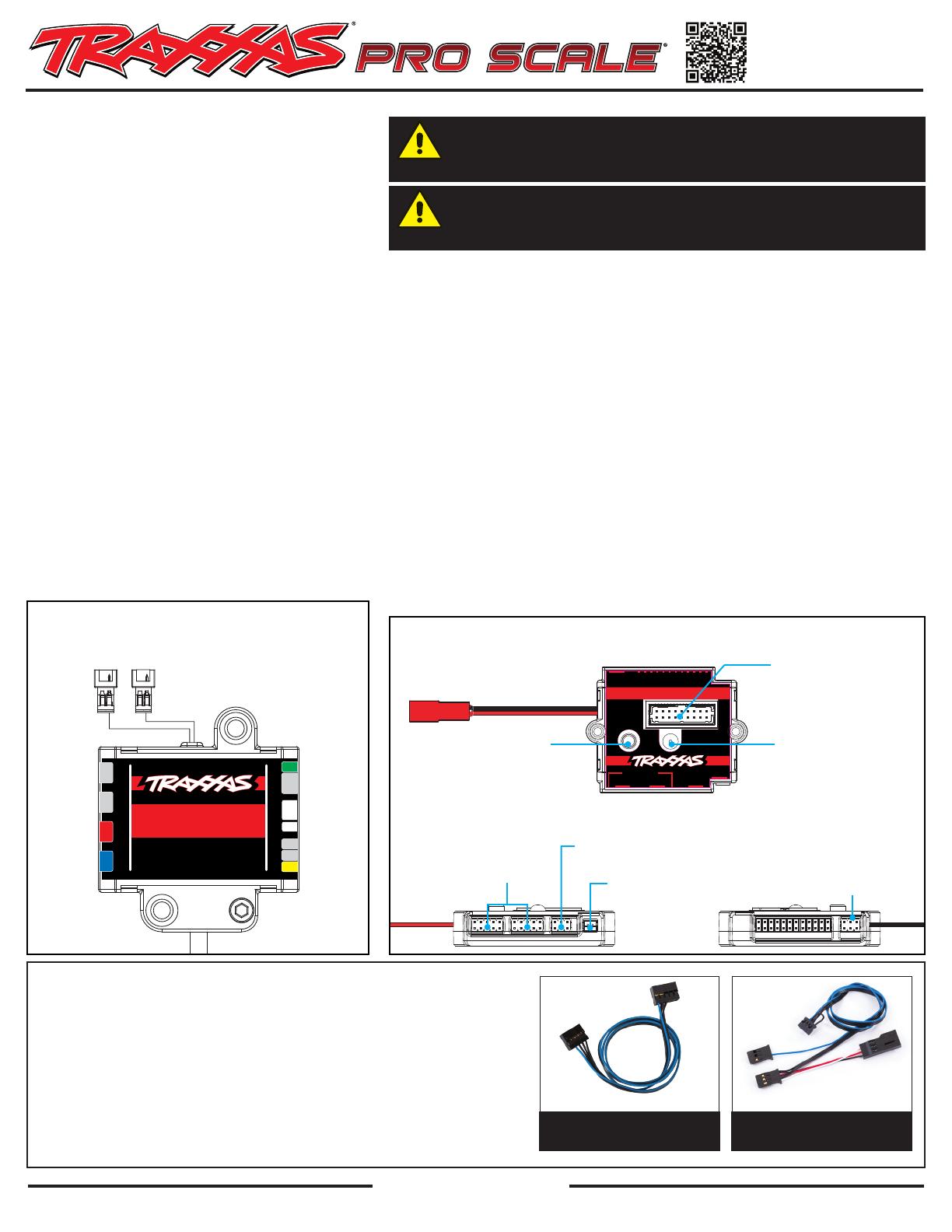
AUX
POWER
IN RX INOUT
Part 6592
1
2
3
4
5
6
7
8
9
10
11
12
MOTOR
SENSOR
MAXX LINK
SIGNAL
MODE
PRO SCALE® LIGHTING POWER MODULE
Mode Select
(see table in
Operation section)
Signal Select
(see table in
Operation section)
Breakaway Cable
Connector Port
(connects Power Module
to Lighting Distribution Block)
to Traxxas XL-5 HV Electronic
Speed Control (ESC) or direct
battery power source
up to 3s LiPo or 12.6V
Receiver Communication Cable Port
(connects power module to receiver
using receiver communication cable)
Motor Sense
Connector Port
Auxiliary Power Connector
(3V - always on)
LIGHTING POWER MODULE
TOP VIEW
SIDE VIEW
MAXX® Link Cable Ports
(connects power module to
receiver using MAXX Link cable)
(TQi Radio System only)
1
COMMUNICATION CABLES
Your Pro Scale Advanced Lighting Control System includes two communication
cables: the Receiver Communication Cable and the MAXX® Link Cable.
Since your TRX-4 Sport is factory equipped with the TQ receiver, use the Receiver
Communication Cable to connect the Lighting Power Module to the receiver.
The MAXX Link Cable is only for use on models with the TQi radio system.
The 6511 Traxxas Link Wireless Module (sold separately) is required for Traxxas
Link App functionality (only with the MAXX Link Cable). Some models may require
a software update for the TQi receiver via the Traxxas Link App for custom lighting
controls and configurations (see Appendix on page 7 for additional information).
MAXX® Link Cable
(TQi Radio System only)
Receiver Communication
Cable
PRO-SCALE
DISTRIBUTION
BLOCK
#XXXX
™
E
F
G
H
K
M
N
A
B
C
D
Part 6593
PRO SCALE® LIGHTING
DISTRIBUTION BLOCK
Wiring connectors for the lights are
labeled with letters and/or colors.
LIGHTING DISTRIBUTION BLOCK
Accessory Connectors
(not used with this kit)


