VTS Energy Recovery Wheel Motor Owner's manual
- Type
- Owner's manual

version 1.3 (08.2023)
ENERGY RECOVERY WHEEL MOTOR MANUAL
OPERATION AND MAINTANANCE

2
Please read the following documentation carefully before performing installation, maintenance and
operating of rotary heat exchangers motors. In case of doubts contact VTS official support. This manual
must only be used by a qualified installer/service technician.
TABLE OF CONTENT
1. GENERAL SAFETY ........................................................................................................................................................... 3
2. PRODUCT DESCRIPTION & TECHNICAL SPECIFICATION ................................................................................................ 3
3. INSTALLATION ............................................................................................................................................................... 6
3.1 Assembly and installation ....................................................................................................................................... 6
3.2 Connection and wiring ............................................................................................................................................ 7
3.2.1 Main voltage and stepper motor wiring ........................................................................................................ 10
3.2.2 Cable requirements ........................................................................................................................................ 12
3.3 Elements of the controller panel .......................................................................................................................... 12
3.3.1 Test button ..................................................................................................................................................... 12
3.3.2 Dip switch ....................................................................................................................................................... 12
3.3.3 LED Indicator .................................................................................................................................................. 13
3.4 Modbus control ..................................................................................................................................................... 14
3.5 Adaptation of the new OI RRG controller (SPR) to work with VTS AHU ............................................................... 17

3
1. GENERAL SAFETY
CAUTION! Electric Voltage: All motors described in the following manual can be operated,
connected, installed, repaired and modified by qualified personnel only. Failure in performing in any
of this operations may result in risk of fatal injury, electric shock, incorrect mounting or product
damage. Installation should be carried out with usage of power lines, without short circuits and with
proper grounding. Follow the connection diagrams dedicated to given motors.
WARNING: Do not open or disassemble the motor while power supply is connected to the device. It may result in fatal
injury caused by electric shock. If it is necessary to open the motor, wait at least 5 minutes after disconnecting from
the power supply.
NOTE: It is the user and the installer responsibility to provide the system with the proper grounding and protection in
accordance with national and local standards. VTS is not responsible for any damages or injuries caused by incorrect
installation, bad circuits or other failures.
Before installation and operating the motor please read entire instruction carefully! Follow the connection
diagrams to perform successful installation.
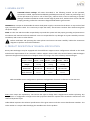
2. PRODUCT DESCRIPTION & TECHNICAL SPECIFICATION
Rotary Heat Exchangers may be equipped with three different stepper motors configurations tailored to the needs
and electrical requirements of our customers. Table 1 Stepper motors used in the series of Rotary Heat Exchangers
represents the general characteristics of stepper motors occurring in the series of Rotary Heat Exchangers.
Torque - Power
2.0 Nm – 55W
4.0 Nm – 110W
8.0 Nm – 260 W
Weight
≈ 2.4 kg
≈ 3.5 kg
≈ 5.0 kg
Dimensions
85 x 85 x 67
85 x 85 x 97
85 x 85 x 156
Shaft diameter
12 mm
12 mm
12 mm
Table 1 Stepper motors used in the series of Rotary Heat Exchangers
Table 2 Available motor configurations represents configuration of motors in reference to the AHU size.
Motor
AHU Size
2 Nm – 55 W
VVS021-VVS055
4 Nm – 110 W
VVS075-VVS300
8 Nm – 260 W
VVS150-VVS300
Table 2 Available motor configurations
Note: Given setups are explanatory. VTS reserves the right to change those configurations without informing. Any
modification or configuration changes other than proposed should be reported and consulted in details with VTS
technical department first.
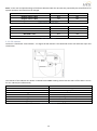
Tables below represent the technical specifications of the given motors with the correct identification numbers. The
index number is a unique code identifying the suitable motor for the product.

4
Torque
2.0 Nm
4.0 Nm
8.0 Nm
INDEX NUMBER
7-1-0005-0082
7-1-0002-0083
7-1-0005-0084
PH
1
1
1
Voltage [V]
208-240
208-240
208-240
Stepper motor voltage [V]
3 x 0-200 V
3 x 0-200 V
3 x 0-200 V
RPM
0-400
0-400
0-400
Frequency [Hz]
50
50
50
HP
0,08
0,15
0,36
Power size (250 rpm)
55 W
110 W
260 W
Weight
≈ 2.4 kg
≈ 3.5 kg
≈ 5.0 kg
Sealing grade [IP]
54
54
54
Operating temperature
-40˚C to +40˚C
-40˚C to +40˚C
-40˚C to +40˚C
Storage temperature
-40˚C to +70˚C
-40˚C to +70˚C
-40˚C to +70˚C
Dimensions
85 x 85 x 67
85 x 85 x 97
85 x 85 x 156
Shaft diameter
12 mm
12 mm
12 mm
Electrical connection
4-pole Tyco MATE-N-LOK
4-pole Tyco MATE-N-LOK
4-pole Tyco MATE-N-LOK
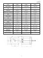
Table 3 Technical specification of available motor setups
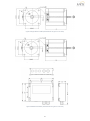
Figure 1 Stepper Motor 2.0 Nm (all dimensions are given in mm units)

5
Figure 2 Stepper Motor 4.0 Nm (all dimensions are given in mm units)
Figure 3 Stepper Motor 8.0 Nm (all dimensions are given in mm units)
Figure 4 Dedicated controller (all dimensions are given in mm units)

6
3. INSTALLATION
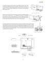
3.1 Assembly and installation
Following illustrations and instructions presents the correct assembling of the motors and controller with the casing
of the rotary heat exchanger. Motors are designated to be firmly attached to casing of the exchanger. Pulleys are
selected to match the expected speed, efficiencies and performance of the motors. Please refer to the Chapter 2 -
Product Description and Technical Specification to determine the correct set of components for the product. Pulley
wheels must be firmly attached to the shaft of the motor.
Do not change the motor configurations. Follow the correctly selected setup given in the first chapter
of this manual (see Table 2). Changing the settings is associated with poor performance of the rotary
wheel and risk of incorrect attachment to the housing of the exchanger, and most importantly, the risk
of motor damage, as well as electric shock due to incorrect connection.
Warning: Incorrect mechanical installation of the motor can be a cause of error alerts.
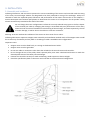
Following illustrations represents stepper motor assembly and installation methods. Each of the stepper motor model
has its own way of assembly and may differ in according to Table 2 Available motor configurations.
Important notes:
Stepper motor must be fixed firmly to a casing via dedicated motor holder.
Stepper motor must be grounded.
Do not use cables or connectors other than that included in the set with motor and controller.
Do not change the size of the pulley wheel. Optimal pulley sizes were calculated and chosen to match the
desired performance of the Rotary Heat Exchanger.
Position the controller correctly to avoid overheating. Avoid exposure to direct sunlight.
Check the specification plate on the motor and controller to confirm electrical configuration.
Figure 5 Stepper Motor 2Nm assembly schematic

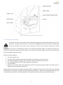
7
Figure 6 Stepper Motor 4Nm and 8Nm assembly schematic
3.2 Connection and wiring
To perform the correct setup, please refer to the following diagrams representing possible ways of motor
connection. Installation and connection can be done by qualified personnel only. Failure in performing in
any of this operations may result in risk of fatal injury, electric shock, incorrect mounting or product
damage.
WARNING: Do not open or disassemble the motor nor controller while power supply is connected to the device. It
may result in fatal injury caused by electric shock. If it is necessary to open the motor, wait at least 5 minutes after
disconnecting from the power supply.
Notes on proper installation:
Use fuses at power line.
Check the wires condition before operating. Make sure that there are no short circuits.
Use cables fulfilling the voltage, current, load and insulation installation requirements.
Use only high quality hard wire or fiber copper wire with ferrule.
Use shield cable.
Make sure that motor label plate specification matches the operating supply voltage. Use cables that are
adapted to work with the desired current.
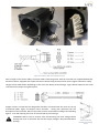
Stepper motors used in series of VTS Heat Exchangers (Figure 7 Stepper motor with male type terminal) are connected
and powered via controller responsible for basic operational parameters. Motor itself is equipped with male type
terminal which characteristic are described below in the Figure 8 Connection cable with dedicated terminal.

8
Figure 7 Stepper motor with male type terminal
Figure 8 Connection cable with dedicated terminal
Due to length of the motor cables, extension cables connecting motor with the controller are supplied additionally.
Extension cable is equipped with 4 pole connectors sleeves fitting terminal of the motors (Figure 9 Extension cable).
Lengths of the cables differs depending on the size of the Rotary Heat Exchanger. Figure below represents the cable
connection with proper wiring description.
Figure 9 Extension cable
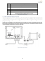
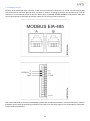
Stepper motors are operated via designated controller connected with the motor by the up
mentioned cables. Figure 14 Stepper motor controller - wiring slots represents the slot
description of the controller. Wires of the motor must be connected according to the following
figures - start with opening the cover of the controller by unscrewing it.
WARNING! Wait at least 3 minutes after disconnecting the main voltage before
opening the cover of controller. Be sure that supply voltage is disconnected before
opening.
Figure 10 Opening
controller by removing
screws

9
To make the wiring process easier it is possible to remove the cover
completely by detaching it from the controller. It will provide an easy access
to the wiring slots. Hinged brackets allow to detach the doors by light pull
(Figure 11 Controller cover). Despite that, cover doors can be opened at
approximately 135°.
Electronic circuits of the controller (PCB) is protected by additional plastic
cover (Figure 12 PCB cover) - it is forbidden to remove by unqualified
personnel. This cover can be opened only to perform specialized service
repairs. Do not attempt to perform any repairs by your own. Manufacturer
warranty will not be void until the cover has traces of opening.
Controller is equipped with spring terminals to make the installation faster. Spring-loaded
terminal allows to easily insert the wire into the desired slot by pushing it inside – no tools
required. It is compatible with an multi-core cables/leads with additional core sleeves/end
sleeves. Maximum and minimum dimensions of the wires are given in the Table 5. Wire
ends or end sleeves must be between 8 – 10 mm. To detach the wire – press the terminal
carefully with the screwdriver.
Figure 14 Stepper motor controller - wiring slots
Figure 11 Controller cover
Figure 12 PCB cover
Figure 13 Spring terminals

10
No.
Description
1
Test button
2
4-pole DIP switch
3
LED
4
Display – not used in base VTS automation
5
RJ12 Modbus connector (2 x RJ12)
6
A/D control and signal terminals, depending on version
7
Supply terminals (L, N, PE)
8
Connection terminals for stepper motor (U, V, W, PE)
Table 4 Controller slots description
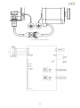
3.2.1 Main voltage and stepper motor wiring
The power supply of the controller is 230V AC; +/- 10%. Cable of the power supply should be connected on the
terminals marked with letters “L”, “N” and “PE” (see Figure 15 Power supply connection). Cables should be inserted
via dedicated cable entries/glands. After the wiring is performed, remember to re-tighten the cable glands and avoid
pulling out or twisting.
Stepper motor is assembled with the integrated cable and connected to the controller via dedicated extension cable.
Both of them are ended with the 4-pole connectors allowing for quick connection. Locking pawl of terminals will ensure
the firm installation of both cables. Do not shorten the cables.
Figure 15 Power supply connection

11
Figure 16 Stepper motor connection
Figure 17 Controller schematic

12
3.2.2 Cable requirements
Before performing the installation, make sure that your setup fulfills the following list of requirements:
All cables and leads must comply with the local and national regulations.
Cable dimensions for PG9 connectors should be within the range of 3-8mm
Cables meet the dimension requirements given in the Table 5.
Copper wires are recommended.
Modbus cable can be 6-wire unshielded, 30 AWG/0,066 m2 or similar.
Control wires and cables
Minimal Conductor
Dimension
Maximum Conductor
Dimension
Cable dimension
Solid wires
0.08 mm2
1.5 mm2
3-8 mm
Multi-core wires
0.14 mm2
1.0 mm2
3-8 mm
Power leads and cables
Solid wires
0.2 mm2
4.0 mm2
3-8 mm
Multi-core wires
0.2 mm2
2.5 mm2
3-8 mm
Table 5 Cable and wires dimension requirements
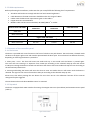
3.3 Elements of the controller panel
3.3.1 Test button
The driver is provided with a test function in the form of a built-in test push-button. The test button is located inside
the drive in the upper right corner and must be operated with the drive open. The test button has different functions,
depending on how long the button is pressed in:
1. Short press < 1sec.: The drive will enter test mode and stay in test mode until the button is pressed again.
The rotor will start rotating in a sequence from 0–100 rpm according to the selected ramp-up time and remain
at 100 rpm. Pressing the button a second time will cause the drive to leave test mode and stop the rotor according to
the selected ramp-down time.
2. Pressing and holding the button will cause the drive to enter test mode where it will remain until the button is
released. The signal to the rotor will override to 100 rpm according to the selected ramp-up time.
Please note, that when pressing the test button for more than 20 sec. the calibration function off the internal
rotorguard may be triggered.
The test button also works when Modbus control is activated.
3.3.2 Dip switch
The driver is equipped with 4 DIP switches for setting the stepper motor size (see Table 6) and maximum motor speed
(Table 7).
Figure 18 DIP switch

13
Note – motor size and speed settings of the device delivered with the VTS AHU are prepared by the manufacturer for
optimal operation and should not be changed.
DIP1
DIP2
Stepper motor = 2Nm
OFF
OFF
Stepper motor = 4Nm
ON
OFF
Stepper motor = 8Nm
OFF
ON
Table 6 Stepper motor size setting
DIP3
DIP4
Max RPM = 250
OFF
OFF
Max RPM = 200
ON
OFF
Max RPM = 170
OFF
ON
Max RPM = 150
ON
ON
Table 7 Max RPM settings
3.3.3 LED Indicator
The driver is fitted with a LED indicator - see Figure 19 LED indicator. The LED diode can be seen with both open and
closed cover.
Figure 19 LED indicator
The statuses of the indicator are shown in Table 8 below. Note: Flashing means that the LED is off for 100 ms and on
for min. 100 ms (ms=milliseconds).
LED
State
OFF
No voltage
Green ON
Voltage is present
Flashing green
Valid Modbus communication
Red ON
Rotor stopped due to critical alarm
Flashing red
Operating with reduced power
Orange ON
Test function activated
Flashing orange
Purging function activated
Table 8 LED indicator statuses

14
3.4 Modbus control
Modbus can be connected to the controller via the two RJ12 connectors (connectors "A" and "B" are internally parallel
connected and it is therefore optional which connector is used) or via spring terminals in the terminal strip. For RJ12
connectors, we recommend the use of telecom cable, 6-wire, unshielded, 30 AWG/0.066mm² (flat/telecom cable) and
round communications cable (like twisted pair cables) for the spring terminal connectors.
Figure 20 RJ12 Modbus connectors
Figure 21 Spring terminal Modbus connector
After 10 seconds without receiving a valid Modbus request with the default parameters, the controller will try to detect
a Modbus request with the alternative parameters (see Table 13 to see which registers are responsible for alternative
communication parameters).

15
The default values of the parameters responsible for the communication between the controller and AHU are
unchangeable - only the alternative parameters are to be changed.
Note - the settings of the device delivered with the VTS AHU are prepared by the manufacturer for optimal operation
and should be changed only in justified cases.
Function code
Description
1
Read Coil Status
2
Read Input Status
3
Read Holding Registers
4
Read Input Registers
5
Force Single Coil
6
Preset Single Registers
8
Diagnostics. Sub-function 00 Only – Return Query Data (loop back)
15
Force Multiple Coils
16
Preset Multiple Registers
Table 9 Available functions
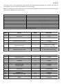
Adress
Function
Range
Active state
0
Motor ON/OFF
0 - 1
1 = ON
1
Reset Alarms
0 - 1
1 = Reset
3
Rotation direction
0 - 1
1 = CounterClockWise
8
Use altern. comm. settings
0 - 1
1 = Alternative
12
Disable internal rotor guard
0 - 1
1 = Disabled
13
Enable external rotor guard
0 - 1
1 = Enabled
14
High speed resolution
0 - 1
0 = Resolution = 0.1 RPM
1 = Resolution = 0.01 RPM
15
K-factor for Modbus
0 - 1
1 = K-factor not used for Modbus
16
Enable auto saving of UDF
0 - 1
1 = UDF stored automatically
Table 10 Available Coil Statuses
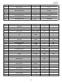
Adress
Function
Range
Active state
0
Rotorguard Alarm
0 - 1
1 = Alarm
1
V LO Alarm
0 - 1
1 = Alarm
2
V HI Alarm
0 - 1
1 = Alarm
3
I HI Alarm (Motor out short)
0 - 1
1 = Alarm
4
Temperature High
0 - 1
1 = Warning
8
Rotorguard Signal
0 - 1
1 = Pulse
9
Overload / I_Limit
0 - 1
1 = Warning
10
Internal Stop
0 - 1
1 = Alarm (Stop)
11
Rotor Blocked
0 - 1
1 = Alarm
12
EEPROM error
0 - 1
1 = Warning
13
Communication error MOC
0 - 1
1 = Alarm
14
Motor Phase Error
0 - 1
1 = Alarm
15
Ripple
0 - 1
1 = Warning

16
16
Digital Input 1
0 - 1
1 = HI
17
Digital Input 2
0 - 1
1 = HI
18
Ext. 24V supply overload
0 - 1
1 = Overload
19
MOC in bootloader
0 - 1
1 = Alarm
22
Communication error IOM
0 - 1
1 = Warning
23
Rotation OK
0 - 1
1 = OK
24
Test function active
0 - 1
1 = Active
25
Purging active
0 - 1
1 = Active
26
IO Config mismatch
0 - 1
1 = Warning
Table 11 Available Input Statuses
Adress
Function
Range
Resolution
Unit
0
DHX Type
0 - 14
1
-
1
AOC SW version
0 - ?
0.01
-
2
PrcOut
0 - 10000
0.01
%
3
Intern Temp
-5000 - 15000
0.01
ºC
4
Motor Speed Out
0 - 40000
0.01
RPM
5
V In
0 - 300
1
V
6
I Out (RMS)
0 - 10000
1
mA
7
Power In
0 - 1000
1
W
8
ExternSet
0 - 10000
1
mV
9
Operation Day
0 - 9999
1
Day
10
Operation Minutes
0 - 1439
1
Min.
11
I Ripple
0 - 10000
1
mA
12
V Ripple
0 - 100
1
V
13
Config file variant
AA - ZZ
2 ASCII characters
14
Config file version
100 - 32000
0.01
-
15
MOC SW version
0 - ?
0.01
-
16
Rotor Speed Out
0 - 40000
0.01
RPM
17
Torque
0 - 1500
0.01
Nm
17
SW variant
-
-
-
18
AOC Boot SW
0 - ?
0.01
-
19
MOC Boot SW
0 - ?
0.01
-
20
Motor Cfg. Var.
0 - 65535
1
-
21
Motor Cfg. Ver.
0 - 65535
0.01
-
22
Rotor Cfg. Var.
0 - 65535
1
-
23
Rotor Cfg. Ver.
0 - 65535
0.01
-
24
User Data Var.
0 - 65535
1
-
25
User Data Ver.
0 - 65535
0.01
-
26
IOM SW version
0 - ?
0.01
-
27
V DC Bus (Peak)
0 – 400
1
V
28
V Motor (Peak)
0 – 400
1
V
29
ExternSet2 (IOM)
0 - 10000
1
mV
Table 12 Available Input Registers

17
Adress
Function
Range
Resolution
Unit
0
Setpoint / PrcSet
0 - 10000
0.01
%
1
Min. Motor Speed
100 - Max.
0.01
RPM
2
Max. Motor Speed
Min. - 40000
0.01
RPM
3
Start I Out (Boost)
0 - ?
1
mA (RMS)
4
Start Time (Boost)
0 - ?
1
Sec.
8
Prc Holding Torque
0 - 1000
0.1
% of max
9
UpRampTime
15 - 300
1
Sec.
10
DownRampTime
15 - 300
1
Sec.
11
SwitchMode
0
(Auto)
1
8
kHz
2
10
kHz
12
DHX Type
0 - ?
1
-
13
Alternative Modbus ID
1 - 247
1
-
14
Alternative BaudRate
0
9600
bps
1
19200
bps
2
38400
bps
3
57600
bps
4
115200
bps
15
Alternative Parity
0
None
-
1
Odd
-
2
Even
-
16
Alternative Stop Bits
0
INVALID
-
1
1
-
2
2
-
17
Number of retries
-1 - 100
1
-
18
Modbus Timeout
0 - 240
1
Sec.
19
Pulley size (diameter)
0 - 1000
1
mm.
20
Rotor size (diameter)
0 - 10000
1
mm.
21
Pulses per rotation
0 - 10
1
-
22
K factor
0-10000
-
-
Table 13 Available Holding Registers
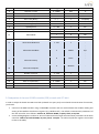
3.5 Adaptation of the new OI RRG controller (SPR) to work with VTS AHU
In order to adapt the brand new RRG controller (ordered as a spare part) to work with the automation of VTS AHUs,
you should:
connect to the RRG controller using a USB-RS485 converter and a PC with software that enables reading and
writing of the Modbus slave devices registers (e.g. Modbus Poll) - the default communication parameters of
the new controller are as follows: address 79, baudrate 38400, no parity check, 2 stop bits
set the Holding Registers number 13-16 in accordance with the target communication parameters of the uPC3
controller: address 4, baudrate 9600, no parity check, 1 stop bit - see Table 13 (relevant registers are marked
in blue in the table)

18
Access to the registers of the rotary exchanger controller settings is done without the use of a password. The password
is also not required to save the settings after they have been changed.
To enable uPC3 - RRG OI cooperation, the RRG motor type selected on the I03 configuration screen of the uPC3
controller must be set to OI.
-
 1
1
-
 2
2
-
 3
3
-
 4
4
-
 5
5
-
 6
6
-
 7
7
-
 8
8
-
 9
9
-
 10
10
-
 11
11
-
 12
12
-
 13
13
-
 14
14
-
 15
15
-
 16
16
-
 17
17
-
 18
18


VTS Energy Recovery Wheel Motor Owner's manual
- Type
- Owner's manual
Ask a question and I''ll find the answer in the document
Finding information in a document is now easier with AI
Related papers
Other documents
-
FläktGroup DRHX Controller for Rotary heat exchanger Installation and Maintenance Manual
-
OJ Electronics OJ-DRHX-MRHX-1-8Nm Operating instructions
-
-
-
Trox X-CUBE Operating instructions
-
-
Swegon TAC6 Maintenance Manual
-
-
LS G100 User manual
-