Page 4 Eaton
4.0 Specications
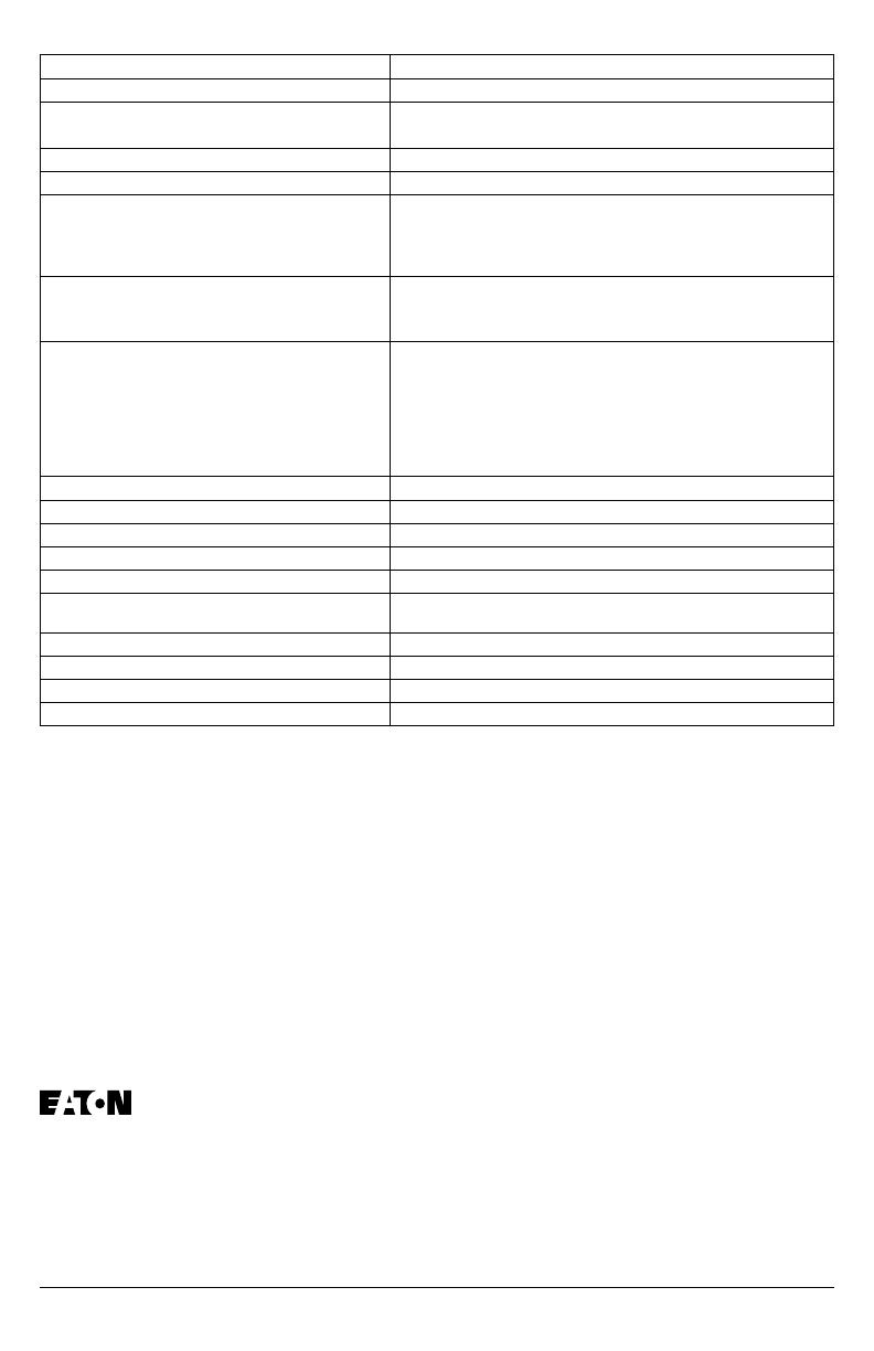
Description Ratings
Surge current capacity per phase 50kA
Nominal Discharge Current (In) 20kA for SP1-240S, 208Y, 480Y, 240D, and 480D, 10kA for
SP1-600Y and 600D
Short circuit current rating (SCCR) 200kA
SPD type Type 1 (can also be used in Type 2 applications)
System voltages available (VAC)
Single split-phase
Three-phase wye
Three-phase delta
120/240
120/208, 277/480, 347/600
240, 480, 600
Protection modes
Single split-phase and three-phase wye
Three-phase delta
L-N, L-L
L-G, L-L
Maximum continuous operating voltage (MCOV)
SP1-240S and SP1-208Y 150 L-N, 300 L-L
SP1-480Y 320 L-N, 640 L-G
SP1-600Y 420 L-N, 840 L-G
SP1-240D 300 L-G, 300 L-L
SP1-480D 640 L-G, 640 L-L
SP1-600D 840 L-G, 840 L-L
Input power frequency 50/60 Hz
Enclosure rating NEMA 4
Operating temperature -20°C through 50°C (-4°F through 122°F)
Operating humidity 5% through 95%, noncondensing
Operating altitude Up to 16,000 ft (5000m)
Agency certification and approvals UL1449 4th Edition Type 1 and Type 2 SPD
CSA-22.2 No. 269.1-17 2nd Edition
Warranty 2 years
UL 96A Compliant Yes
NFPA 780 Compliant Yes
Wire Length and AWG Factory prewired with 24 inches of 12 AWG wire
to give any advice or recommendations by Eaton
shall not constitute any warranty by or impose
any liability upon Eaton. The foregoing constitutes
the sole and exclusive liability of Eaton AND IS
IN LIEU OF ANY AND ALL OTHER WARRAN-
TIES EXPRESSED, IMPLIED OR STATUTORY
AS TO THE MERCHANTABILITY, FITNESS FOR
PURPOSE SOLD, DESCRIPTION, QUALITY,
PRODUCTIVENESS OR ANY OTHER MATTER.
In no event shall Eaton be liable for special or con-
sequential damages or for delay in performance
of the warranty. This warranty does not apply if
the product has been misused, abused, altered,
tampered with, or used in applications other than
specied on the nameplate. At the end of the war-
ranty period, Eaton shall be under no further war-
ranty obligation expressed or implied. The product
covered by this warranty certicate can only be
repaired or replaced by the factory. For help on
troubleshooting the SPD, or for warranty informa-
tion, call 1-800-809-2772, Option 4, sub-option 2.
Repair or replacement units will be returned col-
lect. If Eaton nds the return to be a manufacturer’s
defect, the product will be returned prepaid.
Eaton
1000 Cherrington Parkway
Moon Township, PA 15108-44312
USA
Eaton.com
For Technical Support please call:
1-800-809-2772
© Eaton
All Rights Reserved
5.0 Warranty
Eaton warrants these products for a period of 2
years from the date of delivery to the purchaser
to be free from defects in both workmanship and
materials. Eaton assumes no risk or liability for
results of the use of the products purchased from
it, including but without limiting the generality of
the foregoing: (1) The use in combination with
any electrical or electronic components, circuits,
systems, assemblies, or any other materials or
substances; (2) Unsuitability of any product for use
in any circuit or assembly. Purchaser’s rights under
the warranty shall consist solely of requiring Eaton
to repair, or at Eaton’s sole discretion, replace, free
of charge, F.O.B. factory, and defective items re-
ceived at said factory within said term determined
by Eaton to be defective. The giving of or failure


