Page is loading ...

1
DDR2 Device Operations & Timing Diagram
DDR2 SDRAM
Device Operation
&
Timing Diagram

2
DDR2 Device Operations & Timing Diagram
Contents
1. Functional Description
1.1 Simplified State Diagram
1.2 Basic Function & Operation of DDR2 SDRAM
1.2.1 Power up and Initialization
1.2.2 Programming the Mode and Extended Mode Registers
1.2.2.1 DDR2 SDRAM Mode Register (MR)
1.2.2.2 DDR2 SDRAM Extended Mode Register
1.2.2.3 Off-Chip Driver(OCD) Impedance Adjustment
1.2.2.4 ODT(On Die Termination)
1.3 Bank Activate Command
1.4 Read and Write Command
1.4.1 Posted CAS
1.4.2 Burst Mode Operation
1.4.3 Burst Read Command
1.4.4 Burst Write Operation
1.4.5 Write Data Mask
1.5 Precharge Operation
1.6 Auto Precharge Operation
1.7 Refresh Commands
1.7.1 Auto Refresh Command
1.7.2 Self Refresh Command
1.8 Power Down
1.9 Asynchronous CKE LOW Event
1.10 No Operation Command
1.11 Deselect Command
2. Truth Tables
2.1 Command Truth Table
2.2 Clock Enable(CKE) Truth Table for Synchronous Transistors
2.3 Data Mask Truth Table
3. Maximum DC Ratings
3.1 Absolute Maximum DC Ratings
3.2 Operating Temperature Condition
4. AC & DC Operating Conditions
4.1 DC Operation Conditions
4.1.1 Recommended DC Operating Conditions(SSTL_1.8)
4.1.2 ODT DC Electrical Characteristics
4.2 DC & AC Logic Input Levels
4.2.1 Input DC Logic Level
4.2.2 Input AC Logic Level
4.2.3 AC Input Test Conditions
4.2.4 Differential Input AC Logic Level
4.2.5 Differential AC output parameters
4.2.6 Overshoot / Undershoot Specification
4.3 Output Buffer Levels
4.3.1 Output AC Test Conditions
4.3.2 Output DC Current Drive
4.3.3 OCD default chracteristics
4.4 Default Output V-I Characteristics
4.4.1 Full Strength Default Pulldown Driver Characteristics

3
DDR2 Device Operations & Timing Diagram
Self
Idle
Setting
EMR
Bank
Precharging
Power
Writing
ACT
RDA
Read
SRF
REF
CKEL
(E)MR
CKEH
CKEH
CKEL
Write
Automatic Sequence
Command Sequence
RDA
WRA
Read
PR, PRA
PR
Refreshing
Refreshing
Down
Power
Down
Active
with
RDA
Reading
with
WRA
Active
Precharge
Reading
Writing
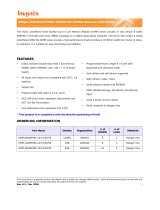
PR(A) = Precharge (All)
(E)MR = (Extended) Mode Register
SRF = Enter Self Refresh
REF = Refresh
CKEL = CKE LOW, enter Power Down
CKEH = CKE HIGH, exit Power Down, exit Self Refresh
ACT = Activate
WR(A) = Write (with Autoprecharge)
RD(A) = Read (with Autoprecharge)
Note: Use caution with this diagram. It is intended to provide a floorplan of the possible state transitions
1.1 Simplified State Diagram
All banks
precharged
Activating
CKEH
Read
Write
CKEL
MR
CKEL
Sequence
Initialization
OCD
calibration
CKEL
CKEL
CKEL
AutoprechargeAutoprecharge
PR, PRA
PR, PRA
and the commands to control them, not all details. In particular situations involving more than one bank,
enabling/disabling on-die termination, Power Down entry/exit, timing restrictions during state transitions,
1. Functional Description
- among other things - are not captured in full detail
WRA
Write
Figure 1. DDR2 SDRAM simplified state diagram

4
DDR2 Device Operations & Timing Diagram
1.2 Basic Function & Operation of DDR2 SDRAM
Read and write accesses to the DDR2 SDRAM are burst oriented; accesses start at a selected location and
continue for a burst length of four or eight in a programmed sequence. Accesses begin with the registration of
an Active command, which is then followed by a Read or Write command. The address bits registered coinci-
dent with the active command are used to select the bank and row to be accessed (BA0-BA2 select the bank;
A0-A15 select the row). The address bits registered coincident with the Read or Write command are used to
select the starting column location for the burst access and to determine if the auto precharge command is to
be issued.
Prior to normal operation, the DDR2 SDRAM must be initialized. The following sections provide detailed infor-
mation covering device initialization, register definition, command descriptions and device operation.
1.2.1 Power up and Initialization
DDR2 SDRAMs must be powered up and initialized in a predefined manner. Operational procedures other
than those specified may result in undefined operation.
Power-up and Initialization Sequence
The following sequence is required for POWER UP and Initialization.
1. Apply power and attempt to maintain CKE below 0.2*VDDQ and ODT
*1
at a LOW state (all other inputs
may be undefined.)
- VDD, VDDL and VDDQ are driven from a single power converter output, AND
- VTT is limited to 0.95 V max, AND
- Vref tracks VDDQ/2.
or
- Apply VDD before or at the same time as VDDL.
- Apply VDDL before or at the same time as VDDQ.
- Apply VDDQ before or at the same time as VTT & Vref.
at least one of these two sets of conditions must be met.
2. Start clock and maintain stable condition.
3. For the minimum of 200
us after stable power and clock(CK, CK), then apply NOP or deselect & take
CKE HIGH.
4. Wait minimum of 400ns then issue precharge all command. NOP or deselect applied during 400ns
period.
5. Issue EMRS command to EMR(2). (To issue EMRS command to EMR(2), provide “LOW” to BA0 and
BA2, “HIGH” to BA1.)
*2
6. Issue EMRS command to EMR(3). (To issueEMRS command to EMR(3), provide “LOW” to BA2, “HIGH”
to BA0 and BA1.)
*2
7. Issue EMR to enable DLL. (To issue "DLL Enable" command, provide "LOW" to A0, "HIGH" to BA0 and
"LOW" to BA1-2 and A13~A15. And A9=A8=A7=LOW must be sued when issuing this command)
8. Issue a Mode Register set command for “DLL reset”.
(To issue DLL reset command, provide "HIGH" to A8 and "LOW" to BA0-2, and A13~15.)
9. Issue precharge all command.
10. Issue 2 or more auto-refresh commands.
11. Issue a mode register command with LOW to A8 to initialize device operation. (i.e. to program operating
parameters without resetting the DLL.)
12. At least 200 clocks after step 8, execute OCD Calibration ( Off Chip Driver impedance adjustment ).

5
DDR2 Device Operations & Timing Diagram
If OCD calibration is not used, EMR OCD Default command (A9=A8= A7=1) followed by EMR OCD Calibra-
tion Mode Exit command (A9=A8=A7=0) must be issued with other operating parameters of EMR.
13. The DDR2 SDRAM is now ready for normal operation.
*1) To guarantee ODT off, VREF must be valid and a LOW level must be applied to the ODT pin.
*2) Sequence 5 and 6 may be performed between 8 and 9.
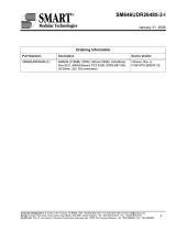
1.2.2 Programming the Mode and Extended Mode Registers
For application flexibility, burst length, burst type, CAS latency, DLL reset function, write recovery time(WR)
are user defined variables and must be programmed with a Mode Register Set(MRS) command. Additionally,
DLL disable function, driver impedance, additive CAS latency, ODT(On Die Termination), single-ended
strobe, and OCD(off chip driver impedance adjustment) are also user defined variables and must be pro-
grammed with an Extended Mode Register Set (EMRS) command. Contents of the Mode Register(MR) or
Extended Mode Registers(EMR(#)) can be altered by re-executing the MRS and EMRS Commands. Even if
the user chooses to modify only a subset of the MR or EMR(#) variables, all variables within the addressed
register must be redefined when the MRS or EMRS commands are issued.
MR, EMR and Reset DLL do not affect array contents, which means reinitialization including those can be
executed any time after power-up without affecting array contents.
Initialization Sequence after Power Up
/CK
CK
CKE
Command
PRE
ALL
PRE
ALL
EMR
MR REF
REF
MR EMR
EMR
ANY
CMD
DLL
ENABLE
DLL
RESET
OCD
Default
OCD
CAL. MODE
EXIT
Follow OCD
Flowchart
400ns
tRFC
tRFC
tRP
tRP
tMRD
tMRD
tMRD
tOIT
min. 200 Cycle
NOP
ODT
tCL
tCH
tIS
tIS
Figure 2. Initialization sequence after power-up

6
DDR2 Device Operations & Timing Diagram
1.2.2.1 DDR2 SDRAM Mode Register (MR)
The mode register stores the data for controlling the various operating modes of DDR2 SDRAM. It controls
CAS
latency, burst length, burst sequence, test mode, DLL reset, WR and various vendor specific options to
make DDR2 SDRAM useful for various applications. The default value of the mode register is not defined,
therefore the mode register must be programmed during initialization for proper operation. The mode register
is written by asserting LOW on CS
, RAS, CAS, WE, BA0 and BA1, while controlling the state of address pins
A0 ~ A15. The DDR2 SDRAM should be in all bank precharge with CKE already HIGH prior to writing into the
mode register. The mode register set command cycle time (tMRD) is required to complete the write operation
to the mode register. The mode register contents can be changed using the same command and clock cycle
requirements during normal operation as long as all banks are in the precharge state. The mode register is
divided into various fields depending on functionality. Burst length is defined by A0 ~ A2 with options of 4 and
8 bit burst lengths. The burst length decodes are compatible with DDR SDRAM. Burst address sequence type
is defined by A3, CAS
latency is defined by A4 ~ A6. The DDR2 doesn’t support half clock latency mode. A7
is used for test mode. A8 is used for DLL reset. A7 must be set to LOW for normal MR operation. Write recov-
ery time WR is defined by A9 ~ A11. Refer to the table for specific codes.
Address Field
CAS Latency
A6 A5 A4 Latency
0 0 0 Reserved
0 0 1 Reserved
0 1 0 2(optional)
011
3(speed bin
determined)
*3
100 4
101
5(speed bin
determined)
*3
110
6(speed bin
determined)
*3
1 1 1 Reserved
A7 mode
0Normal
1Test
A3 Burst Type
0 Sequential
1 Interleave
A8 DLL Reset
0No
1Yes
Mode Register
BA
1
BA
0
A
11
A
10
A
9
A
8
A
7
A
6
A
5
A
4
A
3
A
2
A
1
A
0
0
TM CAS
Latency BTDLL
0*
1
WR
Write recovery for autoprecharge
A11 A10 A9 WR(cycles)
0 0 0 Reserved
001 2
010 3
011 4
100 5
101 6
1 1 0 Reserved
1 1 1 Reserved
A
15
~ A
13
0
Burst Length
Burst Length
A2 A1 A0 BL
0104
0118
*1 : BA2 and A13~A15 are reserved for future use and must be programmed to 0 when setting the mode register.
*2: For DDR2-400/533. WR(write recovery for autoprecharge) min is determined by tCK max and WR max is determined by tCK min. WR
in clock cycles is calculated by dividing WR (in ns) by tCK (in ns) and rounding up to the next integer (WR[cycles] = WR[ns]/tCK[ns]). For
DDR2-667/800. WR min is determined by tCK(avg) max and WR max is determined by tCK(avg) min. (WR[cycles] = WR[ns]/tCK(avg)[ns])
The mode register must be programmed to this value. This is also used with tRP to determine tDAL.
*3 : Speed bin determined. Not required on all speed bins.
BA
2
0*
1
BA1 BA0 MR mode
00 MR
01 EMR(1)
1 0 EMR(2): Reserved
1 1 EMR(3): Reserved
DDR2-400
DDR2-533
DDR2-667
DDR2-800
*2
A
12
PD
A12
Active power
down exit time
0 Fast exit(use tXARD)
1 Slow exit(use tXARDS)
Figure 3. DDR2 SDRAM mode register set (MRS)

7
DDR2 Device Operations & Timing Diagram
1.2.2.2 DDR2 SDRAM Extended Mode Register
EMR(1)
The extended mode register(1) stores the data for enabling or disabling the DLL, output driver strength, additive latency,
ODT, DQS
disable, OCD program, RDQS enable. The default value of the extended mode register(1) is not defined,
therefore the extended mode register(1) must be programmed during initialization for proper operation. The extended
mode register(1) is written by asserting LOW on CS, RAS, CAS, WE, HIGH on BA0 and LOW on BA1, while controlling
the states of address pins A0 ~ A15. The DDR2 SDRAM should be in all bank precharge with CKE already HIGH prior to
writing into the extended mode register(1). The mode register set command cycle time (tMRD) must be satisfied to com-
plete the write operation to the extended mode register(1). Mode register contents can be changed using the same com-
mand and clock cycle requirements during normal operation as long as all banks are in the precharge state. A0 is used for
DLL enable or disable. A1 is used for enabling a half strength output driver. A3~A5 determines the additive latency,
A7~A9 are used for OCD control, A10 is used for DQS
disable and A11 is used for RDQS enable. A2 and A6 are used for
ODT setting.
DLL Enable/Disable
The DLL must be enabled for normal operation. DLL enable is required during power up initialization, and upon returning
to normal operation after having the DLL disabled. The DLL is automatically disabled when entering self refresh operation
and is automatically re-enabled upon exit of self refresh operation. Any time the DLL is enabled (and subsequently reset),
200 clock cycles must occur before a Read command can be issued to allow time for the internal clock to be synchronized
with the external clock. Failing to wait for synchronization to occur may result in a violation of the tAC or tDQSCK param-
eters.

8
DDR2 Device Operations & Timing Diagram
Address Field
RDQS
Extended Mode Register
DLL
0*
1
D.I.C
BA
0
A
15 ~
A
13
A
11
A
10
A
9
A
8
A
7
A
6
A
5
A
4
A
3
A
2
A
1
A
0
A0 DLL Enable
0 Enable
1 Disable
Additive latency
A5 A4 A3
Additive Latency
000 0
001 1
010 2
011 3
100 4
101 5
1 1 0 Reserved
1 1 1 Reserved
* 3 : When Adjust mode is issued, AL from previously set value must be applied.
* 4 : After setting to default, OCD mode needs to be exited by setting A9-A7 to
000. Refer to the following 1.2.2.3 section for detailed information
A9 A8 A7 OCD Calibration Program
0 0 0 OCD Calibration mode exit; maintain setting
0 0 1 Drive(1)
0 1 0 Drive(0)
100
Adjust mode
*3
111
OCD Calibration default
*4
OCD program1
DQS
Rtt
Rtt
A1
Output Driver
Impedence Control
Driver
Size
0 Full Strength 100%
1 Reduced Strength 60%
A10 DQS
0 Enable
1 Disable
*6. If RDQS is enabled, the DM
function is disabled. RDQS is active
for reads and don’t care for writes.
A11
RDQS Enable
*6
0 Disable
1 Enable
*1 : BA2 and A13~A15 are reserved for future use and must be set to 0 when programming the EMR(1)
BA
1
0
A6 A2 Rtt (NOMINAL)
0 0 ODT Disabled
01 75 Ω
1 0 150 Ω
11
50 Ω*
2
BA1 BA0
MR mode
00 MR
01 EMR(1)
10 EMR(2)
1 1 EMR(3): Reserved
BA
2
0*
1
EMR(1) Programming:
Qoff
A
12
A11
(RDQS Enable)
A10
(DQS
Disable)
Strobe Function Matrix
RDQS/DM RDQS DQS DQS
0 (Disable) 0 (Enable) DM Hi-z DQS DQS
0 (Disable) 1 (Disable) DM Hi-z DQS Hi-z
1 (Enable) 0 (Enable) RDQS RDQS
DQS DQS
1 (Enable) 1 (Disable) RDQS Hi-z DQS Hi-z
*2 : Optional for DDR2-400/533/667
Mandatory for DDR2-800
*5. Outputs disabled - DQs, DQSs, DQSs, RDQS, RDQS. This
feature is used in conjunction with DIMM IDD meaurements
when IDDQ is not desired to be included.
A12
Qoff (Optional)
*5
0 Output buffer enabled
1 Output buffer disabled
Figure 4. EMR(1) programming

9
DDR2 Device Operations & Timing Diagram
EMR(2)
The extended mode register(2) controls refresh related features. The default value of the extended mode reg-
ister(2) is not defined, therefore the extended mode register(2) must be programmed during initialization for
proper operation. The extended mode register(2) is written by asserting LOW on /CS,/RAS,/CAS,/WE, HIGH
on BA1 and LOW on BA0, while controling the states of address pins A0~A15. The DDR2 SDRAM should be
in all bank precharge with CKE already HIGH prior to writing into the extended mode register(2). The mode
register set command cycle time(tMRD) must be satisfied to complete the write operation to the extended
mode register(2). Mode register contents can be changed using the same command and clock cycle require-
ments during normal operation as long as all banks are in the precharge state.
EMR(2) Programming:
*1 : The rest bits in EMR(2) are reserved for future use and all bits except A7, BA0 and BA1 must be programmed to 0 when setting the
mode register during initialization.
*2 : Currently the periodic Self-Refresh interval is hard coded whithin the DRAM to a specific value. EMR(2) bit A7 is a migration plan to
support higher Self-Refresh entry. However, since this Self-Refresh control function is an option and to be phased-in by manufacturer
individually, checking on the DRAM parts for function availablity is necessary. For more details, please refer to “Operating Temperature
Condition” section at “Chapter 5. AC & DC operation conditions”.
*3 Optional in DDR2 SDRAM. If PASR (Partial Array Self Refresh) is enabled, data located in areas of the array beyond the specified
address range will be lost if self refresh is entered. Data integrity will be maintained if tREF conditions are met and no Self Refresh com-
mand is issued. If the PASR feature is not supported, EMR(2)[A0-A2] must be set to 000 when programming EMR(2).
*4 Optional in DDR2 SDRAM. JEDEC standard DDR2 SDRAM may or may not have DCC (Duty Cycle Corrector) implemented, and in
some of the DRAMs implementing DCC, user may be given the controllability of DCC thru EMR(2)[A3] bit. JEDEC standard DDR2
SDRAM users can look at manufacturer's data sheet to check if the DRAM part supports DCC controllability. If Optional DCC Controlla-
bility is supported, user may enable or disable the DCC by programming EMR(2)[A3] accordingly. If the controllability feature is not sup-
ported, EMR(2)[A3] must be set to 0 when programming EMR(2).
Address Field
Extended Mode
0*
1
BA
0
A
15 ~
A
13
A
11
A
10
A
9
A
8
A
7
A
6
A
5
A
4
A
3
A
2
A
1
A
0
0
BA
1
1
BA
2
0*
1
A
12
SRF
0*
1
Register(2)
PASR*3
DCC*3
BA1 BA0 MR mode
00 MR
01 EMR(1)
10 EMR(2)
1 1 EMR(3):Reserved
A2 A1 A0 Partial Array Self Refresh for 8 banks Partial Array Self Refresh for 4 banks
0 0 0 Full Array Full Array
0 0 1 Half Array (BA[2:0]=000,001,010&011) Half Array (BA[1:0]=00&01)
0 1 0 Quarter Array (BA[2:0]=000&001) Quarter Array (BA[1:0]=00)
0 1 1 1/8th Array (BA[2:0]=000) Not Defined
1 0 0 3/4 Array (BA[2:0]=010,011,100,101,110&111) 3/4 Array (BA[1:0]=01,10&11)
1 0 1 Half Array (BA[2:0]=100,101,110&111) Half Array (BA[1:0]=10&11)
1 1 0 Quarter Array (BA[2:0]=110&111) Quarter Array (BA[1:0]=11)
1 1 1 1/8th Array (BA[2:0]=111) Not Defined
A7 High Temp Self-refresh Rate Enable
0 Disable
1
Enable(Optional)*
2
A3 DCC Enable(Optional)*4
0Disable
1
Enable
Figure 5. EMR(2) programming

10
DDR2 Device Operations & Timing Diagram
EMR(3)
No function is defined in extended mode register(3). The default value of the extended mode register(3) is not
defined, therefore the extended mode register(3) must be programmed during initialization for proper opera-
tion.
EMR(3) Programming:
*1 :All bits in EMR(3) except BA0 and BA1 are reserved for future use and must be programmed to 0 when setting the mode register during
initialization.
0*
1
BA
0
A
15 ~
A
13
A
11
A
10
A
9
A
8
A
7
A
6
A
5
A
4
A
3
A
2
A
1
A
0
1
BA
1
1
BA
2
0*
1
A
12
Address Field
Extended Mode
Register(2)
Figure 6. EMR(3) programming

11
DDR2 Device Operations & Timing Diagram
1.2.2.3 Off-Chip Driver (OCD) Impedance Adjustment
DDR2 SDRAM supports driver calibration feature and the flow chart below is an example of sequence. Every
calibration mode command should be followed by “OCD calibration mode exit” before any other command
being issued.
All MR should be programmed before entering OCD impedance adjustment and ODT (On Die
Termiantion) should be carefully controlled depending on system environment.
Start
EMR: Drive(1)
DQ & DQS HIGH; DQS
LOW
Test
EMR :
Enter Adjust Mode
BL=4 code input to all DQs
Inc, Dec, or NOP
EMR: Drive(0)
DQ & DQS LOW; DQS
HIGH
Test
EMR :
Enter Adjust Mode
BL=4 code input to all DQs
Inc, Dec, or NOP
EMR: OCD calibration mode exit
End
ALL OK ALL OK
Need Calibration
Need Calibration
EMR: OCD calibration mode exit
EMR: OCD calibration mode exit
EMR: OCD calibration mode exit
EMR: OCD calibration mode exit
EMR: OCD calibration mode exit
All MR shoud be programmed before entering OCD impedance adjustment and ODT
should be carefully controlled depending on system environment
Figure 7. OCD Impedence adjustment

12
DDR2 Device Operations & Timing Diagram
Extended Mode Register for OCD impedance adjustment
OCD impedance adjustment can be done using the following EMR mode. In drive mode all outputs are driven
out by DDR2 SDRAM and drive of RDQS is depedent on EMR bit enabling RDQS operation. In Drive(1)
mode, all DQ, DQS (and RDQS) signals are driven HIGH and all DQS
signals are driven LOW. In drive(0)
mode, all DQ, DQS (and RDQS) signals are driven LOW and all DQS
signals are driven HIGH. In adjust
mode, BL = 4 of operation code data must be used. In case of OCD calibration default, output driver charac-
teristics have a nominal impedance value of 18 Ω during nominal temperature and voltage conditions. Output
driver characteristics for OCD calibration default are specified in Table x. OCD applies only to normal full
strength output drive setting defined by EMR(1) and if half strength is set, OCD default output driver
characteristics are not applicable. When OCD calibration adjust mode is used, OCD default output driver
characteristics are not applicable. After OCD calibration is completed or driver strength is set to default,
subsequent EMR commands not intended to adjust OCD characteristics must specify A9-A7 as '000' in order
to maintain the default or calibrated value.
Table 1. OCD drive mode program
OCD impedance adjust
To adjust output driver impedance, controllers must issue the ADJUST EMR command along with a 4bit burst
code to DDR2 SDRAM as in table X. For this operation, Burst Length has to be set to BL = 4 via MR com-
mand before activating OCD and controllers must drive this burst code to all DQs at the same time. DT0 in
table X means all DQ bits at bit time 0, DT1 at bit time 1, and so forth. The driver output impedance is
adjusted for all DDR2 SDRAM DQs simultaneously and after OCD calibration, all DQs of a given DDR2
SDRAM will be adjusted to the same driver strength setting. The maximum step count for adjustment is 16
and when the limit is reached, further increment or decrement code has no effect. The default setting may be
any step within the 16 step range. When Adjust mode command is issued, AL from previously set value must
be applied
Table 2 : OCD adjust mode program
A9 A8 A7 Operation
0 0 0 OCD calibration mode exit
0 0 1 Drive(1) DQ, DQS, (RDQS) HIGH and DQS
LOW
0 1 0 Drive(0) DQ, DQS, (RDQS) LOW and DQS
HIGH
100Adjust mode
1 1 1 OCD calibration default
4bit burst code inputs to all DQs Operation
DT0 DT1 DT2 DT3 Pull-up driver strength Pull-down driver strength
0000
NOP (No operation) NOP (No operation)
0001Increase by 1 step NOP
0010
Decrease by 1 step NOP
0100
NOP Increase by 1 step
1000
NOP Decrease by 1 step
0101
Increase by 1 step Increase by 1 step
0110
Decrease by 1 step Increase by 1 step
1001
Increase by 1 step Decrease by 1 step
1010
Decrease by 1 step Decrease by 1 step
Other Combinations Reserved

13
DDR2 Device Operations & Timing Diagram
For proper operation of adjust mode, WL = RL - 1 = AL + CL - 1 clocks and tDS/tDH should be met as the fol-
lowing timing diagram. For input data pattern for adjustment, DT0 - DT3 is a fixed order and "not affected by
MR addressing mode (ie. sequential or interleave).
Figure 8. OCD adjust mode
Drive Mode
Drive mode, both Drive(1) and Drive(0), is used for controllers to measure DDR2 SDRAM Driver impedance.
In this mode, all outputs are driven out tOIT after “enter drive mode” command and all output drivers are
turned-off tOIT after “OCD calibration mode exit” command as the following timing diagram
NOPNOP NOP NOP
EMR
D
T0
CMD
CK
DQS_in
DQ_in
tDS
tDH
WL
OCD adjust mode
OCD calibration mode exit
D
T1
D
T2
D
T3
WR
EMR
NOP NOP
CK
DQS
DM
V
iH
(ac)
V
iL
(ac)
V
iL
(dc)
V
iH
(dc)
EMRNOP NOP NOPEMR
CMD
CK
DQS
DQ
Enter Drive mode
OCD calibration mode exit
tOIT
Hi-Z
DQs HIGH for Drive(1)
DQS HIGH & DQS LOW for Drive(1), DQS LOW & DQS HIGH for Drive(0)
Hi-Z
DQs LOW for Drive(0)
tOIT
CK
DQS
Figure 9. OCD drive mode

14
DDR2 Device Operations & Timing Diagram
1.2.2.4 ODT (On Die Termination)
On Die Termination (ODT) is a feature that allows a DRAM to turn on/off termination resistance for each DQ,
DQS/DQS
, RDQS/RDQS, and DM signal for x4x8 configurations via the ODT control pin. For x16 configura-
tion ODT is applied to each DQ, UDQS/UDQS
, LDQS/LDQS, UDM, and LDM signal via the ODT control pin.
The ODT feature is designed to improve signal integrity of the memory channel by allowing the DRAM con-
troller to independently turn on/off termination resistance for any or all DRAM devices.
The ODT function is supported for ACTIVE and STANDBY modes. ODT is turned off and not supported in
SELF REFRESH mode.
FUNCTIONAL REPRESENTATION OF ODT
Input
Pin
Input
Buffer
DRAM
V
SSQVSSQ
V
DDQVDDQ
Rval2
Rval2Rval1
Rval1
sw1
sw1
sw2
sw2
Selection among sw1, sw2 and sw3 is determined by “Rtt (nominal)” in EMR
Switch (sw1 , sw2 , sw3) is enabled by ODT pin.
VSSQ
V
DDQ
Rval3
Rval3
sw3
sw3
Termination included on all DQs, DM, DQS, DQS, RDQS, and RDQS pins.
Figure 10. Functional representation of ODT

15
DDR2 Device Operations & Timing Diagram
ODT timing for active/standby mode
ODT timing for powerdown mode
T0 T1 T2 T3 T4 T5
t
AOND
CK
CK
CKE
ODT
Internal
Term Res.
T6
t
AOFD
t
IS
t
AON,min
t
AON,max
t
AOF,min
t
AOF,max
RTT
t
IS
t
IS
VIH(ac)
VIL(ac)
Figure 11. ODT timing for active/standby mode
T0 T1 T2 T3 T4 T5
CK
CK
CKE
ODT
Internal
Term Res.
T6
t
IS
t
IS
t
AONPD,min
t
AOFPD,max
t
AONPD,max
t
AOFPD,min
RTT
VIH(ac)
VIH(ac)
Figure 12. ODT timing for powerdown mode

16
DDR2 Device Operations & Timing Diagram
ODT timing mode switch at entering power down mode
T-5 T-4 T-3 T-2 T-1 T0
CK
CK
T1
CKE
ODT
Internal
Term Res.
t
IS
t
AOFD
RTT
t
IS
RTT
T2 T3 T4
ODT
Internal
Term Res.
Active & Standby
mode timings to
be applied.
Power Down
mode timings to
be applied.
t
AOFPDmax
t
IS
ODT
Internal
Term Res.
t
IS
t
AOND
RTT
t
IS
RTT
ODT
Internal
Term Res.
Active & Standby
mode timings to
be applied.
Power Down
mode timings to
be applied.
t
AONPDmax
t
ANPD
Entering Slow Exit Active Power Down Mode
or Precharge Power Down Mode.
VIL(ac)
VIL(ac)
VIH(ac)
VIH(ac)
Figure 13. ODT timing mode switch at entering power-down mode

17
DDR2 Device Operations & Timing Diagram
ODT timing mode switch at exiting power down mode
T0 T1 T4 T5 T6 T7
CK
CK
T8
CKE
ODT
Internal
Term Res.
t
IS
t
AOFPDmax
RTT
t
IS
t
IS
RTT
T9 T10 T11
ODT
Internal
Term Res.
t
AXPD
Active & Standby
mode timings to
be applied.
Power Down
mode timings to
be applied.
Exiting from Slow Active Power Down Mode
or Precharge Power Down Mode.
t
AOFD
Internal
Term Res.
t
IS
RTT
ODT
Active & Standby
mode timings to
be applied.
t
AOND
Internal
Term Res.
RTT
ODT
t
AONPDmax
t
IS
Power Down
mode timings to
be applied.
VIH(ac)
VIL(ac)
VIH(ac)
VIL(ac)
VIH(ac)
Figure 14. ODT timing mode switch at exiting power-down mode

18
DDR2 Device Operations & Timing Diagram
1.3 Bank Activate Command
The Bank Activate command is issued by holding CAS and WE HIGH with CS and RAS LOW at the rising
edge of the clock. The bank addresses BA0 ~ BA2 are used to select the desired bank. The row address A0
through A15 is used to determine which row to activate in the selected bank. The Bank Activate command
must be applied before any Read or Write operation can be executed. Immediately after the bank active
command, the DDR2 SDRAM can accept a read or write command on the following clock cycle. If a R/W
command is issued to a bank that has not satisfied the tRCDmin specification, then additive latency must be
programmed into the device to delay when the R/W command is internally issued to the device. The additive
latency value must be chosen to assure tRCDmin is satisfied. Additive latencies of 0, 1, 2, 3 and 4 are sup-
ported. Once a bank has been activated it must be precharged before another Bank Activate command can
be applied to the same bank. The bank active and precharge times are defined as tRAS and tRP, respec-
tively. The minimum time interval between successive Bank Activate commands to the same bank is deter-
mined by the RAS cycle time of the device (t
RC
). The minimum time interval between Bank Activate
commands is t
RRD
.
In order to ensure that 8 bank devices do not exceed the instantaneous current supplying capability of 4
bank devices, certain restrictions on operation of the 8 bank devices must be observed. There are two rules.
One for restricting the number of sequential ACT commands that can be issued and another for allowing
more time for RAS precharge for a Precharge All command. The rules are as follows:
* 8 bank device Sequential Bank Activation Restriction: No more than 4 banks may be activated in a rolling
tFAW window. Converting to clocks is done by dividing tFAW[ns] by tCK[ns] or tCK(avg)[ns], depending on
the speed bin, and rounding up to next integer value. As an example of the rolling window, if (tFAW/tCK) or
(tFAW/tCK(avg) rounds up to 10 clocks, and an activate command is issued in clock N, no more than three
further activate commands may be issued at or betwen clock N+1 through N+9.
* 8 bank device Precharge All Allowance : tRP for a Precharge All command for an 8 Bank device will equal
to tRP+1*tCK or tnRP + 1*nCK, depending on the speed bin, where tnRP=tRP/tCK(avg) rounded up to the
next interger, where tRP is the value for a single bank pre-charge.
ADDRESS
CK / CK
T0 T2T1 T3 Tn Tn+1 Tn+2 Tn+3
COMMAND
Bank A
Row Addr.
Bank A
Activate
Bank A
Col. Addr.
. . . . . . . . . .
. . . . . . . . . .
. . . . . . . . . .
Internal RAS-CAS delay (>= t
RCDmin
)
: “H” or “L”
RAS Cycle time (>= t
RC
)
additive latency delay (
AL
)
Read
Bank B
Row Addr.
Bank B
Activate
Bank B
Col. Addr.
Bank A
Bank A
Precharge
Bank B
Addr.
Bank B
Precharge
Bank A
Row Addr.
Activate
Bank A
RAS - RAS delay time (>= t
RRD
)
Read Begins
tRCD =1
Addr.
Bank Active (>= t
RAS
)
Bank Precharge time (
>= t
RP
)
CAS-CAS delay time (t
CCD
)
Bank A
Post CAS
Read
Bank B
Post CAS
Figure 15. Bank active command cycle: tRCD =3, AL=2, tRP=3, tRRD=2, tCCD=2

19
DDR2 Device Operations & Timing Diagram
1.4 Read and Write Access Modes
After a bank has been activated, a read or write cycle can be executed. This is accomplished by setting RAS
HIGH, CS and CAS LOW at the clock’s rising edge. WE must also be defined at this time to determine
whether the access cycle is a read operation (WE
HIGH) or a write operation (WE LOW).
The DDR2 SDRAM provides a fast column access operation. A single Read or Write Command will initiate a
serial read or write operation on successive clock cycles. The boundary of the burst cycle is strictly restricted
to specific segments of the page length. For example, the 32Mbit x 4 I/O x 4 Bank chip has a page length of
2048 bits (defined by CA0-CA9, CA11). The page length of 2048 is divided into 512 or 256 uniquely addres-
sable boundary segments depending on burst length, 512 for 4 bit burst, 256 for 8 bit burst respectively. A 4-
bit or 8 bit burst operation will occur entirely within one of the 512 or 256 groups beginning with the column
address supplied to the device during the Read or Write Command (CA0-CA9, CA11). The second, third and
fourth access will also occur within this group segment, however, the burst order is a function of the starting
address, and the burst sequence.
A new burst access must not interrupt the previous 4 bit burst operation in case of BL = 4 setting. However,
in case of BL = 8 setting, two cases of interrupt by a new burst access are allowed, one reads interrupted by
a read, the other writes interrupted by a write with 4 bit burst boundry respectively. The minimum CAS
to
CAS
delay is defined by tCCD, and is a minimum of 2 clocks for read or write cycles.

20
DDR2 Device Operations & Timing Diagram
1.4.1 Posted CAS
Posted CAS
operation is supported to make command and data bus efficient for sustainable bandwidths in DDR2
SDRAM. In this operation, the DDR2 SDRAM allows a CAS read or write command to be issued immediately after the
RAS
bank activate command (or any time during the RAS-CAS-delay time, tRCD, period). The command is held for the
time of the Additive Latency (AL) before it is issued inside the device. The Read Latency (RL) is controlled by the sum of
AL and the CAS latency (CL). Therefore if a user chooses to issue a R/W command before the tRCDmin, then AL (greater
than 0) must be written into the EMR(1). The Write Latency (WL) is always defined as RL - 1 (read latency -1) where read
latency is defined as the sum of additive latency plus CAS
latency (RL=AL+CL). Read or Write operations using AL allow
seamless bursts (refer to semaless operation timing diagram examples in Read burst and Wirte burst section)
Examples of posted CAS operation
0123456789101112
Active
A-Bank
Read
A-Bank
Write
A-Bank
Dout0 Dout1
Dout2
Dout3
Din0
Din1
Din2
Din3
CK/CK
CMD
DQS/DQS
DQ
AL = 2
-1
> = tRCD
CL = 3
> = tRAC
WL = RL -1 = 4
RL = AL + CL = 5
Active
A-Bank
Read
A-Bank
Write
A-Bank
Dout0 Dout1
Dout2
Dout3
Din0
Din1
Din2
Din3
AL = 0
> = tRCD
CL = 3
> = tRAC
WL = RL -1 = 2
RL = AL + CL = 3
0 1 2 3 4 5 6 7 8 9 10 11 12-1
CK/CK
CMD
DQS/DQS
DQ
Figure 16. Example 1 - Read followed by a write to the same bank
[AL = 2 and CL = 3, RL = (AL + CL) = 5, WL = (RL - 1) = 4, BL = 4]
Figure 17. Example 2 - Read followed by a write to the same bank
[AL = 0 and CL = 3, RL = (AL + CL) = 3, WL = (RL - 1) = 2, BL = 4]
/