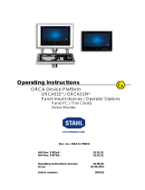
Operating Instructions
Exicom Eagle ET-3x6-Tx, ET-3x6-Fx
(valid for HW Revision 2., 5th Supplement)
R. STAHL HMI Systems GmbH
Im Gewerbegebiet Pesch 14
50767 Köln
HW-Rev. ET-3x6-Tx: 02.05.23
HW-Rev. ET-3x6-Fx: 02.05.13
Operating instructions version: 02.05.11
Issue: 29.06.2011

Table of contents Operating Instructions Exicom Eagle
Page 2 of 44 OI_Eagle_Ex_en_V_02_05_11.docx / 29.06.2011
Table of contents
Description Page
Table of contents 2
1 Preface 4
2 Device function ET-3x6-Tx, ET-3x6-Fx 4
2.1 Keyboard features 4
3 Technical details 5
4 Conformity to standards 6
5 Certifications 7
5.1 ATEX 7
5.2 DNV 7
5.3 GOST-R 7
5.4 UL INMETRO 7
5.5 CNEX 7
5.6 CKT 7
5.7 UL 8
6 Product identification 8
7 Power supply 8
7.1 Operator interfaces 8
7.2 Reader modules 8
8 Permitted maximum values 9
8.1 External, non-intrinsically safe circuits 9
8.2 External inherently safe optical interface 9
8.3 External intrinsically safe circuits 10
9 Type code 15
10 Safety Advice 16
10.1 Installation and operation 16
10.2 Special conditions 17
10.3 Installation via USB interfaces 17
10.3.1 Software installation using a USB Memory Stick 17
10.3.2 Software installation with external USB devices 17
10.4 USB interfaces 18
10.4.1 I.S. USB interfaces USB0, USB2 18
10.4.2 Ex-e USB interfaces USB1, USB3 18
10.4.2.2 Connection terminal of protection type "e" (EN 60079-7) 19
10.4.2.3 Type 3 connection version 20
11 Installation 21
11.1 ET-3x6-Tx, ET-3x6-Fx 21
12 Assembly and disassembly 22
12.1 General information 22
12.2 Cut-out ET-3x6 22
13 Operation 22
13.1 General information 22
13.2 Connections ET-3x6 23
13.2.1 Dip switch settings S3 and S4 24
13.3 Connections Ex-e terminals (X12) 25

Operating Instructions Exicom Eagle Table of contents
OI_Eagle_Ex_en_V_02_05_11.docx / 29.06.2011 Page 3 of 44
13.3.1 Labeling I.S. circuits 25
13.3.2 Connection details of the I.S. terminals 25
13.3.3 Connection details of the Ex-e terminals 25
13.3.4 Cable types and cross sections 25
14 Maintenance, service 26
14.1 Servicing 26
14.2 Data storage 26
14.3 Time function 26
15 Troubleshooting 26
16 Disposal 27
16.1.1 ROHS directive 2002/95/EC 27
16.1.2 China ROHS labeling 27
17 Front panel resistance 28
17.1 Design 28
17.2 Materials 29
17.3 Material properties 29
17.3.1 Entire device 29
17.3.2 Membrane top 30
17.3.3 Display / Touch screen 32
17.3.4 Front panel seal 32
18 UL Certification 33
18.1 General information 33
18.2 Safety Advice 33
18.2.1 Caution 33
18.3 Permitted maximum values 34
18.3.1 Electrical 34
18.4 Device with UL certification 35
18.5 Control Drawings 36
19 Accessories 39
19.1 Phoenix Contact terminal block 39
19.1.1 Data sheet Mini-Ex-terminal 39
20 Declaration of EC conformity 42
21 Release Notes 43

Preface Operating Instructions Exicom Eagle
Page 4 of 44 OI_Eagle_Ex_en_V_02_05_11.docx / 29.06.2011
1 Preface
These operating instructions are intended for the safe installation of the Eagle series operator
interfaces and cover all Ex-relevant aspects. Furthermore, these operating instructions contain
all necessary information for assembly and connection of the operator interfaces.
For the correct operation of all associated components please note, in addition to these
operating instructions, all other operating instructions enclosed in this delivery as well as
the operating instructions of the additional equipment to be connected.
Please also note that all certificates of the operator interfaces can be found in a separate
document !
2 Device function ET-3x6-Tx, ET-3x6-Fx
The ET-306 (26 cm (10.4") display), ET-316 (26 cm (10.4") display) and ET-336 (38 cm (15")
display) operator interfaces are explosion-proof equipment for installation in hazardous
environments of zone 1, 2, 21 and 22 according to ATEX guideline 94/9/EC.
The operator interfaces are intelligent visualization systems for automation applications. They
can be installed in control cabinets or panels, for example.
Users operate the device via the membrane keyboard integrated into the front plate and via the
LCD display with touch screen.
Communication with control and automation systems runs via the serial interfaces (RS-232,
RS-422/485, Ethernet) connected in the "e"-area at the back of the devices. Various peripheral
devices, such as barcode scanners, card readers, USB sticks and WLAN / Bluetooth modules
can be connected via USB interfaces or optional fitted modules.
With a wealth of functions, these operator interfaces provide optimum visualization. Their active
communication concept in combination with integrated functionality reduce the automation
system workload.
The ET-3x6-Tx and ET-3x6-Fx operator interfaces are compatible with their predecessors
(ET-8A and ET-12), both in terms of software and functionality.
2.1 Keyboard features
Pressing two keys at once (e.g. F1 + F7) is not supported by the operator interfaces !
In such a case, the system considers the key that was pressed first as "active" and
implements the associated functions and / or key bit functions !
The key pressed second is ignored.
Pressing any three of the following keys at the same time has the same effect as pressing
Ctrl + Alt + Del !
The keys are: F1, F2, F7 and F8.
ET-306 only:
The S1 – S10 softkeys can NOT be used in combination with Shift / Alt / Ctrl !
The system will only execute the original key command.

Operating Instructions Exicom Eagle Technical details
OI_Eagle_Ex_en_V_02_05_11.docx / 29.06.2011 Page 5 of 44
3 Technical details
Function / Equipment
ET-306
ET-316
ET-336
Display type
TFT Color, 64k colors
Display size
26 cm (10.4")
38 cm (15")
Resolution
VGA, 640 x 480 pixels
SVGA, 800 x 600 pixels
XGA, 1024 x 768 pixels
Display
Touch screen on glass
Touch Screen
8-wire analogue resistive
Lighting
CFL backlight
Service life of backlight at
25°C
50,000h
Brightness
350 cd/m²
250 cd/m²
(optional 600 cd/m²)
Keyboard
Polyester membrane on FR4 material; > 1 million actions
Functional keys
Freely assignable / number
Soft keys
Cursor keys
Alphanumeric keys
Numeric keys
12
Yes / 12
10
Yes
23
Yes
12
no
no
no
no
no
8
no
no
no
no
no
Real time clock / Data
buffer
Yes (capacitor buffered, maintenance-free) / > 4 days
Interfaces
Communication COM1 and
COM2
RS-232, RS-422, RS-485
Fieldbus
Profibus with 9185/12-46-10
MPI with MPI Box SSW7-RK512-RS-422
Ethernet
Alternatively Tx or Fx
Copper (Tx)
10/100BaseTx, 10/100 Mbit, increased safty (Ex-e)
Optical fiber (Fx)
100BaseFx, 100 Mbit, inherently safe (Ex op is)
Cable type optical fiber
Multimode optical fiber cable with 62.5 µm core diameter and 125 µm outer diameter
USB
2x Ex-e and 2x Ex-i
PS/2
For external I.S. keyboard (optional) or I.S. mouse (optional)
Readers (option)
Connection for: Barcode scanner, Wiegand reader, Proximity reader
Processor
LX 800, 300 MHz
Main memory [Mbyte]
Data memory [Mbyte]
256
256
Operating system
RT Target
Languages
Global, multilingual language support
Number of protocol drivers
A maximum of 4 simultaneously
Number of process images
> 1000 dynamic
Number of texts /
messages
Dynamically limited by main memory
Number of variables per
page
255
Number of messages
4096 fault messages, 4096 operation messages
Font sets
4 independent Windows unicondensed fonts
Configuration memory type
Compact flash card
Power supply
24 VDC (20.4 up to 28.8 VDC)
Connections
Via plug-in screw terminals, 2.5 mm2 green
Power consumption [A]
1.9
1.9
1.9
Housing
Stainless steel
Front plate
Aluminum with polyester membrane, touch and safety glass
Protection type
IP66 (according to EN 60529)

Conformity to standards Operating Instructions Exicom Eagle
Page 6 of 44 OI_Eagle_Ex_en_V_02_05_11.docx / 29.06.2011
Temperature range
Cold start temperature
-10…+55°C
During operation
-20…+55°C
Operating with heater *
-30…+55°C
Operating with heater *,
housing insulation and
front cover
-40...+55°C
Storage temperature
-20…+60°C
* Comment
The used heater must be construed in the way, that inside of the enclosure of the operator interface
the temperature will NOT fall below -20°C (-30°C only front plate) !
Relative humidity
90% at 40 °C, without condensation
Vibration
Operation
3 to 22Hz: 1mm
22 to 500Hz: 9.8m/s2 = 1g
Transport
3 to 9Hz: 3.5mm
9 to 500Hz: 9.8m/s2 = 1g
Shock loading
Operation
150m/s2 = ca. 15g / 11ms
Transport
250m/s2 = ca. 25g / 6ms
Dimensions [mm]
Front (w x h)
400 x 270
372 x 270
440 x 340
Cut-out (w x h)
(+/- 0.5)
385.5 x 257.5
359.5 x 257.5
427.5 x 327.5
Mounting depth
150
165
Wall thickness
8
Weight [kg]
Operator interface
11.55
11.55
14.7
Fixing frame
0.6
0.6
0.7
4 Conformity to standards
The ET-3x6-Tx and ET-3x6-Fx operator interfaces comply with the following standards and
directives:
Standard
Classification
Directive 94/9/EC
5th Supplement
EN 60079-0 : 2006
General requirements
EN 60079-1 : 2007
Flameproof enclosures "d"
EN 60079-7 : 2007
Increased safety "e"
EN 60079-11 : 2007
Intrinsic safety "i"
EN 60079-18 : 2004
Encapsulation "m"
EN 60079-28 : 2007
Optical radiation
EN 61241-0 : 2006
General requirements (dust)
EN 61241-1 : 2004
Protection by enclosures "tD" (dust)
Electromagnetic compatibility
Directive 2004/108/EC
EN 61000-6-2 (2005)
Immunity
EN 61000-6-4 (2007)
Emission

Operating Instructions Exicom Eagle Certifications
OI_Eagle_Ex_en_V_02_05_11.docx / 29.06.2011 Page 7 of 44
5 Certifications
The Eagle operator interfaces have been approved for the following scopes:
By ATEX directive 94/9/EC
for installation in zones 1, 2, 21 und 22
DNV (Det Norske Veritas)
GOST-R (Russian certification)
UL INMETRO (Brazilian certification)
CNEX (Nanyang Explosion Protected Electrical Apparatus Research Institute – Chinese
certification)
CKT (CAA JSC The National Center of Expertise and Certification Almaty Branch –
Kazakh certification)
UL (Underwriters Laboratories)
5.1 ATEX
The ATEX certification is listed below the following number:
Certificate number: TÜV 05 ATEX 7176 X
5.2 DNV
The DNV certification is listed below the following numbers:
Certificate number: A-11822
File number: 899.60
Job Id: 262.1-001689-3
5.3 GOST-R
The GOST-R certification is listed below the following number:
Certificate number: РОСС DE.ГБ04.B01280
5.4 UL INMETRO
The UL INMETRO certification is listed below the following number:
Certificate number: 06/UL-BRCR-0001X
5.5 CNEX
The CNEX certification is listed below the following number:
Certificate number: CNEx10. 1832X
5.6 CKT
The CKT certification is listed below the following numbers:
Certificate number: KCC No 1018112
KZ.0.02.0317
KZ.7500317.01.01.14106

Product identification Operating Instructions Exicom Eagle
Page 8 of 44 OI_Eagle_Ex_en_V_02_05_11.docx / 29.06.2011
5.7 UL
The UL certification is listed below the following number:
UL File Number: E202379
6 Product identification
Manufacturer
R. STAHL HMI Systems GmbH
Type code
ET-3x6-Tx / ET-3x6-Fx
CE classification:
c 0158
Testing authority and certificate
number:
TÜV 05 ATEX 7176 X
Ex-classification:
e
ATEX-directive 94/9/EC
II 2 (2) G Ex d e mb ib [ib] [op is] IIC T4
II 2 D Ex tD A21 IP65 T90°C
GOST-R
2Exdemib[ib]sIICT4X
DIP A21 TA90°C, IP65
UL INMETRO
BR-Ex d e mb ib [ib] IIC T4
CNEX
Exdembib[ib]IICT4
DIP A21 TA, T90°C
UL
Class I, Div. 2, Groups A, B, C, D
Class II, Div. 2, Groups F, G
Class III, hazardous locations
Class I, Zone 2, Group IIC
Temperature classification T4, enclosure type 1
7 Power supply
7.1 Operator interfaces
Power supply: 24.0 VDC (min. 20.4 VDC; max. 28.8 VDC)
Power consumption: max. 1.9 A
7.2 Reader modules
a) WCR1 external power supply module with intrinsically safe power supply circuit
and the following maximum values:
UO = 12.4 VDC IO = 200 mA
b) RSi1 internal intrinsically safe power supply circuit
UO = 10.4 VDC IO = 220 mA

Operating Instructions Exicom Eagle Permitted maximum values
OI_Eagle_Ex_en_V_02_05_11.docx / 29.06.2011 Page 9 of 44
8 Permitted maximum values
8.1 External, non-intrinsically safe circuits
Input voltage (X1):
Rated voltage 24 VDC (+20% / -15%)
Power consumption for Urated 1.9 A max
Max. operating voltage Um 30 VDC
RS-422/-232 COM 1 (X2):
Rated voltage RS-422: 5 VDC RS-232: ±12 VDC
Max. operating voltage Um 253 VAC
RS-422/-232 COM 2 (X3):
Rated voltage RS-422: 5 VDC RS-232: ±12 VDC
Max. operating voltage Um 253 VAC
USB-1 (X5):
Rated voltage 5 VDC
Max. operating voltage Um 253 VAC
USB-3 (X7):
Rated voltage 5 VDC
Max. operating voltage Um 253 VAC
Ethernet copper (X11):
Rated voltage 5 VDC
Rated power 100 mW
Max. operating voltage Um 30 VDC
8.2 External inherently safe optical interface
Ethernet optical fiber (X10):
Wavelength 1350 nm
Radiant power ≤ 35 mW

Permitted maximum values Operating Instructions Exicom Eagle
Page 10 of 44 OI_Eagle_Ex_en_V_02_05_11.docx / 29.06.2011
8.3 External intrinsically safe circuits
USB-0 (X4):
The maximum values for group IIC are:
Ui
=
-
V
Uo
=
5.9
V
Ii
=
-
mA
lo
=
1.02
A
Pi
=
-
mW
Po
=
6.02
W
Ci
=
0
F
Co
=
8
13
30
43
F
Li
=
0
mH
Lo
=
10
5
2
1
H
Co and Lo pairs directly above/underneath each other may be used.
The maximum values for group IIB are:
Ui
=
-
V
Uo
=
5.9
V
Ii
=
-
mA
lo
=
1.02
A
Pi
=
-
mW
Po
=
6.02
W
Ci
=
0
F
Co
=
14
26
50
89
F
Li
=
0
mH
Lo
=
0.1
0.05
0.02
0.01
mH
Co and Lo pairs directly above/underneath each other may be used.
USB-2 (X6):
The maximum values for group IIC are:
Ui
=
-
V
Uo
=
5.9
V
Ii
=
-
mA
lo
=
1.02
A
Pi
=
-
mW
Po
=
6.02
W
Ci
=
0
F
Co
=
8
13
30
43
F
Li
=
0
mH
Lo
=
10
5
2
1
H
Co and Lo pairs directly above/underneath each other may be used.
The maximum values for group IIB are:
Ui
=
-
V
Uo
=
5.9
V
Ii
=
-
mA
lo
=
1.02
A
Pi
=
-
mW
Po
=
6.02
W
Ci
=
0
F
Co
=
14
26
50
89
F
Li
=
0
mH
Lo
=
0.1
0.05
0.02
0.01
mH
Co and Lo pairs directly above/underneath each other may be used.

Operating Instructions Exicom Eagle Permitted maximum values
OI_Eagle_Ex_en_V_02_05_11.docx / 29.06.2011 Page 11 of 44
Reader (X8) +Uint 1 (power supply circuit, X8.0):
The maximum values for group IIC are:
Ui
=
-
V
Uo
=
10.4
V
Ii
=
-
mA
lo
=
220
mA
Pi
=
-
mW
Po
=
2.29
W
Ci
=
-
F
Co
=
2.41
F
Li
=
-
mH
Lo
=
0.02
mH
The maximum values for group IIB are:
Ui
=
-
V
Uo
=
10.4
V
Ii
=
-
mA
lo
=
220
mA
Pi
=
-
mW
Po
=
2.29
W
Ci
=
-
F
Co
=
12
F
Li
=
-
mH
Lo
=
50
H
Reader WCR1 (connection voltage supply, X8.1–2):
The maximum values for group IIC are:
Ui
=
12.4
V
Uo
=
-
V
Ii
=
200
mA
lo
=
-
mA
Pi
=
-
mW
Po
=
-
mW
Ci
=
0
F
Co
=
-
F
Li
=
0
mH
Lo
=
-
mH
The maximum values for group IIB are:
Ui
=
12.4
V
Uo
=
-
V
Ii
=
200
mA
lo
=
-
mA
Pi
=
-
mW
Po
=
-
mW
Ci
=
0
F
Co
=
-
F
Li
=
0
mH
Lo
=
-
mH

Permitted maximum values Operating Instructions Exicom Eagle
Page 12 of 44 OI_Eagle_Ex_en_V_02_05_11.docx / 29.06.2011
Reader WCR1 (power supply Reader, X8.3-4):
The maximum values for group IIC are:
Ui
=
-
V
Uo
=
5.88
V
Ii
=
-
mA
lo
=
200
mA
Pi
=
-
mW
Po
=
1.18
W
Ci
=
4.6
F
Co
=
28.4
F
Li
=
100
nH
Lo
=
1.9
H
The maximum values for group IIB are:
Ui
=
-
V
Uo
=
5.88
V
Ii
=
-
mA
lo
=
200
mA
Pi
=
-
mW
Po
=
1.18
W
Ci
=
4.6
F
Co
=
56.4
F
Li
=
100
nH
Lo
=
19.9
H
Reader WCR1 (signal input / output, X8.5-8):
The maximum values for group IIC are:
Ui
=
15
V
Uo
=
5.88
V
Ii
=
500
mA
lo
=
56
mA
Pi
=
2.5
W
Po
=
83
mW
Ci
=
0
F
Co
=
34
F
Li
=
0
mH
Lo
=
2
H
The maximum values for group IIB are:
Ui
=
15
V
Uo
=
5.88
V
Ii
=
500
mA
lo
=
56
mA
Pi
=
2.5
W
Po
=
83
mW
Ci
=
0
F
Co
=
63
F
Li
=
0
mH
Lo
=
20
H

Operating Instructions Exicom Eagle Permitted maximum values
OI_Eagle_Ex_en_V_02_05_11.docx / 29.06.2011 Page 13 of 44
Reader RSi1 (connection voltage supply, X8.1–2):
The maximum values for group IIC are:
Ui
=
12.4
V
Uo
=
-
V
Ii
=
220
mA
lo
=
-
mA
Pi
=
2.7
W
Po
=
-
mW
Ci
=
0
F
Co
=
-
F
Li
=
0
mH
Lo
=
-
mH
The maximum values for group IIB are:
Ui
=
12.4
V
Uo
=
-
V
Ii
=
220
mA
lo
=
-
mA
Pi
=
2.7
W
Po
=
-
mW
Ci
=
0
F
Co
=
-
F
Li
=
0
mH
Lo
=
-
mH
Reader RSi1 (power supply Reader, X8.3–4):
The maximum values for group IIC are:
Ui
=
-
V
Uo
=
5.4
V
Ii
=
-
mA
lo
=
220
mA
Pi
=
-
W
Po
=
1.19
W
Ci
=
4.2
F
Co
=
39.8
F
Li
=
100
nH
Lo
=
1.9
H
The maximum values for group IIB are:
Ui
=
-
V
Uo
=
5.4
V
Ii
=
-
mA
lo
=
220
mA
Pi
=
-
W
Po
=
1.19
W
Ci
=
4.2
F
Co
=
69.8
F
Li
=
100
nH
Lo
=
19.9
H

Permitted maximum values Operating Instructions Exicom Eagle
Page 14 of 44 OI_Eagle_Ex_en_V_02_05_11.docx / 29.06.2011
Reader RSi1 (signal input / output, X8.5-8):
The maximum values for group IIC are:
Ui
=
15
V
Uo
=
5.4
V
Ii
=
500
mA
lo
=
49
mA
Pi
=
2.5
W
Po
=
62
mW
Ci
=
0
F
Co
=
45
F
Li
=
0
mH
Lo
=
2
H
The maximum values for group IIB are:
Ui
=
15
V
Uo
=
5.4
V
Ii
=
500
mA
lo
=
49
mA
Pi
=
2.5
W
Po
=
62
mW
Ci
=
0
F
Co
=
78
F
Li
=
0
mH
Lo
=
20
mH
PS2 interface (X9):
Connection for keyboard, mouse, trackball, joystick
The maximum values for group IIC are:
Ui
=
-
V
Uo
=
5.9
V
Ii
=
-
mA
lo
=
200
mA
Pi
=
-
mW
Po
=
1.18
W
Ci
=
14
F
Co
=
19
29
F
Li
=
0
mH
Lo
=
2
1
H
Co and Lo pairs directly above/underneath each other may be used.
The maximum values for group IIB are:
Ui
=
-
V
Uo
=
5.9
V
Ii
=
-
mA
lo
=
200
mA
Pi
=
-
mW
Po
=
1.18
W
Ci
=
14
F
Co
=
13
23
46
86
F
Li
=
0
mH
Lo
=
100
50
20
10
H
Co and Lo pairs directly above/underneath each other may be used.
Please note !
- The terminal name for the keyboard as listed on the TÜV 05 ATEX 7176 X EC-type
examination certificate is wrong !
"X7" is incorrect, the correct terminal name is X9 !
Do NOT connect the optional external keyboard to live equipment !

Operating Instructions Exicom Eagle Type code
OI_Eagle_Ex_en_V_02_05_11.docx / 29.06.2011 Page 15 of 44
9 Type code
Basic device:
Exicom ET-xxx
306 / 316 / 336
Order number supplement:
Ordering code
Description
Type with
ET-3x6-Fx
Optical fiber 100 Base Fx (Ex op is) Ethernet interface
ET-3x6-Tx
Copper 10/100 Base Tx (Ex-e) Ethernet interface
ET-3x6-RSi
Plug-in module for reader with integrated decoder and
RS-232 interface
ET-3x6-WCRi
Plug-in module for reader with Wiegand interface
ET-3x6-xx-UL
Operator interface with UL certification
(May ONLY be used in ATEX areas with cable glands
instead of Conduit Hubs !) *
* See note in section "UL certification" !

Safety Advice Operating Instructions Exicom Eagle
Page 16 of 44 OI_Eagle_Ex_en_V_02_05_11.docx / 29.06.2011
10 Safety Advice
This chapter is a summary of the key safety measures. The summary is supplementary to
existing rules which staff also have to study.
The safety of persons and equipment in hazardous areas depends on compliance with all
relevant safety regulations. Thus, the installation and maintenance staff carry a particular
responsibility, requiring precise knowledge of the applicable regulations and conditions.
10.1 Installation and operation
Please note the following when installing and operating the device:
Only operator interfaces with UL certification may be installed and operated in areas
covered by the NEC (see chapter "UL certification") !
In areas covered by ATEX, this device may ONLY be installed and operated if the two
Conduit Hub connections have been replaced by conventional cable glands !
During assembly and operation of the operator interface electrostatic surface charging
must not exceed that caused by manual rubbing.
The national regulations for installation and assembly apply (e.g. EN 60079-14).
The operator interfaces may be installed in zones 1, 2, 21 or 22.
The intrinsically safe circuits must be installed according to applicable regulations.
The operator interface must only be switched on when it is closed.
When installed in zones 1, 2, 21 and 22, intrinsically safe devices suitable for zones 1, 2,
21 and 22 may be connected to the intrinsically safe power supply circuits.
The safe maximum values of the connected field device(s) must correspond to the values
listed on the data sheet or the EC type examination certificate.
Interconnecting several active devices in an intrinsically safe circuit may result in different
safe maximum values. This could compromise intrinsic safety !
After switching the operator interface off, wait for at least 1 minute before opening it.
Before opening the housing lid users must ensure that all non-intrinsically safe circuits
have been switched off. Circuits supplied from different sources may be connected !
Please note that all associated equipment (such as the SK-KJ1710, for example) must
also be switched off !
National safety and accident prevention rules.
Generally accepted technical rules.
Safety instructions contained in these operating instructions.
Any damage may compromise the explosion protection !
Use the operator interface for its intended purpose only (see "Function").
Incorrect or unauthorized use and non-compliance with the instructions in this manual will void
any warranty on our part.
No changes may be made to the operator interface or its components that compromise
explosion protection !
The operator interface may only be installed and operated in an undamaged condition !

Operating Instructions Exicom Eagle Safety Advice
OI_Eagle_Ex_en_V_02_05_11.docx / 29.06.2011 Page 17 of 44
10.2 Special conditions
The housing of the operator interface must be protected against prolonged UV radiation.
The operator interface and any connected equipment must be incorporated into the same
potential equalization system (see installation example in the Hardware Manual). An
alternative would be to connect only devices that are safely isolated from earth potential.
10.3 Installation via USB interfaces
Installation of software on the operator interfaces:
10.3.1 Software installation using a USB Memory Stick
You may only use USB memory sticks permitted for use by R. STAHL HMI Systems GmbH.
These USB memory sticks are below and in general referred to by R. STAHL HMI Systems
GmbH as "USB(i) Drives". Data may only be copied onto the operator interfaces and software
may only be installed with these USB Drives.
In hazardous areas you may only use I.S. certified USB Drives supplied by R. STAHL HMI
Systems GmbH.
In an industrial area, a permitted, non-explosion proof memory stick may be connected to
the I.S. USB interface of the operator interface after having been connected to any PC.
R. STAHL HMI Systems GmbH's USB(i) drives may also be connected to non-intrinsically
safe interfaces and can be used with the ET-3x6 series operator interfaces when
connected to such interfaces.
If devices are connected to the I.S. USB interface that have not been approved by R. STAHL
HMI Systems GmbH, protective elements may become damaged, thus compromising the
intrinsic safety of the interfaces.
In this case R. STAHL HMI Systems can no longer guarantee the intrinsic safety of the device !
10.3.2 Software installation with external USB devices
Software may be installed with the aid of any external USB devices subject to the following
conditions:
The software is installed in the safe area.
The USB devices are connected to the Ex-e USB interfaces USB1 or USB3 (X5 or X7)
with the VB-USB-INST1 connection cable.
Connection diagram with VB-USB-INST1 (hard disk, CD/DVD with power supply)

Safety Advice Operating Instructions Exicom Eagle
Page 18 of 44 OI_Eagle_Ex_en_V_02_05_11.docx / 29.06.2011
10.4 USB interfaces
The ET-3x6-Tx and ET-3x6-Fx operator interfaces have 2 USB interface channels.
Channel 1 is wired in parallel to USB0 (X4) and USB2 (X6) and can be used for the
internal (X4) or external (X6) connection of an USBi Drive.
Channel 2 is wired in parallel to USB1 (X5) and USB3 (X7) and can be used to connect an
external USB device.
The connection diagram for the ET-3x6 interfaces can be found in Chapter 13.2,
connection ET-3x6
10.4.1 I.S. USB interfaces USB0, USB2
The USB0 and USB2 I.S. USB interfaces (X4 and X6) are intended for the internal or external
connection of USBi Drives.
The maximum value for the joint power supply of USB0 and USB2 is 500 mA.
10.4.2 Ex-e USB interfaces USB1, USB3
The USB1 and USB3 Ex-e USB interfaces (X5 and X7) are intended for the connection of
external USB devices.
The maximum value for the joint power supply of USB1 and USB3 is 500 mA.
Connection variations for Ex-e USB interfaces
The two Ex-e USB interfaces have an identical structure. The X5 (USB 1) and X7 (USB 3)
terminals are for the connection of devices that can be both intrinsically safe or not intrinsically
safe.
If intrinsically safe devices are connected to the Ex-e USB interfaces of the ET-3x6
operator interfaces, R. STAHL HMI Systems GmbH can no longer guarantee the intrinsic
safety of these devices !
The following versions are possible:
1. If a USB device that is not connected to the mains is connected, voltage can be supplied
from the internal power supply (terminal 1).
2. If a USB device that is connected to the mains is connected, the internal power supply
(terminal 1) must not be connected. The power must then be supplied externally.
The interrupting capacity of the fuses of the internal USB power supplies is 1.5 kA.
The tripping characteristic of the fuses is T (time-lag, type T fuse).
The USB accessory parts are fitted inside an appropriate housing.

Operating Instructions Exicom Eagle Safety Advice
OI_Eagle_Ex_en_V_02_05_11.docx / 29.06.2011 Page 19 of 44
10.4.2.2 Connection terminal of protection type "e" (EN 60079-7)
The X5 and X7 connection terminals have protection type "e".
Flexible cables with a cross section of 0.2 – 2.5 mm² can be used.
The maximum cable length for the connection with the Ex-e USB interfaces (X5 and X7) is
2.5 m.
The insulation of the wire must reach right up to the terminal body.
10.4.2.2.1 Type 1 connection version
The USB device does not require an external power supply as it uses less than 500 mA.
No connection to the mains via other interfaces, e.g. WLAN stick.
Type 1 connection diagram (e.g. WLAN stick)
10.4.2.2.2 Type 2 connection version
The USB device does require an external power supply to function because it uses over
500 mA, e.g. hard disks, CD/DVD drives.
The USB device is connected to the mains via other interfaces, e.g. USB/serial converter,
USB-Profibus interface.
Type 2 connection diagram (e.g. hard disk, CD/DVD with power supply)

Safety Advice Operating Instructions Exicom Eagle
Page 20 of 44 OI_Eagle_Ex_en_V_02_05_11.docx / 29.06.2011
10.4.2.3 Type 3 connection version
The USB device does require an external power supply to function because it uses over
500 mA, e.g. hard disks, CD/DVD drives.
The USB device is connected to the mains via other interfaces, e.g. USB/serial converter,
USB-Profibus interface.
The USB device needs the VCC connection of the operator interface (internal supply –
terminal 1) to function.
Type 3 connection diagram (any USB device with power supply)
Page is loading ...
Page is loading ...
Page is loading ...
Page is loading ...
Page is loading ...
Page is loading ...
Page is loading ...
Page is loading ...
Page is loading ...
Page is loading ...
Page is loading ...
Page is loading ...
Page is loading ...
Page is loading ...
Page is loading ...
Page is loading ...
Page is loading ...
Page is loading ...
Page is loading ...
Page is loading ...
Page is loading ...
Page is loading ...
Page is loading ...
Page is loading ...
/