
Generic procedure & guide to completing a
Counter Loop Certificate of Test & Conformity
Overview
1. This procedure is for checking an Induction loop systems (otherwise known as
a hearing loop, T-loop or ‘AFILS’ performance when installed at a counter with
a xed loop, and can be used for systems from any manufacturer or installer.
You should always read the manufacturer’s handbooks in conjunction with this
document when testing a system.
2. The procedure takes into account how the system is actually used by the operator. A representative of the client
should be present at the time of measurement, and preferably the person who would normally set-up or enable
the system for use. You will also need access to the induction loop amplier (normally attached to the bulkhead
of the counter, or maybe available on request if it is a portable system) to conduct the tests.
3. To use this procedure the loop amplier must have an indicator which shows when the Automatic Gain Control
(AGC) is activated. This indicator may be labelled as ‘AGC’, ‘Compression’, ‘In’ or ‘Input’ on the amplier. Most
ampliers have this feature.
4. You will need to follow several steps to check the system, and write your ndings on the ‘Counter Induction Loop
Certicate of Test & Conformity’ which accompanies this document.
5. For the purposes of this document the reference standard is IEC60118-4:2014.
Equipment required
You will require:
• A eld strength meter (FSM), or professional audio analyser that reads 0dB at 400mA/m eld strength, and
headphones to listen to the loop system
• This document.
• The ‘Counter Induction Loop Certicate of Test & Conformity’ for lling in your results (shown on the right)
• Signal generator / source with adjustable output level capable driving signal
into AGC
• Cable set to connect to most input options
• Line level input - on twin (stereo) phono (RCA / pin jack) connectors.
• Line level input - on 6.3mm (1/4”) 2-pole jack connector with adapto.
• Balanced Microphone input - using XLR connector (30dB attenuation).
• Electret Microphone input on 3.5mm 2-pole jack connector (30dB attenuation).
• Bare wires – Unbalanced connection to inputs with screw terminals
Note: Depending on the output range that the signal generator is capable of achieving - cables for lower level inputs such as microphones may require in built attenuation.
Test procedure
• Use the 9 steps in the following procedure to evaluate the system,
recording data as requested as you go.
• When using the eld strength meter in Steps 3 to 8, always hold the device
(normally vertically) at the normal head height and position of the hearing
aid users. If users may be seated, take the measurement from a seated
position and hold the meter directly in front of your head.
• Measurement zones are stipulated on the ‘Counter Induction Loop
Certicate of Test & Conformity’ and represent the ear height and lateral
movement ranges of the average user as dened in the IEC 60118-4 Standard.
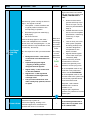
Counter Induction Loop
Certificate of Test & Conformity
For AFILS according to IEC 60118-4:2006
Designed to be used with a Field Strength Meter in conjunction with the test and commissioning procedure
Copyright © Ampetronic™ Ltd 2013.
1Signage
Is the internationally recognised induction loop sign ( ) clearly displayed?
YES
FAIL
Is the sign in an appropriate position that makes it clear where to stand to use the system?
YES
NO
Comments:
Installation details Testing details
Customer: Company:
Venue: Tester name:
Room: Date:
System Manufacturer: Test equipment manufacturer(s):
Amplier model(s): Test equipment model(s):
Comments: Customer:
2Operator
Training
Are operators at the venue / installation able to set up & operate the system?
YES
FAIL
Is there a routine maintenance and system checking schedule in place?
YES
NO
Comments:
3
Live Signal
- Equipment
Test
Does the input signal indicator show a signal is present?
YES
FAIL
Note: On the loop amplier - the input signal indicator may be labelled as ‘AGC’, ‘Compression’, ‘Input’ or ‘In’.
If no indicators are active, action is required to enable this before proceeding.
4
Live Signal
- Listening
Test
Using the Field Strength Meter & headphones - Rate each parameter
Hold the FSM upright in front of the counter 3 ear heights (1.2, 1.45 & 1.7 meters) for this test.
Background Noise i.e. the level of hum or buzz that is not intended to be heard?
Very noisy Poor Annoying: brief use only OK Very quiet
Unpleasant program signal i.e. the popping or zzing sounds alongside normal signals?
Distorted Poor Annoying: brief use only OK Very clean
Signal clarity i.e. is the sound clear, dull or mufed?
Unclear Poor Annoying: brief use only OK Very clear
Signal level i.e. is the signal at a consistent level when positioned at the counter?
Quiet & inconsistent Quiet OK & variable OK & consistent Strong & very consistent
Comments:
Answer the following questions and tick boxes as appropriate. N.B. Any tick in a red box constitutes a complete system failure.
0cm
100cm
50cm
150cm
200cm
170cm
120cm
145cm
30cm
0cm
-50cm
50cm
A
B
Oset
25cm
Distance from
counter prole
+ Oset to loop
= 55cm
C
D, E
& F
Suggested
Oset
25cm
45˚
30cm
D
E
F
A, B
& C
Counter Loop Counter
Bulkhead
Counter Loop
Counter
Bulkhead
Counter Loop
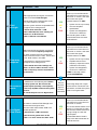
Figure 1: Side view
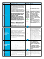
5
Magnetic
Background
Noise
A B C D E F
There any readings of > -22 dB(A) There any readings of > -32 dB(A) All reading are < -32 dB(A)
6Field
Strength
A B C D E F
Are there any readings of > -6 dB Was 0 dB not achieved All readings are 0 dB ±6 dB
Comments:
7Frequency
response
A B C D E F
100 Hz 100 Hz 100 Hz 100 Hz 100 Hz 100 Hz
1 kHz 1 kHz 1 kHz 1 kHz 1 kHz 1 kHz
5 kHz 5 kHz 5 kHz 5 kHz 5 kHz 5 kHz
3 or more zones within ±3 dB 1 kHz Less than 3 zones within ±3 dB 1 kHz Are all zones within ±3 dB 1 Khz
8Live signal -
nal check
Does the system achieve acceptable eld strength levels throughout the 6 measurement zones?
3 or more zones < -6dB All zones > -6 dB no 0 dB Are all zones > -6 dB, 0 dB achieved
Comments:
9Verdict
Based on steps 1 to 8: Does the system / facility perform according to the IEC 60118-4: 2006 Standard?
SYSTEM FAIL
(1 or more ticks in red boxes)
LIMITED PASS
(Up to 2 ticks in yellow boxes)
SYSTEM PASS
(All ticks in green/yellow boxes)
Interpretation of results:
Declaration that the system has been tested against
the requirements of IEC60118-4: 2006.
Signed: Date:
Copyright © Ampetronic™ Ltd 2013.
0cm
100cm
50cm
150cm
200cm
170cm
120cm
145cm
30cm
0cm
-50cm
50cm
A
B
Oset
25cm
Distance from
counter prole
+ Oset to loop
= 55cm
C
D, E
& F
Suggested
Oset
25cm
45˚
30cm
A, B
& C
Counter Loop Counter
Bulkhead
Counter Top
Counter
Bulkhead
Counter Loop
Figure 1: Above view
Measurement zones: Readings should be taken in 6 zones (A, B,
C, D, E & F). When taking a reading with a Field Strength Meter the
device should be held upright, to mimic the position of the telecoil
within a hearing aid.
Zones A, B & C are located at three specic heights and distances
directly in-front of the counter at the point where a user would be
expected to stand (see gure 1).
Zones D, E & F are located at 45 degrees from zones A, B & C at
the same heights. This allows for some lateral movement from the
user.
Copyright © Ampetronic™ Ltd 2013.
170cm
120cm
145cm
Page 1 of 6 Copyright © Ampetronic™ Ltd 2013-19


 1
1
 2
2
 3
3
 4
4
 5
5
 6
6


Ampetronic TFSM01 User guide
Ampetronic CLD1 Installation Handbook
Listen Technologies ILD100DC Owner's manual
Adastra LR1 Induction Loop Receiver User manual
Listen Technologies ILD122 Owner's manual
 Contacta STS-K002L-G-01 Dual Surface Mounted System User guide
