Tennant M-T20,M-M30,M-M20 Instruction Bulletin
- Type
- Instruction Bulletin

IB 9021850 (04- 2023) 1
INSTRUCTION BULLETIN
No. 9021850
Machine: M20/T20/M30
Published: 04- 2023
Rev. 00
NOTE: DO NOT DISCARD the Parts List from the Instruction Bulletin. Place the
Parts List in the appropriate place in the machine manual for future
reference. Retaining the Parts List will make it easier to reorder
individual parts and will save the cost of ordering an entire kit.
NOTE: Numbers in parenthesis ( ) are reference numbers for parts listed in Bill of Materials.
Installation instructions for kit number 9021849
Kit installation must be performed by TennantTrue
service or an authorized service provider.
SYNOPSIS:
This kit contains the parts needed to install a detergent metering kit onto:
M20 sweeper scrubbers (NA serial numbers 014001- )(CE serial numbers UO1500- ),
M30 sweeper scrubbers (NA/CE serial numbers 010001- ), and
T20 scrubbers (NA serial numbers 013001- ) (CE serial numbers UO1400- ).
Please follow step-by-step instructions.
SPECIAL TOOLS/CONSIDERATIONS: NONE
(Estimated time to complete: 3 hours)
PROTECT THE ENVIRONMENT
Please dispose of packaging materials, used machine components
such as batteries and fluids in an environmentally safe way according
to local waste disposal regulations.
Always remember to recycle.
PREPARATION: (M20/M30 ONLY)
1. Completely empty the recovery and solution
tanks, and empty/clean the hopper
(M20/M30). Refer to the Operator Manual for
instructions.
2. M20/M30 Only: Turn on the machine and
raise the hopper to the fully raised position,
turn off the machine, remove the key, and set
the parking brake.
WARNING: Lift arm pinch point. Stay
clear of hopper lift arms.
3. M20/M30 Only: Insert the safety pin into the
top support hole in the hopper lift arm.
WARNING: Raised hopper may fall.
Engage hopper support pin.
4. Remove the scrub brushes from the scrub
heads. Set the scrub brushes aside. Refer to
the Operator Manual for instructions.
5. Turn on the machine, completely lower the
scrub head, and turn off the machine.
FOR SAFETY: Before leaving or servicing
machine, stop on level surface, turn off
machine, set parking brake, and remove key.
6. Open the front shroud.
7. Disconnect the battery cables from the
battery.
WARNING: Always disconnect battery
cables from machine before working on
electrical components.
8. Remove the battery from the machine. Set
the battery aside.
FOR SAFETY: When servicing machine, avoid
contact with battery acid.

IB 9021850 (04- 2023)2
INSTALLATION: (ALL MACHINES)
FRONT
23
Replace plug with
switch (23)
Panel
assembly
Flat bar
Battery flap
Operator
station
FIG. 1 - All Machines
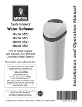
NOTE:If necessary, remove the panel assembly
from the operator station to install the rocker
switch (23) into the panel assembly.
1. Remove the plug from the panel assembly.
Discard the plug. (Fig. 1)
2. Insert the rocker switch (23) into the panel
assembly. (Fig. 1)
3. Connect the main wire harness to the rocker
switch (23). (Fig. 1/Fig. 7/Fig. 8)
4. Reinstall the panel assembly, battery flap, and
flat bar onto the operator station. (Fig. 1)
5. Reinstall the battery into the battery
compartment. Do Not reconnect the battery
cables to the battery. Battery cables are
reconnected after kit installation is complete.
INSTALLATION: (M20/T20)
NOTE:If installing kit onto M30 sweeper
scrubber, proceed to INSTALLATION: (M30).
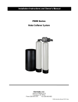
1. Cut a 12 in. (305 mm) length from the 0.38 in.
dia. PVC hose (5). (Fig. 2)
2. Assemble the 12 in. (305 mm) 0.38 in. dia.
PVC hose (5) cut in the previous step and
parts/components into the detergent tank (1).
(Fig. 2)

IB 9021850 (04- 2023) 3
19
3
47
18
5
20
6
19
1
2
4
5
21
To: Detergent
pump (8) IN
Mounting
bracket
Solution tank
FRONT
(40 in.
(1016 mm))
(12 in.
(305mm))
FIG. 2 - M20/T20 ONLY
3. Install the detergent tank (1)/detergent tank
bracket (18) onto the solution tank. (Fig. 2)
4. Insert the rubber grommet (21) into the
mounting bracket. (Fig. 2)
5. Cut a 40 in. (1016 mm) length from the
0.38 in. dia. PVC hose (5). (Fig. 2)
6. Insert the elbow fitting (4) into the 12 in.
(305 mm) 0.38 in. dia. PVC hose (5) and
connect the 40 in. (1016 mm) 0.38 in. dia.
PVC hose (5) to the elbow fitting. (Fig. 2)
7. Route the 40 in. (1016 mm) 0.38 in. dia. PVC
hose (5) through the rubber grommet (21) in
the mounting bracket and down to the scrub
head. (Fig. 2)

IB 9021850 (04- 2023)4
FRONT
Install valve
mounting
bracket (22)
FIG. 3 - M20/T20 ONLY
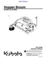
8. Install the valve mounting bracket (22) onto
the frame of the machine. (Fig. 3/Fig. 4)
9. Install the detergent pump (8) onto the valve
mounting bracket (22). (Fig. 4)
10.Disconnect the hose from the solution filter
located inside the solution tank and remove
the plastic elbow connector from the solution
filter. (Fig. 4)
11.Install the plastic elbow fitting (17) into the
solution filter and then install fittings (14), (13),
(16), and (12) onto the elbow fitting. (Fig. 4)
12.Connect the hose from the solution pump IN
port to the plastic straight fitting (16) installed
in the previous step. (Fig. 4)
13.Route the 40 in. (1016 mm) 0.38 in. dia. PVC
hose (5) from the detergent tank (1) to the
detergent pump (8) and connect the hose to
the detergent pump IN port. (Fig. 4)
14.Cut another 40 in. (1016 mm) length from the
0.38 in. dia. PVC hose (5). (Fig. 2)
15.Connect the 40 in. (1016 mm) 0.38 in. dia.
PVC hose (5) to the elbow fitting (12)
connected to the t- fitting (13). (Fig. 4)
16.Route the 40 in. (1016 mm) 0.38 in. dia. PVC
hose (5) to the detergent pump (8) and
connect the hose to the OUT port. (Fig. 4)
17.Use cable ties to secure the newly installed
PVC hoses (5) away from moving parts so the
hoses cannot be damaged due to rubbing or
getting caught in the moving parts.
18.Connect the main wire harness to the
detergent pump (8). (Fig. 4/Fig. 7/Fig. 8)
19.Proceed to TEST MACHINE (ALL
MACHINES)

IB 9021850 (04- 2023) 5
FRONT
5
17
22
11
12 13
10
16
7
7
14
19
20
8
Solution
pump IN
port
Solution
tank
Solution
filter
5
From: Detergent
tank
14
7
IN
OUT
(40 in.
(1016 mm))
If necessary, use
39 in. (991 mm)
0.62 in. dia. PVC
hose (25) to
replace existing
PVC hose
FIG. 4 - M20/T20 ONLY

IB 9021850 (04- 2023)6
INSTALLATION: (M30)
FRONT
1
2
3
4
5
6
7
8
9
10
11
12
13
14
4
7
5
7
15
Solution filter
(located inside
solution tank)
Bulkhead plastic
fitting (located
undersolutiontank)
Plastic elbow fitting
(located under
solution tank)
Solution
pump IN port
IN
OUT
5
16
(12 in.
(305 mm))
(40 in.
(1016 mm))
(12 in. (305 mm))
Scrub
head
Machine frame
If necessary, use 39 in.
(991 mm) 0.62 in. dia.
PVC hose (25) to replace
existing PVC hose
FIG. 5 - M30 ONLY
1. Cut a 12 in. (305 mm) length from the 0.38 in.
dia. PVC hose (5). (Fig. 5)
2. Assemble the 12 in. (305 mm) 0.38 in. dia.
PVC hose (5) cut in the previous step and
parts/components into the detergent tank (1).
(Fig. 5)
3. Install the detergent tank (1) onto the solution
tank. (Fig. 5)
4. Insert the rubber grommet (21) into the
mounting bracket. (Fig. 5)

IB 9021850 (04- 2023) 7
5. Cut a 40 in. (1016 mm) length from the 0.38
in. dia. PVC hose (5). (Fig. 5)
6. Insert the elbow fitting (4) into the 12 in.
(305 mm) 0.38 in. dia. PVC hose (5) and
connect the 40 in. (1016 mm) 0.38 in. dia.
PVC hose (5) to the elbow fitting. (Fig. 5)
7. Route the 40 in. (1016 mm) 0.38 in. dia. PVC
hose (5) through the rubber grommet (21) in
the mounting bracket and down to the scrub
head. (Fig. 5)
8. Install the housing plate (9) onto the frame of
the machine. (Fig. 5/Fig. 6)
9. Install the detergent pump (8) onto the
housing plate (9). (Fig. 6)
10.Disconnect the hose from the solution filter
located inside the solution tank. (Fig. 5)
11. Install the fittings (14), (13), (16), and (12)
onto the plastic elbow fitting located under the
solution tank. (Fig. 5)
12.Connect the hose from the solution pump IN
port to the plastic straight fitting (16) installed
in the previous step. (Fig. 5)
13.Cut another 12 in. (356 mm) from the 0.38 in.
dia. PVC hose (5).
14.Connect the 12 in. (356 mm) 0.38 in. dia. PVC
hose (5) to the elbow fitting (12) connected to
the t- fitting (13). (Fig. 6)
15.Route the 12 in. (356 mm) 0.38 in. dia. PVC
hose (5) to the detergent pump (8) and
connect the hose to the OUT port. (Fig. 6)
16.Use cable ties to secure the newly installed
PVC hoses (5) away from moving parts so the
hoses cannot be damaged due to rubbing or
getting caught in the moving parts.
17.Connect the main wire harness to the
detergent pump (8). (Fig. 5/Fig. 7/Fig. 8)
18.Proceed to TEST MACHINE (ALL
MACHINES)
FRONT
Install housing
plate (9)
FIG. 6 - M30 ONLY

IB 9021850 (04- 2023)8
TEST MACHINE: (ALL MACHINES)
1. Reconnect the battery cables to the battery.
2. M20/M30 Only: Turn on the machine, remove
the hopper support pin, and lower the hopper.
Refer to the Operator Manual for additional
instructions and safety information.
WARNING: Lift arm pinch point. Stay
clear of hopper lift arms.
3. Raise the scrub head and turn off the
machine.
4. Reinstall the brushes into the scrub head.
Refer to the Operator Manual for instructions.
5. Fill the solution tank with cool clean water.
Refer to the Operator Manual for instructions.
6. Fill the detergent tank (1) with detergent and
install the tank cap (2) onto the detergent
tank.
7. Start and test the machine. Operate the
machine over a short distance and press the
detergent metering switch to dispense
solution. Observe newly installed parts to
ensure there are no leaks around hoses/
fittings. Repair leaks. If the detergent metering
is not functioning, troubleshoot the detergent
metering electrical circuit. Repair electrical
issues as necessary.

IB 9021850 (04- 2023) 9
FIG. 7

IB 9021850 (04- 2023)10
FIG. 8

IB 9021850 (04- 2023) 11
Bill Of Materials For Metering Kit, Detgt, DI - 9021849
Ref.
Tennant
Part No. Description Qty.
11022229 Tank, Detgt, Trimmed (All) 1
2 1011885 Cap, Tank (All) 1
3 20952 Screen, Pump (All) 1
4 20951 Fitting, Plstc, E90, Bm06/Bm06 (All) 2
5 C080172 Hose, PVC, Clr, 0.38id, 0.56od, Bulk (8.0 ft) (All) 1
620944 Grommet, Pye, 0.37id, F/1.5h, .13 Matl (All) 1
7 43844 Clamp, Hose, Wormdrive, 0.25- 0.62d, .31w (All) 4
8 73260 Pump, Detgt, 14vdc, 150ml/Min 20PSI (All) 1
9 1033792 Plate, Hsng [Fast] (M30) 1
10 24265 Screw, Pan, Phl, M4 X 0.70 X 16, SS (All) 2
11 01683 Washer, Flat, 10, SS (All) 3
12 79484 Fitting, Plstc, E90, Bm06/Pm12, Nyl (All) 1
13 42133A Fitting, Plstc, Tee, Pf12/Pf12/Pf12 (All) 1
14 24544 Fitting, Plstc, Str, Pm12/Pm12 1.60l (All) 1
15 76099 Screw, Hex, M8 X 1.25 X 25, Fmg (All) 1
16 365095 Fitting, Plstc, Str, Bm10/Pm12 (M20/T20) 1
17 69785 Fitting, Plstc, E90, Pf12/Pm12 (M20/T20) 1
18 1025159 Bracket, Mtg, Detgt And Spray Wand (M20/T20) 1
19 09740 Screw, Hex, M8 X 1.25 X 20, SS (M20/T20) 6
20 1017218 Washer, Flat, 0.32b 1.00d .12, SS (M20/T20) 6
21 10632- 2 Grommet, Rbr, 0.62id, F/0.9h, .12 Matl (M20/T20) 1
22 1021325 Bracket, Mtg, Valve (M20/T20) 1
23 1255914 Switch, Rocker [MOM, Off, MOM, Dual LED] (All) 1
24 54333 Clamp, Hose, Worm Drive, 0.31- 0.88d, .31w (All) 2
25 C460117 Hose, PVC, Brd, 0.62id, 0.96od, Bulk (3.3 ft) (All) 1
Tennant Company
10400 Clean Street
Eden Prairie, Mn 55344- 2650
-
 1
1
-
 2
2
-
 3
3
-
 4
4
-
 5
5
-
 6
6
-
 7
7
-
 8
8
-
 9
9
-
 10
10
-
 11
11


Tennant M-T20,M-M30,M-M20 Instruction Bulletin
- Type
- Instruction Bulletin
Ask a question and I''ll find the answer in the document
Finding information in a document is now easier with AI
Related papers
Other documents
-
IPC Eagle Boxer User manual
-
 NPK GH30 User manual
-
Smithco Spray Star 1000 Owner's manual
-
 Morton M340012 Installation guide
-
Fendt 1149MT Workshop Service Manual
-
Sharp FD44450X16 Installation guide
-
 First Sales PDIM150-HE Installation Instructions And Owner's Manual
-
Grundfos UNILIFT AP35B Installation And Operating Instructions Manual
-
 Land Pride HB series User manual
-
XtremeVAC DCL800TM '12-'15 User manual


