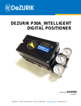
DeZurik POSITIONER PMV (P36C/P41C) Operating instructions

Type
Operating instructions

DeZurik POSITIONER PMV (P36C/P41C)

This device provides precise control for demanding process requirements. By using force balance principle, it converts a signal pressure into proportional air pressure to control pneumatic actuators.

The positioner has a modular design for easy parts replacement, and its housing uses an adjustable O-ring seal.

Some of the key features include:

  • P36C model: Accepts a 3-15psi, 3-9psi, or 9-15 psi input signal
  • P41C model: Accepts either a 0-20mA or a 4-20mA input signal
  • Ingress Protection: IP 65/NEMA 4
  • Maximum supply pressure: 1 MPa 145 psi
DeZURIK, Inc. Sartell, Minnesota USA | Phone: 320-259-2000 | www.dezurik.com | info@dezurik.com
PMV P36C AND P41C
POSITIONERS
USED WITH DEZURIK PNEUMATIC ACTUATORS
Instruction
D10327
August 2012
DeZURIK
Instruction and Operating Manual Page 2 © 2022 DeZURIK, Inc.
Instructions
These instructions are for use by personnel who are responsible for the installation, operation and
maintenance of DeZURIK valves, actuators or accessories.
Safety Messages
All safety messages in the instructions are identified by a general warning sign and the signal word CAUTION,
WARNING or DANGER. These messages indicate procedures to avoid injury or death.
Safety label(s) on the product indicate hazards that can cause injury or death. If a safety label becomes difficult
to see or read, or if a label has been removed, please contact DeZURIK for replacement label(s).
Personnel involved in the installation or maintenance of valves should be constantly alert to potential
emission of pipeline material and take appropriate safety precautions. Always wear suitable protection
when dealing with hazardous pipeline materials. Handle valves which have been removed from service
with suitable protection for any potential pipeline material in the valve.
Inspection
Your DeZURIK product has been packaged to provide protection during shipment; however, items can be
damaged in transport. Carefully inspect the unit for damage upon arrival and file a claim with the carrier if
damage is apparent.
Parts
Replaceable wear parts are listed on the assembly drawing. These parts can be stocked to minimize
downtime. Order parts from your local DeZURIK sales representative or directly from DeZURIK. When ordering
parts please provide the following information:
If the valve has a data plate: please include the 7-digit part number with either 4-digit revision number
(example: 9999999R000) or 8-digit serial number (example: S1900001) whichever is applicable. The
data plate will be attached to the valve assembly. Also, include the part name, the assembly drawing
number, the balloon number and the quantity stated on the assembly drawing.
If there isn't any data plate visible on the valve: please include valve model number, part name, and
item number from the assembly drawing. You may contact your local DeZURIK Representative to help
you identify your valve.
DeZURIK Service
DeZURIK service personnel are available to maintain and repair all DeZURIK products. DeZURIK also offers
customized training programs and consultation services. For more information, contact your local DeZURIK
sales representative or visit our website at DeZURIK.com.
DeZURIK
August 2012 Page 3 D10327
Table of Contents
Technical Specifications - - - - - - - - - - - - - - - - - - - - - - - - - - - - - - - - - - - - - - - - - - - -
4
Description - - - - - - - - - - - - - - - - - - - - - - - - - - - - - - - - - - - - - - - - - - - - - - - - - - - - - -
5
Operation - - - - - - - - - - - - - - - - - - - - - - - - - - - - - - - - - - - - - - - - - - - - - - - - - - - - - - -
5
Cam Selection - - - - - - - - - - - - - - - - - - - - - - - - - - - - - - - - - - - - - - - - - - - - - - - - - - -
6
Installation
Air Requirements - - - - - - - - - - - - - - - - - - - - - - - - - - - - - - - - - - - - - - - - - - - - - - -
Air Connections - - - - - - - - - - - - - - - - - - - - - - - - - - - - - - - - - - - - - - - - - - - - - - - -
I/P Unit Electrical Connections - - - - - - - - - - - - - - - - - - - - - - - - - - - - - - - - - - - - - -
Front Cover and Indicator Cover - - - - - - - - - - - - - - - - - - - - - - - - - - - - - - - - - - - - -
6
6
7
7
Reversing the Positioner Action - - - - - - - - - - - - - - - - - - - - - - - - - - - - - - - - - - - - - - -
8
Cam Adjustment - - - - - - - - - - - - - - - - - - - - - - - - - - - - - - - - - - - - - - - - - - - - - - - - - -
9
Zero and Span Adjustment
Span Adjustment - - - - - - - - - - - - - - - - - - - - - - - - - - - - - - - - - - - - - - - - - - - - - - -
Zero Adjustment - - - - - - - - - - - - - - - - - - - - - - - - - - - - - - - - - - - - - - - - - - - - - - -
9
9
Resetting the Range Spring - - - - - - - - - - - - - - - - - - - - - - - - - - - - - - - - - - - - - - - - - -
10
Indicator Adjustment - - - - - - - - - - - - - - - - - - - - - - - - - - - - - - - - - - - - - - - - - - - - - - -
Adjusting Travel Speed Dampers - - - - - - - - - - - - - - - - - - - - - - - - - - - - - - - - - - - -
10
10
I/P Electric Control Unit, P41C
The I/P Unit - - - - - - - - - - - - - - - - - - - - - - - - - - - - - - - - - - - - - - - - - - - - - - - - - - -
Filter - - - - - - - - - - - - - - - - - - - - - - - - - - - - - - - - - - - - - - - - - - - - - - - - - - - - - - - -
11
11
Installing I/P Unit On Positioner - - - - - - - - - - - - - - - - - - - - - - - - - - - - - - - - - - - - - - -
12
Maintenance for Positioners
Pilot Valve - - - - - - - - - - - - - - - - - - - - - - - - - - - - - - - - - - - - - - - - - - - - - - - - - - - -
Diaphragm - - - - - - - - - - - - - - - - - - - - - - - - - - - - - - - - - - - - - - - - - - - - - - - - - - - -
Feedback Spring - - - - - - - - - - - - - - - - - - - - - - - - - - - - - - - - - - - - - - - - - - - - - - - -
Balance Arm - - - - - - - - - - - - - - - - - - - - - - - - - - - - - - - - - - - - - - - - - - - - - - - - - - -
Lower Arm - - - - - - - - - - - - - - - - - - - - - - - - - - - - - - - - - - - - - - - - - - - - - - - - - - - -
O-Ring - - - - - - - - - - - - - - - - - - - - - - - - - - - - - - - - - - - - - - - - - - - - - - - - - - - - - - -
14
14
15
15
Troubleshooting - - - - - - - - - - - - - - - - - - - - - - - - - - - - - - - - - - - - - - - - - - - - - - - - - -
17
Parts - - - - - - - - - - - - - - - - - - - - - - - - - - - - - - - - - - - - - - - - - - - - - - - - - - - - - - - - - -
19
DeZURIK
D10327 Page 4 August 2012
Technical Specifications
Model P36C
Both Models
Model P41C
Input signal
20100 kPa 315 psi
420mA
Linearity
=<0,5% a
=<0,75% a
Hysterisis
=<0,75% a
=<1%
Repeatability
=<0,5% a
=<0,5% a
Gain factor at 80%
load. (Supply: 87 psi)
1000 (kPa/kPa)
1000 (psi/psi)
Gain factor at 50%
load. (Supply: 87 psi)
1250 (kPa/kPa)
1250 (psi/psi)
Air consumption at
supply pressure:
±20%
±20%
0,2 MPa/29 psi
5,4 nl/min 0.19 SCFM
6,1 nl/min 0.22 SCFM
0,4 MPa/58 psi
12,3 nl/min 0.43 SCFM
13,6 nl/min 0.48 SCFM
0,6 MPa/87 psi
20 nl/min 0.71S CFM
22 nl/min 0.78 SCFM
0,8 MPa/116 psi
27,8 nl/min 0.98 SCFM
30,5 nl/min 1.08 SCFM
1 MPa/145 psi
35,7 nl/min 1.26 SCFM
39 nl/min 1.38 SCFM
Air delivery at
Supply pressure:
±20%
0,2 MPa/29 psi
135 nl/min 4.7 SCFM
0,4 MPa/58 psi
250 nl/min 8.7 SCFM
0,6 MPa/87 psi
360 nl/min 12.6 SCFM
0,8 MPa/116 psi
480 nl/min 16.8 SCFM
1 MPa/145 psi
590 nl/min 20.6 SCFM
Supply Pressure
Max 1 MPa 145 psi
0,151 MPa 8145 psi
Temperature Range
-15°C to +85°C
(5°F to 185°F)
Connector threads
1/4" NTP or G
Gauge threads
1/8" NTP or G
Weight std.
1,1 kg 2.4 lbs
1,6kg 3.5 lbs
Weight with gauges
1,3 kg 2.9 lbs
1,8 kg 4 lbs
Ingress Protection
IP 65/NEMA 4
DeZURIK
August 2012 Page 5 D10327
Description
The positioner is a precision instrument which, when used in conjunction with a DeZURIK actuator, can
provide the exacting control necessary to satisfy the most demanding process requirements.
The model P36C will accept a 3-15psi, 3-9psi, or 9-15 psi input signal.
The model P41C will accept either a 0-20mA or a 4-20mA input signal.
The modular design allows for easy parts replacement, and quick access to Zero and Span
adjustments. The housing uses an O-ring seal that can be adjusted to a sealed or drained position.
Operation
P36C and P41C positioners operate on a force balance principal. Force is applied from a signal
pressure that is transmitted through a diaphragm (1) to the balance arm (2). The feedback spring (3)
provides the opposing force. This force is proportional to the level of the lower arm (4). The lower arm
level is determined by the position of the cam (5), which is secured to the spindle (6). The spindle is
connected to the actuator shaft thus providing the feedback from the actuator and valve. See Figure 1.
When the opposing forces are equal, the balance arm (2) and the spool in the pilot valve (7) are in
neutral position and the complete system is in a balanced condition.
Figure 1 Internal Parts
Air is supplied through port S to the pilot valve, which controls air flow through ports C1 and C2.
Starting from a balanced condition, an increased control pressure will deflect the diaphragm (1) down,
compressing the feedback spring (3). The balance arm (2) moves the spool (7) in the pilot valve (8)
thus supplying air to the actuator. At the same time air is exhausted from the actuator and vented to
atmosphere through the pilot valve and the OUT port.
Air pressure to the actuator is increased, causing the actuator to move the valve and the positioner
spindle (6). The spindle and cam (5) rotate, forcing the lower arm upward, compressing the feedback
spring (3). This motion continues until the two forces are equal and the system returns to a balanced
condition.
DeZURIK
D10327 Page 6 August 2012
Cam Selection
Each cam is designed to provide split range instrument signals. Standard cam characterization is linear;
however, other characterizations are available.
Installation
Positioners installed in hazardous areas can be ignition sources. Ensure positioners used in
hazardous areas have proper fire/explosion ratings.
Air Requirements
Maximum positioner supply pressure is 145 psi (1 MPa).
Supply air must be clean, dry and free from oil, water, moisture, dirt and debris. The air should be
freeze-dried or similar to a dew point of at least 18 degrees F (10°C) below lowest ambient
temperature.
A 30 micron (or finer) filter/regulator should be installed as close to the positioner as possible to ensure
proper supply air quality.
Air Connections
Air connections are for 1/4" NPT male connectors and are marked on the positioner. Gauge ports are
for 1/8" NPT.
DeZURIK recommends Loctite® 577 tape or similar for sealing.
Port I
Input instrument pneumatic signal 3-15 psi (20-100kPa)
Port S
Supply air, maximum 145 psi (1 MPa), minimum 21 psi
(0.15 MPa) for P41C
Port C1, C2
Actuator connections. C2 opening port
OUTLET
Exhaust air port. Do not plug.
Port Ip
Gauge port for pneumatic input signal (P36C).
Port IE
Input electric signal (420 mA) (P41C)
Port P
Gauge port for I/P unit output pressure (P41C)
Figure 2 - Connecting Block
DeZURIK
August 2012 Page 7 D10327
Installation (Continued)
The outlet port is used for venting the positioner. All air from the positioner, actuator and I/P unit is
vented to atmosphere through this port. Do not plug this port. A high flow silencer or an exhaust pipe
can be connected to the outlet port to prevent foreign objects from entering and blocking the exhaust.
When using gas for supply, please contact. Port I should be plugged on the P41C. For single acting
operation, plug port C1 for increasing signal to OPEN, or C2 for increasing signal to CLOSE.
Note: See Figure 4 for proper cam position.
With the I/P unit mounted, the positioner is supplied with air from port S and does not need an external
air supply. See pages 811 for more information on the I/P unit.
I/P Unit Electrical Connections
Electrical connection on I/P unit accepts 1/2" NPT or PG 13,5 cable gland.
See Figure 10E for wiring connections. Maximum recommended wire size is 16 AWG.
Front Cover and Indicator Cover
The front cover is secured to the pneumatic positioner with four captive screws and sealed with an O-
ring (1). This sealing system allows for complete sealing or draining of the positioner by changing the
position of the O-ring. The O-ring system is common to the Pneumatic positioner, I/P unit and
Feedback unit in the Valve Control System.
The O-ring can be looped over notches (2) in the front cover to allow for drainage. There are eight
locations on the front cover where the O-ring can be looped. See Figure 3.
Figure 3 Front Cover and Indicator Cover
The indicator cover (3) is O-ring sealed and secured by a bayonet coupling. The indicator cover is also
used to secure the identification cover (4).
To remove the indicator cover turn it slightly counterclockwise until it loosens. Once loosened, the
identification cover and O-ring (5) can be removed. When installing the indicator cover and identification
cover ensure the O-ring is properly sealed.
DeZURIK
D10327 Page 8 August 2012
Reversing the Positioner Action
To change the positioner action from increasing signal to OPEN to increasing signal to CLOSE, or vice
versa, follow the steps below.
Moving parts from accidental operation of power actuator can cause personal injury or
equipment damage. Disconnect and lock out power to the actuator before servicing.
1. Shut off the supply air pressure and the input signal pressure.
2. On double-acting cylinders, disconnect and reverse the two connections to positioner ports C1
and C2. For spring-return cylinders, proceed to step 3.
3. Remove the positioner cover and dial indicator.
4. Loosen the cam locking nut screw and remove the cam locking nut.
5. Turn the cam over and position the cam so the cam roller is about 1/32" from the stop on the
cam. See Figure 4.
Figure 4 Cam Positions
6. Tighten the locking screw allow room for movement of the cam as the cam locking nut is
tightened.
7. Turn on the supply and input pressures and operate the valve.
8. Adjust the zero and span adjustments, if necessary.
DeZURIK
August 2012 Page 9 D10327
Cam Adjustment
Figure 5 Cam Adjustment
1. With the cover and indicator removed, loosen the screw (1) and turn the cam locking nut (2)
counterclockwise until the cam loosens. See Figure 5.
2. Adjust the cam (3) as desired, making sure the ball bearing (4) is always riding on an active lobe
on the cam.
3. Finger tighten the locking nut and tighten the screw (1).
Note: Ensure screw (1) is loose from the cam before tightening locking nut (2).
4. Install and adjust the indicator, and install cover.
Zero and Span Adjustment
Span Adjustment
Span is adjusted with the yellow (upper) thumb wheel (1)
located on the feedback spring. See Figure 6. To adjust
the span, loosen the locking screw (2) and turn the yellow
thumb wheel. Do not allow the top of the spring to contact
the spring guide (3). When span is set, tighten the locking
screw. Always check Zero after adjusting Span.
Zero Adjustment
Zero is adjusted by turning the silver (lower) thumb wheel
(4) located on the lower arm (5). It can also be adjusted
externally with a screwdriver (7), through the zero adjust
opening. Remember to re-install the zero adjust cover (6)
to keep the unit clean.
Figure 6 Zero and Span Adjustment
DeZURIK
D10327 Page 10 August 2012
Resetting the Range Spring
If the correct span cannot be obtained after 2 or 3 zero/span adjustments, reset the range spring as
follows:
1. Disconnect air supply and remove the range spring from the positioner.
2. Loosen screws (1 and 2).
3. Adjust the collar so it is 3/16" or 9/32"* below the flange face.
*Depending on spring stylesee Figure 7
Figure 7 Spring Styles
4. Adjust the spring end to 1/32" clearance.
5. Tighten screws (1 and 2).
6. Adjust the lower zero screw so that 1 or 3 threads are showing (depending on spring style).
7. Reinstall the range spring assembly.
Indicator Adjustment
To adjust the indicator, remove front cover and pull the
indicator upward until it comes off the Allen screw. Before
installing the indicator make sure the Allen screw is
tightened. Press the indicator on the screw and adjust it
by rotating clockwise into position.
Adjusting Travel Speed Dampers
The dampers (5) located on the connecting block provide
a simple means of adjusting the actuator travel speed.
See Figure 8.
For double acting actuators, set the damper marked
Supply to fully open and adjust only the damper marked
Outlet.
For single acting actuators, adjust both the Supply and
Outlet dampers for operation.
Figure 8 Speed Dampers
DeZURIK
August 2012 Page 11 D10327
I/P Electric Control Unit, P41C
The I/P Unit
The I/P unit is mounted directly on top of the positioner. Span and Zero for the I/P converter are factory
set. No external air supply is needed, as the I/P unit is supplied with air from the positioner. The I/P unit
accepts a 420 mA input signal. (Other ranges are available on request.)
Positioners installed in hazardous areas can be ignition sources. Ensure positioners used in
hazardous areas have proper fire/explosion ratings.
Filter
The filter plug can blow out and cause injury or damage if it is removed while under pressure.
Do not remove the filter plug when the positioner is pressurized.
The I/P unit is equipped with a built in filter. The threaded filter plug can easily be removed for
replacement. During replacement, always check the filter compartment, and clean if necessary. Make
sure the filter plug O-ring is in good condition.
DeZURIK
D10327 Page 12 August 2012
Installing I/P Unit On Positioner
Positioners installed in hazardous areas can be ignition sources. Ensure positioners used in
hazardous areas have proper fire/explosion ratings.
1. Turn off the supply air and remove the connecting block (1), gauge or plug from port IP, and the
existing gasket (4) between the positioner (2) and connecting block. See Figure 9.
2. Carefully install the new gasket supplied with the I/P unit.
Figure 9 Installing I/P Electric Control Unit P41C
3. Ensure the relief valve spring (5) is installed properly.
4. Install the connecting block on the Positioner, and plug port I.
5. Remove cover on I/P unit.
DeZURIK
August 2012 Page 13 D10327
Installing I/P Unit On Positioner (Continued)
6. Install the I/P unit on the top of the positioner, making sure the four O-rings are in the correct
places. See Figure 10b.
7. Tighten the I/P unit with the three screws. See Figure 10a.
Figure 10 I/P Unit On Positioner
8. Connect input signal cable to port lE and tighten the cable gland (see Figure 10e).
9. Adjust the O-ring on the I/P unit housing to desired position; sealed or drained (see Figure 10c).
10. Install a plug or a gauge in port P, and make sure the filter plug is tightened (see Figure 10d).
DeZURIK
D10327 Page 14 August 2012
Maintenance for Positioners
Pilot Valve
To remove the pilot valve for cleaning:
1. Remove the screw (1) and carefully lift out the
complete assembly (2).
2. Gently remove the spool (3) from the block.
3. Clean the parts, using methylate cleaner or
similar.
4. Blow the parts dry with compressed air.
Note: If the parts show signs of wear, replace
the assembly. Do not mix parts from other
assemblies.
5. Check the O-rings, then secure and install the
pilot valve assembly to the positioner and
secure it with the screw (1).
6. Ensure the leaf spring (4) on the balance arm (5) is properly fitted in the groove on the spool (6).
7. Check again to ensure smooth operation of the assembly.
Diaphragm
On P41C positioners the I/P unit must be removed
to reach the diaphragm. See Figure 12.
1. Loosen screws (1), remove the diaphragm
cover (2).
2. Loosen screw (3), then remove diaphragm
(4) and washers (5).
3. When installing the diaphragm, place one
washer on each side of the diaphragm.
Ensure the raised circle on the washers is
facing the diaphragm.
4. Install the screw (3) and tighten.
5. Check the O-ring on the diaphragm cover
(2), then install and secure the cover with
screws (1).
Figure 11 Location of Pilot Valve Spool
Figure 12 Diaphragm Removal and
Installation
DeZURIK
August 2012 Page 15 D10327
Maintenance for Positioners (Continued)
Feedback Spring
Once the front cover and indicator are removed, the feedback spring can be easily reached. See Figure
13.
1. Hold the spring (1) from the top, pull down and
out.
2. When installing, hold the assembly at the top,
guide the lower part to position on the zero
screw, then press down until it fits easily under
the balance arm (2).
3. Ensure the assembly is aligned properly against
the balance arm.
Balance Arm
The balance arm can only be removed after I/P unit, diaphragm and feedback spring have been
removed. See Figure 14.
Refer to "Diaphragm" and "Feedback" sections above.
1. Loosen the screws (3) and remove the balance
arm.
2. When installing the balance arm make sure the
leafspring (4) on the underside of the balance
arm (5) is properly engaged in the groove (6) of
the spool in the pilot valve.
3. Tighten the two screws (3) holding the balance
arm to the positioner.
Figure 13 Feedback Spring Access
Figure 14 Balance Arm Access
DeZURIK
D10327 Page 16 August 2012
Maintenance for Positioners (Continued)
Lower Arm
After the front cover has been removed, the lower arm can be easily reached. See Figure 15.
Figure 15 Lower Arm
1. Remove the indicator, feedback spring and the cam.
2. Loosen screw (2) and remove twist stop (1).
3. Remove screw (3), lower arm (4), rod (5) and spring (6).
4. Check rod and lower arm for wear, and replace if necessary.
5. Clean the rod and install it in the lower arm.
Note: The lower arm should move easily and smoothly.
6. Install the lower arm and rod assembly into the positioner housing, making sure the spring (6) is
attached properly to the lower arm and positioner housing.
7. Secure the lower arm and rod assembly with the screw (3).
8. Check again that the lower arm moves smoothly.
9. Apply a small amount of grease on the small tongue on the lower arm, then install and secure
the twist stop.
10. Install the cam, feedback spring, indicator and front cover.
O-Rings
With time and use, O-rings can become brittle. This can cause poor operation or failure. Always check
O-rings when performing work on the positioner, and replace any brittle O-rings.
Note: A thin layer of silicon grease applied on the O-rings prolongs their life.
DeZURIK
August 2012 Page 17 D10327
Troubleshooting
Condition
Possible Cause
Corrective Action
Signal change has no effect on
actuator position.
Indicator is loose.
Check indicator and screw.
Re-position indicator and
tighten.
Air supply is not adequate.
Check air supply to positioner,
and tubing to actuator.
Input signal is fluctuating.
Check input signal. Repair or
replace wiring.
Diaphragm is damaged.
Check diaphragm for damage or
leakage. Repair or replace
diaphragm.
Pilot valve is dirty or worn.
Check pilot valve function. Clean
or replace pilot valve.
Cam is incorrectly positioned.
Check cam for correct setting.
Signal change results in actuator
running to end position
Positioner is loose.
Check coupling between
positioner and actuator.
Cam is loose.
Check cam position and locking
screw.
Input signal is fluctuating.
Check input signal. Repair or
replace wiring.
Inaccurate Positioning
Pilot valve is dirty or worn.
Check pilot valve function. Clean
or replace pilot valve.
Diaphragm is damaged.
Check diaphragm; repair or
replace diaphragm.
Input signal is fluctuating.
Check input signal. Repair or
replace wiring.
Actuator is not sized correctly.
Check sizing. Replace with
correct actuator.
Valve torque is increased from
wear or damage.
Rebuild or replace valve.
DeZURIK
D10327 Page 18 August 2012
Figure 16 Positioner Configurations
DeZURIK
August 2012 Page 19 D10327
Parts
Table A: Parts - Positioner
Part No.
Qty
Description
1
1
Housing
2
1
Front cover with O-ring
3
1
Connecting block a
4
1
Relief valve spring
6
1
Gasket P5 a
7
1
Diaphragm cover with O-ring
8
1
Diaphragm
9
2
Diaphragm washer
10
1
Balance arm
13
1
Feedback spring b
18
1
Lower arm assembly
19
1
Rod
20
1
Spring
21
1
Indicator: arrow, flag, or
pointer
22
1
Indicator Cover c
24
1
Twist stop
25
1
Pilot valve with O-rings
26
1
Shaft with O-rings and screw
27
1
Cam locking nut
29
1
Zero cover
30
1
Cover
32
11
Ball bearing
35
1
Identification cover
a. Specify 1/4" NTP or G.
b. Specify 315 psi or 630 psi Spring Assembly.
c. Specify Flag, Transparent or Opaque.
Table A: Parts Positioner, continued
Part No.
Qty
Description
36
4
Plug a
37
1
Cam
3845
1
Screw set
4653
1
O-ring set
54
1
Spindle adaptor
a. Specify 1/8” NTP or G.
Table B: Parts I/P Unit
Part No.
Qty
Description
61
1
I/P box
62
1
I/P cover with screws
63
1
I/P nose assembly a
64
1
Relief valve spring
65
1
Filter and plug
66
1
Filter (5 nos)
67
1
I/P Gasket
70
1
O-ring
71
1
I/P converter
73
1
Round I/P mounting
bracket with hardware
74
1
I/P enclosure with
converter b
a. Specify 1/4" NTP or G.
b. Specify Std., Cenelec (flameproof), or
Explosion Proof FM.
Limited Warranty
DeZURIK, Inc. (“Seller”) manufactured products, auxiliaries and parts thereof that we manufacture for a period of twenty-four (24) months from date
of shipment from Seller’s factory, are warranted to the original purchaser only against defective workmanship and material, but only if properly stored,
installed, operated, and serviced in accordance with Seller’s recommendations and instructions.
For items proven to be defective within the warranty period, your exclusive remedy under this limited warranty is repair or replacement of the defective
item, at Seller’s option, FCA Incoterms 2020 Seller’s facility with removal, transportation, and installation at your cost.
Products or parts manufactured by others but furnished by Seller are not covered by this limited warranty. Seller may provide repair or replacement
for other’s products or parts only to the extent provided in and honored by the original manufacturers warranty to Seller, in each case subject to the
limitations contained in the original manufacturer’s warranty.
No claim for transportation, labor, or special or consequential damages or any other loss, cost or damage is being provided in this limited warranty.
You shall be solely responsible for determining suitability for use and in no event shall Seller be liable in this respect.
This limited warranty does not warrant that any Seller product or part is resistant to corrosion, erosion, abrasion or other sources of failure, nor does
Seller warrant a minimum length of service.
Your failure to give written notice to us of any alleged defect under this warranty within twenty (20) days of its discovery, or attempts by someone other
than Seller or its authorized representatives to remedy the alleged defects therein, or failure to return product or parts for repair or replacement as
herein provided, or failure to store, install, or operate said products and parts according to the recommendations and instructions furnished by Seller
shall be a waiver by you of all rights under this limited warranty.
This limited warranty is voided by any misuse, modification, abuse or alteration of Seller’s product or part, accident, fire, flood or other Act of God, or
your failure to pay entire contract price when due.
The foregoing limited warranty shall be null and void if, after shipment from our factory, the item is modified in any way or a component of another
manufacturer, such as but not limited to; an actuator is attached to the item by anyone other than a Seller factory authorized service personnel.
All orders accepted shall be deemed accepted subject to this limited warranty, which shall be exclusive of any other or previous warranty, and this
shall be the only effective guarantee or warranty binding on Seller, despite anything to the contrary contained in the purchase order or represented by
any agent or employee of Seller in writing or otherwise, notwithstanding, including but not limited to implied warranties.
THE FOREGOING REPAIR AND REPLACEMENT LIMITED WARRANTY IS IN LIEU OF ALL OTHER WARRANTIES, OBLIGATIONS AND
LIABILITIES, INCLUDING, BUT NOT LIMITED TO, ALL WARRANTIES OF FITNESS FOR A PARTICULAR PURPOSE OR OF MERCHANTABILITY
OR OTHERWISE, EXPRESSED OR IMPLIED IN FACT OR BY LAW, AND STATE SELLER’S ENTIRE AND EXCLUSIVE LIABILITY AND YOUR
EXCLUSIVE REMEDY FOR ANY CLAIM IN CONNECTION WITH THE SALE AND FURNISHING OF SERVICES, GOODS OR PARTS, THEIR
DESIGN, SUITABILITY FOR USE, INSTALLATION OR OPERATIONS. NEITHER ANY PERFORMANCE OR OTHER CONDUCT, NOR ANY ORAL
OR WRITTEN INFORMATION, STATEMENT, OR ADVICE PREPARED BY SELLER OR ANY OF OUR EMPLOYEES OR AGENTS WILL CREATE A
WARRANTY, OR IN ANY WAY INCREASE THE SCOPE OR DURATION OF THE LIMITED WARRANTY.
Disclaimer
Metric fasteners should not be used with ASME Class 150/300 bolt holes and flange bolt patterns. If you use metric fasteners with ASME Class 150/300
bolt holes and flange bolt patterns, it may lead to product failure, injury, and loss of life. DeZURIK Inc. disclaims all liability associated with the use of
metric fasteners with ASME Class 150/300 bolt holes and flange patterns, including but not limited to personal injury, loss of life, loss of product,
production time, equipment, property damage, lost profits, consequential damages of any kind and environment damage and/or cleanup. Use of metric
fasteners with ASME Class 150/300 bolt holes and flange bolt patterns is a misuse that voids all warranties and contractual assurances. If you use
metric fasteners with ASME Class 150/300 bolt holes and flange bolt patterns, you do so at your sole risk and any liability associated with such use shall
not be the responsibility of DeZURIK, Inc. In addition to the foregoing, DeZURIK’s Manufacturer’s Conditions apply.
Limitation of Liability
IN NO EVENT SHALL SELLER BE LIABLE FOR ANY DIRECT, INDIRECT, SPECIAL, PUNITIVE, EXEMPLARY, OR CONSEQUENTIAL DAMAGES
(INCLUDING, BUT NOT LIMITED TO; DAMAGE TO OR LOSS OF OTHER PROPERTY OR EQUIPMENT, BUSINESS INTERUPTION, COST OF
SUBSTITUTE PRODUCTS, LOSS OF TIME, LOSS OF PROFITS OR REVENUE, COST OF CAPTIAL, LOSS OF USE, OR DIMINUTION IN VALUE)
WHATSOEVER, AND SELLER’S LIABILITY, UNDER NO CIRCUMSTANCES, WILL EXCEED THE CONTRACT PRICE FOR THE GOODS AND/OR
SERVICES FOR WHICH LIABILITY IS CLAIMED. ANY ACTION FOR BREACH OF CONTRACT BY YOU, OTHER THAN RIGHTS RESPECTING OUR
LIMITED WARRANTY DESCRIBED ABOVE, MUST BE COMMENCED WITHIN 12 MONTHS AFTER THE DATE OF SALE.
Sales and Service
For information about our worldwide locations, approvals, certifications and local representative:
Web site: www.dezurik.com E-Mail: info@dezurik.com
250 Riverside Ave. N., Sartell, MN 56377 ● Phone: 320-259-2000 ● Fax: 320-259-2227
DeZURIK, Inc. reserves the right to incorporate our latest design and material changes without notice or obligation.
Design features, materials of construction and dimensional data, as described in this manual, are provided for your information only
and should not be relied upon unless confirmed in writing by DeZURIK, Inc. Certified drawings are available upon request.
December 2022
  • Page 1 1
  • Page 2 2
  • Page 3 3
  • Page 4 4
  • Page 5 5
  • Page 6 6
  • Page 7 7
  • Page 8 8
  • Page 9 9
  • Page 10 10
  • Page 11 11
  • Page 12 12
  • Page 13 13
  • Page 14 14
  • Page 15 15
  • Page 16 16
  • Page 17 17
  • Page 18 18
  • Page 19 19
  • Page 20 20

DeZurik POSITIONER PMV (P36C/P41C) Operating instructions

Type
Operating instructions

DeZurik POSITIONER PMV (P36C/P41C)

This device provides precise control for demanding process requirements. By using force balance principle, it converts a signal pressure into proportional air pressure to control pneumatic actuators.

The positioner has a modular design for easy parts replacement, and its housing uses an adjustable O-ring seal.

Some of the key features include:

  • P36C model: Accepts a 3-15psi, 3-9psi, or 9-15 psi input signal
  • P41C model: Accepts either a 0-20mA or a 4-20mA input signal
  • Ingress Protection: IP 65/NEMA 4
  • Maximum supply pressure: 1 MPa 145 psi

Ask a question and I''ll find the answer in the document

Finding information in a document is now easier with AI