Mackie DRM 18S User manual
- Category
- Supplementary music equipment
- Type
- User manual
This manual is also suitable for

OWNER’S MANUAL
2000W 18" Professional Powered Subwoofer
DRM18S

DRM18S 2000W 18" Professional Powered Subwoofer
2
DRM18S 2000W 18” Professional Powered Subwoofer
Important Safety Instructions
1. Read these instructions.
2. Keep these instructions.
3. Heed all warnings.
4. Follow all instructions.
5. Do not use this apparatus near water.
6. Clean only with a dry cloth.
7. Do not block any ventilation openings. Install in accordance
with the manufacturer’s instructions.
8. Minimum distance (5 cm) around the apparatus for sucient ventilation.
The ventilation should not be impeded by covering the ventilation openings
with items, such as newspapers, table-cloths, curtains, etc.
9. Do not install near any heat sources such as radiators, heat registers,
stoves, or other apparatus (including amplifiers) that produce heat.
10. No naked flame sources, such as lighted candles, should be placed
on the apparatus.
11. Do not defeat the safety purpose of the polarized or grounding-type plug.
A polarized plug has two blades with one wider than the other. A grounding-type
plug has two blades and a third grounding prong. The wide blade or the third
prong are provided for your safety. If the provided plug does not fit into your
outlet, consult an electrician for replacement of the obsolete outlet.
12. Protect the power cord from being walked on or pinched particularly at plugs,
convenience receptacles, and the point where they exit from the apparatus.
13. Only use attachments/accessories specified by the manufacturer.
14. Use only with a cart, stand, tripod, bracket, or table
specified by the manufacturer, or sold with the apparatus.
When a cart is used, use caution when moving the cart/
apparatus combination to avoid injury from tip-over.
15. Unplug this apparatus during lightning storms or when
unused for long periods of time.
16. Refer all servicing to qualified service personnel. Servicing
is required when the apparatus has been damaged in any
way, such as power-supply cord or plug is damaged, liquid has been spilled or
objects have fallen into the apparatus, the apparatus has been exposed to rain
or moisture, does not operate normally, or has been dropped.
17. This apparatus shall not be exposed to dripping or splashing, and no object filled
with liquids, such as vases or beer glasses, shall be placed on the apparatus.
18. Do not overload wall outlets and extension cords as this can result in a risk
of fire or electric shock.
PORTABLE CART
WARNING
CAUTION
The lightning flash with arrowhead symbol within an equilateral
triangle is intended to alert the user to the prescence of uninsulated
“dangerous voltage” within the product’s enclosure, that may be of
significant magnitude to constitute a risk of electric shock to persons.
RISK OF ELECTRIC SHOCK! DO NOT OPEN!
CAUTION: TO REDUCE THE RISK OF ELECTRIC SHOCK DO NOT
REMOVE COVER (OR BACK). NO USER-SERVICEABLE PARTS INSIDE.
REFER SERVICING TO QUALIFIED PERSONNEL.
The exclamation point within an equilateral triangle is intended
to alert the user of the prescence of important operating and
maintaining (servicing) instructions in the literature accompanying
the appliance.
WARNING — To reduce the risk of fire or electric shock, do not
expose this apparatus to rain or moisture.
CAUTION — To prevent electric shock hazard, do not connect
to mains power supply while grille is removed.
Laite on liitettävä suojakoskettimilla varustettuun pistorasiaan.
Apparatet må tilkoples jordet stikkontakt.
Apparaten skall anslutas till jordat uttag.
19. This apparatus has been designed with Class-I construction and
must be connected to a mains socket outlet with a protective earthing
connection (the third grounding prong).
20. This apparatus has been equipped with a rocker-style AC mains power
switch. This switch is located on the rear panel and should remain readily
accessible to the user.
21. The MAINS plug or an appliance coupler is used as the disconnect device,
so the disconnect device shall remain readily operable.
22. The use of apparatus is in tropical and/or moderate climates.
23. NOTE: This equipment has been tested and found to comply with the limits
for a Class A digital device, pursuant to part 5 of the FCC Rules. These
limits are designed to provide reasonable protection against harmful
interference when the equipment is operated in a commercial environment.
This equipment generates, uses, and can radiate radio frequency energy
and, if not installed and used in accordance with the instruction manual,
may cause harmful interference to radio communications. Operation
of this equipment in a residential area is likely to cause harmful interference
in which case the user will be required to correct the interference at his
own expense.
WARNING: Operation of DRM8S in a residential environment could cause
radio interference.
CAUTION: Changes or modifications to this device not expressly approved
by LOUD Audio, LLC could void the user’s authority to operate the equipment
under FCC rules.
24. This apparatus does not exceed the Class A/Class B (whichever
is applicable) limits for radio noise emissions from digital apparatus
as set out in the radio interference regulations of the Canadian Department
of Communications.
ATTENTION
— Le présent appareil numérique n’émet pas de bruits
radioélectriques dépassant las limites applicables aux appareils
numériques de class A/de class B (selon le cas) prescrites dans
le réglement sur le brouillage radioélectrique édicté par les ministere
des communications du Canada.
25. Exposure to extremely high noise levels may cause permanent hearing loss.
Individuals vary considerably in susceptibility to noise-induced hearing loss,
but nearly everyone will lose some hearing if exposed to suciently intense
noise for a period of time. The U.S. Government’s Occupational Safety and
Health Administration (OSHA) has specified the permissible noise level
exposures shown in the following chart.
According to OSHA, any exposure in excess of these permissible limits
could result in some hearing loss. To ensure against potentially dangerous
exposure to high sound pressure levels, it is recommended that all persons
exposed to equipment capable of producing high sound pressure levels
use hearing protectors while the equipment is in operation. Ear plugs or
protectors in the ear canals or over the ears must be worn when operating
the equipment in order to prevent permanent hearing loss if exposure is in
excess of the limits set forth here:
Duration, per
day in hours
Sound Level dBA,
Slow Response
Typical Example
8 90 Duo in small club
6 92
4 95 Subway Train
3 97
2 00 Very loud classical music
.5 02
05 Matt screaming at Troy about deadlines
0.5 0
0.25 or less 5 Loudest parts at a rock concert
Correct disposal of this product: This symbol indicates that this product should not be disposed of with your household waste, according to the WEEE directive (202/9/EU)
and your national law. This product should be handed over to an authorized collection site for recycling waste electrical and electronic equipment (EEE). Improper handling of this type of waste
could have a possible negative impact on the environment and human health due to potentially hazardous substances that are generally associated with EEE. At the same time, your cooperation
in the correct disposal of this product will contribute to the eective usage of natural resources. For more information about where you can drop o your waste equipment for recycling, please
contact your local city oce, waste authority, or your household waste disposal service.

Owner’s Manual
3
Owner’s Manual
Contents Features
Part No. SW274 Rev. B 06/9
©2019 LOUD Audio, LLC. All Rights Reserved.
• High-eciency 2000W Class-D amplifier oers ample
headroom for professional applications
o Universal power supply (00-240 VAC) with Power Factor
Correction technology ensures consistent performance
even with unstable AC power
o Next-gen protection circuitry keeps transducers safe
and ensures peak performance in all applications
• Advanced Impulse™ DSP module
o Precision acoustic correction delivers reference quality
sound that is consistent even at high SPL
• DRM Control Dashboard™ features a high-resolution full
color display for easy single-knob access to configuration,
processing, and more
o View current crossover setting, high-resolution metering,
and more from a single overview window
o User adjustable variable crossover point allows
for matching to any speaker system plus a DRM specific
mode tailors DRM8S for full-range DRM loudspeakers
o Save and recall up to 6 user presets for various
applications and venues
o Cardioid mode allows for easy setup of a directional
subwoofer array
o Screensaver plus dimmer and contrast control
o Polarity Invert
o Alignment Delay control for delay stacks
o System lock with 4-digit passcode
• Dual independent input channels with Full-Range Direct
and High-Pass outputs
• Premium components
o Road-worthy 8mm plywood construction and internal
bracing oers optimal acoustic performance with
a touring-grade textured coating and powder-coated
heavy gauge steel grille
o 8" high-excursion woofer oers increased bass response,
low distortion, and professional reliability to withstand
the most demanding applications
• Acoustic design with no compromises
o DRM8S is acoustically designed with ample internal
volume and precision tuned ports to naturally deliver
the bass you need with minimal distortion
• Versatile configuration options
o Flyable via optional FB00 Fly Bar and FKDRM8S
Flyware Kit
o M20 threaded pole attachment for use with DRM Series
loudspeakers and other pole mountable speakers
• Max SPL: 35 dB
• 90 lb / 40.8 kg
Like us
Follow us
Watch our dang videos
Important Safety Instructions ........................................... 2
Contents / Features ............................................................ 3
Introduction / Getting Started ........................................... 4
Hookup Diagrams ............................................................... 5
DRM8S Subwoofer: Rear Panel Features ......................0
1. Power Connection ...................................................0
2. Power Switch ..........................................................0
3. XLR and 1/4” Combo Inputs ...................................0
4. Direct Out ................................................................
5. High-Pass Out .........................................................
6. LCD Display ............................................................
7. Speaker Control Knob ............................................
DRM Control Dashboard™ ................................................2
Main ............................................................................. 2
Subwoofer Mode ........................................................3
X-Over ..........................................................................3
Cardio ..........................................................................4
Delay ............................................................................ 4
Configuration .............................................................. 5
Protection Circuitry ........................................................... 7
Limiting .......................................................................7
Overexcursion Protection .......................................... 7
Thermal Protection ....................................................7
AC Power ............................................................................8
Care and Maintenance ......................................................8
Placement ..........................................................................8
Rigging ..............................................................................8
A Note About Cardioid Operation ....................................20
Appendix A: Service Information ...................................... 2
Appendix B: Technical Information ................................. 22
DRM8S Frequency Graph ........................................23
DRM8S Dimensions .................................................23
DRM8S Block Diagram ............................................ 24
Limited Warranty .............................................................. 25

DRM18S 2000W 18" Professional Powered Subwoofer
4
DRM18S 2000W 18” Professional Powered Subwoofer
Getting Started
Introduction
The DRM8S 2000W 8” Professional Powered Subwoofer
delivers class-leading power via an ultra-ecient Class-D
amplifier with next-gen protection and Power Factor
Correction technology provides peak low-end performance
when you need it.
Advanced Impulse™ DSP provides acoustic correction
via precision tuned FIR filters for accurate, punchy sound
typically experienced only with massive touring systems.
The DRM Control Dashboard™ features a high-contrast,
full-color display for quick access metering, crossover
settings, and more.
Designed to match the rest of the DRM Series perfectly,
the DRM8S is stackable, flyable, and is equipped with
a pole cup for maximum versatility.
How to Use This Manual:
Afer this introduction, a getting started guide will help
you get things set up fast. The hookup diagrams show
some typical DRM8S subwoofer setups.
This icon marks information that is critically
important or unique! For your own good, read and
remember them...it is a good idea to pay special
attention to these areas in the Owner’s Manual
marked with the “VERY IMPORTANT” hand icon.
There’s an illustration of a microscope,
so, of course, you’re going to get more
detailed information when you see this little
guy. There are explanations of features
and practical tips listed here.
It’s a good idea to pay attention to text displayed
next to a note icon, as this icon draws attention
to certain features and functions relating to the
usage of the DRM8S.
The following steps will help you set up the DRM8S quickly.
. Make all initial connections with the power switches OFF
on all equipment. Make sure the master volume, level and gain
controls are all the way down.
2. Connect the outputs from the mixing console (or other
signal source) to the inputs on the DRM8S, then connect
the high pass outputs from the subwoofer to the inputs
of the loudspeakers.
3. Push the line cord securely into the subwoofer’s /
loudspeaker’s IEC connectors and plug the other ends into
grounded AC outlets. The subwoofer/loudspeaker may accept
the appropriate voltage as indicated near the IEC connector.
4. Turn the mixer (or other signal source) on.
5. Turn the subwoofer on.
6. Turn the loudspeakers on.
7. Make sure the subwoofer’s channel levels are set
to (or near) 0 dB.
8. Make sure the loudspeaker’s channel levels are set
to (or near) 0 dB.
9. Start the signal source and raise the mixer’s main L/R
fader up to a comfortably loud listening level.
Things to Remember:
• Never listen to loud music for prolonged periods. Please see
the Safety Instructions on page 2 for information on hearing
protection.
• As a general guide, the mixer (or other signal source) should
be turned on first, DRM8S subwoofer next, and loudspeakers
last. As such, the loudspeakers should also be turned o first,
followed by the DRM8S, then the mixer. This will reduce
the possibility of any turn-on or turn-o thumps and other
noises generated by any upstream equipment from coming
out of the speakers.
• Save the shipping boxes and packing materials! You may
need them someday. Besides, the cats will love playing
in them and jumping out at you unexpectedly. Remember
to pretend like you are surprised!
• Save your sales receipt in a safe place.
Please write the serial numbers here for future reference
(i.e., insurance claims, tech support, return authorization,
make dad proud, etc.)
Purchased at:
Date of purchase:

Owner’s Manual
5
Owner’s Manual
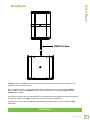
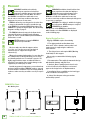
Hookup Diagrams
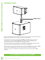
A DRM8S subwoofer and DRM loudspeaker is the perfect tool for a standard PA setup, whether installed in a club,
gymnasium, house of worship and more.
Here you will want to connect a cable from the mixer’s lef main output jack to the ch. input jack of the DRM8S.
The ch. high-pass output of the DRM8S subwoofer is then connected to the ch. input of the DRM loudspeaker
[DRM22 in this example].
It is possible to reproduce this exact same hookup in stereo. Simply utilize the lef and right main outputs from the mixer
to feed the ch. input of each DRM8S and mirror the rest of the system as described above.
You will want to set the crossover to DRM Top as described in detail on page 3. Or set it to Var if using a non-DRM
loudspeaker.
Simple PA Setup
SPM400 Pole Mount

DRM18S 2000W 18" Professional Powered Subwoofer
6
DRM18S 2000W 18” Professional Powered Subwoofer
Pole-mounted DRM2A arrayable loudspeaker with single DRM8S
Hookup Diagrams continued...
This type of setup will typically be found at small indoor or outdoor gigs, festivals, weddings, or parades where a high output
PA with wide coverage and throw is necessary. This is a great setup for local DIY bands, too.
The lef output from a mixer feeds the ch. input of a Mackie DRM8S powered subwoofer. The ch. direct output
of the subwoofer feeds the input of a Mackie DRM2A powered arrayable loudspeaker. The DRM2A reproduces
the mid-to-high frequencies in mono, and the sub provides the low frequencies in mono.
It is possible to reproduce this exact same hookup in stereo. Simply utilize the lef and right main outputs from the mixer
to feed the ch. inputs of each subwoofer and mirror the rest of the system as identified above.
Another important aspect to keep in mind is the rigging setup. In this diagram, the DRM2As are pole-mounted on a DRM8S
subwoofer, utilizing an SPM400 adjustable pole. Refer to pages 8 and 9 for more information about rigging.
You will want to set the crossover to DRM Top as described in detail on page 3. Or set it to Var if using a non-DRM
loudspeaker.
SPM400 Pole Mount

Owner’s Manual
7
Owner’s Manual
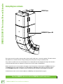
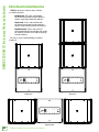
Three ground-stacked DRM2A arrayable loudspeakers with single DRM8S
Hookup Diagrams continued...
This is the perfect setup for any venue where the audience is level with and sloping upward from the stage and PA.
For example, a bowl, a shed or a gym with bleachers.
The lef output from a mixer feeds the ch. input of a single Mackie DRM8S powered subwoofer. The ch. high-pass output
of the subwoofer feeds the input of a Mackie DRM2A powered arrayable loudspeaker. The output of that Mackie DRM2A
powered arrayable loudspeaker feeds the input of the next Mackie DRM2A powered arrayable loudspeaker. The DRM2As
reproduce the mid-to-high frequencies in mono, and the sub provides the low frequencies in mono.
It is possible to reproduce this exact same hookup in stereo. Simply utilize the lef and right main outputs from the mixer
to feed the ch. input of each DRM8S and mirror the rest of the system as described above.
Another important aspect to keep in mind is the rigging setup. In this diagram, the DRM2As are ground stacked
on a DRM8S utilizing the FKDRM18S Flyware Kit. This system may also be flown utilizing the FB00 Flybar,
with the DRM8S powered subwoofer on top. See pages 8-9 for more information about rigging.
You will want to set the crossover to DRM Top as described in detail on page 3. Or set it to Var if using a non-DRM
loudspeaker.
FKDRM18S Flyware Kit

DRM18S 2000W 18" Professional Powered Subwoofer
8
DRM18S 2000W 18” Professional Powered Subwoofer
Hookup Diagrams continued...
Two flown DRM8S subwoofers with four DRM2A arrayable loudspeakers
This setup is perfect for installs, touring systems, festivals and/or small stages...any venue requiring a 75–00 foot throw.
Two subwoofers are introduced to this setup, providing even low frequency coverage for the flown subs.
It is possible to reproduce this exact same hookup in stereo. Simply utilize the lef and right main outputs from the mixer
to feed the main inputs of the top subwoofers to mirror the rest of the system as identified here.
Another important aspect to keep in mind is the rigging setup of loudspeakers. In this diagram, the DRM8S subwoofers
and DRM2A powered arrayable loudspeakers are flown utilizing an FB00 Flybar. Note that each subwoofer requires
its own FKDRM18S Flyware Kit, as well. Refer to pages 8 and 9 for more information about rigging (and eyebolts).
You will want to set the crossover on both subwoofers to DRM Top as described in detail on page 3.
FKDRM18S Flyware Kit
FB100 Flybar

Owner’s Manual
9
Owner’s Manual
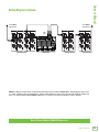
Daisy-Chaining Multiple DRM18S Subwoofers
Hookup Diagrams continued...
DRM8S subwoofers may be daisy-chained via the male XLR connector labeled “DIRECT OUT”. Simply plug the signal source
(i.e., mixer output) into the ch. input jack(s), and patch that subwoofer’s direct out jack to the next subwoofer’s input jack,
and so on, daisy-chaining multiple DRM8S subwoofers. See above for visual representations of daisy-chaining.
INPUT
DIRECT OUT
INPUT
DIRECT OUT
HIGH-PASS OUT HIGH-PASS OUT
INPUT
DIRECT OUT
INPUT
DIRECT OUT
HIGH-PASS OUT HIGH-PASS OUT
INPUT
DIRECT OUT
INPUT
DIRECT OUT
HIGH-PASS OUT HIGH-PASS OUT
INPUT
DIRECT OUT
INPUT
DIRECT OUT
HIGH-PASS OUT HIGH-PASS OUT
1402VLZ4 Mixer
To next DRM18S
subwoofer input
To next DRM18S
subwoofer input
Main
Outs

DRM18S 2000W 18" Professional Powered Subwoofer
10
DRM18S 2000W 18” Professional Powered Subwoofer
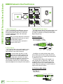
DRM18S Subwoofer: Rear Panel Features
. Power Connection
This is a standard 3-prong IEC power connector.
Connect the detachable power cord (included in
the packaging with the subwoofer) to the power
receptacle, and plug the other end of the power
cord into an AC outlet.
Make sure that the AC power is matched to
the AC power indicated on the rear panel
(below the IEC receptacle).
Disconnecting the plug’s ground pin is
dangerous. Don’t do it!
2. Power Switch
Press the top of this rocker switch inwards to turn
on the subwoofer. Press the bottom of this rocker
switch inwards to turn o the subwoofer.
As a general guide, the mixer (or other
signal source) should be turned on first,
subwoofers next, and loudspeakers last.
As such, the loudspeakers should also be turned
o first, followed by the subwoofers, then the mixer.
This will reduce the possibility of any turn-on or
turn-o thumps and other noises generated by any
upstream equipment from coming out of the speakers.
3. XLR and /4" Combo Inputs
The input channels may accept a balanced mic signal
using an XLR connector. They are wired as follows,
according to standards specified by the AES (Audio
Engineering Society).
XLR Balanced Wiring:
Pin = Shield (ground)
Pin 2 = Positive (+ or hot)
Pin 3 = Negative (– or cold)
In addition to accepting a balanced mic signal
using an XLR connector, these input channels may
also accept /4" line-level signals driven by balanced
or unbalanced sources.
To connect balanced lines to these inputs, use
a /4" Tip-Ring-Sleeve (TRS) plug. “TRS” stands
for Tip-Ring-Sleeve, the three connection points
available on a stereo /4" or balanced phone jack
or plug. TRS jacks and plugs are used for balanced
signals and are wired as follows:
/4" TRS Balanced Mono Wiring:
Sleeve = Shield
Tip = Hot (+)
Ring = Cold (–)
2
3
1
SHIELD
COLD
HOT
SHIELD
COLD
HOT
3
2
1
SLEEVE
TIPSLEEVE
TIP
RING
RING
TIP
SLEEVERING
PUSH FOR SETTINGS
50-60 Hz 110W
100-240VAC
SPEAKER CONTROL
INPUT
DIRECT OUT
INPUT
DIRECT OUT
HIGH-PASS OUT HIGH-PASS OUT
5
1
2
467
3

Owner’s Manual
11
Owner’s Manual
DRM8S Subwoofer: Rear Panel Features continued...
To connect unbalanced lines to these inputs,
use a /4" mono (TS) phone plug, wired as follows:
/4" TS Unbalanced Mono Wiring:
Sleeve = Shield
Tip = Hot (+)
NEVER connect the output of an amplifier
directly to a DRM’s input jack. This could
damage the input circuitry!
4. Direct Out
This is a male XLR-type connector that produces
exactly the same signal that is connected to the input
jack located above it. Use it to daisy-chain several DRM
subwoofers together o the same signal source(s).
They are wired as follows, according to standards
specified by the AES (Audio Engineering Society):
Balanced XLR Output Connector
Pin – Shield (ground)
Pin 2 – Positive (+ or hot)
Pin 3 – Negative (– or cold)
See page 9 to learn more about daisy-chaining
DRM8S subwoofers.
SLEEVE
TIP
TIPSLEEVE
TIP
SLEEVE
2
1
SHIELD
COLD
HOT
3
SHIELD
COLD
HOT
3
2
1
5. High-Pass Out
Typically, full-range loudspeakers are connected
to the high pass outputs to “split” the work with
the DRM8S subwoofer. The subwoofer handles all
of the low frequencies and the loudspeakers handle
the rest. As a result, it is more ecient and a bit louder.
Balanced XLR male connectors are provided
for the line-level Ch. and 2 high pass outputs.
The subwoofer’s crossover splits the input signals
into two frequency bands. The low frequency range
below 90 Hz goes to the internal amplifier that powers
the subwoofer. The frequency range above 90 Hz
is sent to these line-level output jacks.
The level control and polarity setting have no eect
on the high pass outputs. The outputs are separate
and maintain the stereo separation of the input signals.
It is wired the same as the direct outputs as seen
to the lef.
6. LCD Display
This modern, high-resolution, all-color TFT LCD
Display is one of the most vital features of the DRM18S
subwoofer. It displays subwoofer information including
(but not limited to) levels, subwoofer mode, crossover,
cardioid mode, delay setting, lock / unlock status and
other parameters.
The brightness is controllable, but
an overall screen brightness is required
for certain aspects of the set-up options.
7. Speaker Control Knob
This push-button rotary encoder allows you to access
functions such as master level control and metering,
polarity / inversion setting, crossover, setup functions,
product information and much more!
PUSH FOR SETTINGS
SPEAKER CONTROL
1 2
Non-Inverted
+3
Subwoofer Mode :
Crossover :
DRM Top
Cardioid Mode :
Front-Facing
Delay :
33 ms
67

DRM18S 2000W 18" Professional Powered Subwoofer
12
DRM18S 2000W 18” Professional Powered Subwoofer
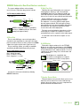
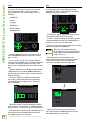
DRM Control Dashboard™
The following list provides the high level navigation
items, in order, on the user interface and their
subsequent user controlled parameters.
The default screen is the main view, as seen below:
Main – This displays the I/O metering,
subwoofer mode, crossover, cardio and delay
settings and more. The only thing that may
be changed here is the main output level.
Menu – The menu provides icon selectors
for all user-controllable functions with most
of these containing an array of sub-menus.
We will go through each, how to get there and how
to change settings.
Afer a selection is made, the LCD screen will revert
back to the Main screen afer 5 seconds of (speaker
control) inactivity. You yourself may continue to be
as active (or inactive)as you want.
Rotate the speaker control knob to navigate between
the selections and push the button to open and edit
the parameters.
1 2
Non-Inverted
+3
Subwoofer Mode :
Crossover :
DRM Top
Cardioid Mode :
Front-Facing
Delay :
33 ms
MAIN
CARDIO DELAY
MODE X-OVER
CONFIG
Main
Cardio
Mode
Delay
X-over
Config
Main
Push the speaker control knob to open the menu.
From here, rotate the speaker control knob to scroll
between the six selections. The current selection will
illuminate in a can’t-miss DayGlo green.
The first choice here is main. Push the button when
main is illuminated to open it.
As you can see here, this is the same exact look as
the default main screen. Like the default main screen,
here you can only update the main output level. Do so
by turning the speaker control knob clockwise (louder)
and counter-clockwise (quieter). Once the level you
desire has been dialed in, press the speaker control
knob again to return to the main screen.
Let’s expand on the meters for a moment. The peak
holder meter peaks at +6 dBu and a 4: compressor
engages at approximately +8 dBu. This means that
the loudspeaker is compressing when the peak/hold
indicator is hitting the top of the meter scale. It also
signifies that you are nearing the end of available
headroom. As you continue to raise the volume,
you’re continuing to compress the signal, as well.
This is reflected in compression of the metering – which
will remain at or near the top of the meter strip – and
reflected in the acoustic output.
The main level control range is as follows:
• Main Output: –0 (o) to unity (max)
1 2
Non-Inverted
+3
Subwoofer Mode :
Crossover :
DRM Top
Cardioid Mode :
Front-Facing
Delay :
33 ms

Owner’s Manual
13
Owner’s Manual
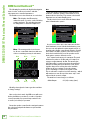
Subwoofer Mode
Subwoofer mode allows you to change
the subwoofer’s polarity.
What does polarity mean, though? A subwoofer
works by literally pumping air as the woofer cone
moves in and out with respect to the cabinet in which
it is housed. It does so according to the low-frequency
portion of the signal it receives from the sound source.
The woofer cone is simply following the waveform
as seen in the sine wave below-lef (Normal).
As the sine wave rises, the woofer cone pushes out.
Likewise, as the sine wave falls, the woofer cone
pulls into the cabinet. A musical signal is much more
complex, of course, but the same principle applies.
Movement of the woofer cone causes air pressure
changes that we perceive as sound.
When invert is selected, the original waveform
is simply reversed 80˚ [See above-right].
Again, the subwoofer cone follows the waveform.
However, this time the woofer cone starts by pulling
into the cabinet followed by the woofer cone pushing
out. If you have ever experimented with a subwoofer’s
polarity, you may not have noticed any changes
to the sound regardless of its position, especially
if you are listening to just the subwoofer. This is normal,
as our ears perceive them both at the same time.
CARDIO DELAY
X-OVER
CONFIG
MAIN MODE
SUBWOOFER MODE
NON-INVERTED
INVERT
NORMAL
SUBWOOFER MODE
NON-INVERTED
INVERT
NORMAL
Polarity comes into play when the DRM8S
subwoofer is paired with a loudspeaker.
Ideally, the woofer cones of the subwoofer and full
range loudspeaker would work together by pushing
and pulling in unison. DRM8S subwoofers are
designed to be used in a broad range of applications.
The flexibility provided by the subwoofer mode
(i.e. polarity) is necessary to ensure that you are
receiving the best possible sound from your system,
regardless of your setup.
Rotate the speaker control knob until the subwoofer
mode you desire – Normal or Invert – is illuminated,
then push to select it. As seen to the lef, we’re going
with Normal.
There’s also a lef-facing arrow. Illuminating
and selecting this simply returns you to the menu.
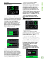
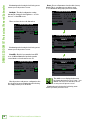
X-Over
DRM8S subwoofers allow you to choose a crossover
frequency for loudspeakers.
There are two choices:
• DRM Top – Choose this if a Mackie DRM
loudspeaker is connected to the system. The crossover
point is set to 90 Hz to work in perfect harmony with
the Mackie DRM loudspeakers. This is what we hope
you choose, thank you for your support!
• Var – Choose this if a non-Mackie DRM
loudspeaker is connected to the system. Here you
can select the crossover, ranging from 40 Hz – 60 Hz.
Rotate the speaker control knob until the crossover
you desire – DRM Top or Var – is illuminated, then
push to select it. If var is selected (as seen below),
the frequency is illuminated and may be changed
by rotating the speaker control knob clockwise
(raise the frequency) and counter-clockwise
(lower the frequency).
In addition to the two crossover selections,
there’s a third and final selection: the lef-facing
arrow. Illuminating and selecting this simply returns
you to the menu.
CARDIO DELAY
CONFIG
MAIN
MODE
X-OVER
CROSSOVER
Variable
120Hz
VAR
DRM
TOP

DRM18S 2000W 18" Professional Powered Subwoofer
14
DRM18S 2000W 18” Professional Powered Subwoofer
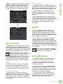
Cardio
Everyone’s busy these days with little-to-no time
for exercise. Fear no more, we’ve got you covered...
at least with cardio. Once selected, you will be
presented with a choice of great cardio exercises,
including:
• Jump Rope
• Squats
• Jogging
• Kickboxing
• Suicide Sprints
• Jumping Jacks
Wouldn’t that be awesome? I need exercise, I’ll go
turn on my DRM8S subwoofer and set the cardio I
want... if only...
No, no, cardio is an “id” shy of cardioid, a way to
“aim” the low-end rumble to have great coverage where
you want it (and away from where you don’t). This
allows you to set up the PA in the most venue-friendly
way.
Typically, subwoofers are omnidirectional, but with
cardioid mode you can aim the DLM8S subwoofer’s
null point (aka “dead spot”) where you don’t want the
deep bass blasted.
In order to change the cardioid mode, first push
the speaker control knob when the cardioid mode
icon is illuminated (see image above). This opens
the cardioid view:
Rotate the speaker control knob until the cardioid
mode you desire – Front or Rear – is illuminated, then
push to select it. As seen above, we’re going with Front.
Like the previous sub-menus, the cardioid mode also
has a lef-facing arrow. Illuminating and selecting
this simply returns you to the menu.
DELAY
MODE X-OVER
CONFIG
MAIN
CARDIO
CARDIOID MODE
FRONT-FACING
REAR
FRONT
Delay
This parameter controls the delay. In other words,
you are going to want to time-align the speakers
throughout the venue so the sound hits everywhere
simultaneously. This is the place.
The delay time ranges from a low of 0.0 ms (f, m)
to a maximum of 00 ms (2.5 f, 34.2 m).
In order to change the delay, first push the speaker
control knob when the delay icon is illuminated (see
image above). This opens the delay view.
From here, rotate the speaker control knob clockwise
until the ms parameter is highlighted.
This is the only parameter that can
be changed here; the f and m delay time
ranges update automatically dependent
on where ms is set.
Push the speaker control knob in to select
the ms parameter followed by rotating the speaker
control knob clockwise (raise the delay time )
and counter-clockwise (lower the delay time).
Like the previous sub-menus, the delay also
has a lef-facing arrow. Illuminating and selecting
this simply returns you to the menu.
CARDIO
X-OVER
CONFIG
MAIN
DELAY
MODE
DELAY
ms
9
ft
10.1
m
3.0
DELAY
ms
9
ft
10.1
m
3.0

Owner’s Manual
15
Owner’s Manual
Configuration
This is where to recall / store settings to memory,
lock access to the settings, select LED screen
brightness and more.
This is similar to what you will see afer first entering
the configuration screen. The backlight and front LED
settings will be illuminated.
To change a setting, just rotate the speaker
control knob until the configuration you desire
to change is illuminated, then push to select it.
These are the choices from top to bottom:
Memory – When memory is selected, settings may be
saved to memory and recalled at a later time. No more
having to reset levels, EQ, voicing, etc. upon every
power-up.
CARDIO
X-OVER
MAIN
MODE
DELAY CONFIG
CONFIGURATION
MEMORY 1 2 3 4 5 6
ABOUT
LOCK PIN 1 2 3 4
BACKLIGHT
FRONT LED
RESET
OFF DIM ON
OFF ON
CONFIGURATION
MEMORY 1 2 3 4 5 6
ABOUT
LOCK PIN 1 2 3 4
BACKLIGHT
FRONT LED
RESET
OFF DIM ON
OFF ON
CONFIGURATION
MEMORY 1 2 3 4 5 6
ABOUT
LOCK PIN 1 2 3 4
BACKLIGHT
FRONT LED
RESET
OFF DIM ON
OFF ON
MEMORY
User memory
RECALL STORE
3:
There are six user memory snapshots which should
be more than enough.
Store – Tap this to store the current settings
to the corresponding memory snapshot.
Please be aware that the new settings
will replace the currently saved settings.
Recall – Tap this to recall the settings of the selected
memory snapshot.
Illuminating and selecting the lef-facing arrow
returns you to the previous screen.
Lock Pin – This is where to lock and unlock the
interface with a secret 4-digit numeric password.
Rotate the speaker control knob until lock pin
is illuminated, then push in to enter lock mode.
From here, rotate the speaker control knob until
the first number you desire is illuminated and press
to select. Follow the same procedure for the next
three numbers.
As seen below, we decided to go with -2-3-4 because
that’s (a “5” shy of) the same code that was used
on Spaceballs. A confirmation dialog helps prevent
accidents. No further changes may be made until
the control access is unlocked.
Unlocking – If you try to make any changes
or select anything, you will be asked to enter
the pin. Here you will need to re-enter the 4-digit
code and push the speaker control knob to unlock.
Secret Squirrel Unlock – If you – or worse, someone
else! – set up a 4-digit lock code and you don’t know
the passcode, there is a quick fix. Simply press and hold
down the speaker control knob down for a few seconds
and it will automatically unlock.
CONFIGURATION
MEMORY 1 2 3 4 5 6
ABOUT
LOCK PIN 1 2 3 4
BACKLIGHT
FRONT LED
RESET
OFF DIM ON
OFF ON
CONFIGURATION
MEMORY 1 2 3 4 5 6
ABOUT
LOCK PIN 1 2 3 4
BACKLIGHT
FRONT LED
RESET
OFF DIM ON
OFF ON
LOCK
Lock user
interface?
YES NO

DRM18S 2000W 18" Professional Powered Subwoofer
16
DRM18S 2000W 18” Professional Powered Subwoofer
Illuminating and selecting the lef-facing arrow
returns you to the previous screen.
Backlight – The third configuration setting
that may be changed is the brightness – or lack
thereof – of the LCD screen.
There are three choices: o, dim and on.
Illuminating and selecting the lef-facing arrow
returns you to the previous screen.
Front LED – Decide if you want the front LED
on or o. When illuminated, push the speaker
control knob to select between on or o.
Like the previous sub-menus, configuration also
has a lef-facing arrow. Illuminating and selecting
this simply returns you to the menu.
CONFIGURATION
MEMORY 1 2 3 4 5 6
ABOUT
LOCK PIN 1 2 3 4
BACKLIGHT
FRONT LED
RESET
OFF DIM ON
OFF ON
CONFIGURATION
MEMORY 1 2 3 4 5 6
ABOUT
LOCK PIN 1 2 3 4
BACKLIGHT
FRONT LED
RESET
OFF DIM ON
OFF ON
Reset – Resets all parameters back to their factory
default. This is a permanent reset with no undo,
so a confirmation dialog helps prevent accidents.
The middle screen displayed above may
be of particular interest. Yes, it’s true – you
CAN do a factory reset and either choose
to save your user presets or not!
Illuminating and selecting the lef-facing arrow
returns you to the previous screen.
CONFIGURATION
MEMORY 1 2 3 4 5 6
ABOUT
LOCK PIN 1 2 3 4
BACKLIGHT
FRONT LED
RESET
OFF DIM ON
OFF ON
CONFIGURATION
MEMORY 1 2 3 4 5 6
ABOUT
LOCK PIN 1 2 3 4
BACKLIGHT
FRONT LED
RESET
OFF DIM ON
OFF ON
RESET
Factory reset
Keep presets?
YES
NO
CONFIGURATION
MEMORY 1 2 3 4 5 6
ABOUT
LOCK PIN 1 2 3 4
BACKLIGHT
FRONT LED
RESET
OFF DIM ON
OFF ON
RESET
Confirm factory
reset?
YES
NO

Owner’s Manual
17
Owner’s Manual
About – Displays the current information about your
subwoofer, including the model, firmware and DSP
versions, temperature, favorite animal and more.
There is really only one reason to go here and that
is if you’ve been directed so by Technical Support.
Protection Circuitry
The DRM8S subwoofer employs a built-in limiter for
less distortion at peak levels. Additional protection
includes automatic thermal shutdown should the amp
overheat. However, with Class-D amp technology, which
is highly-ecient, this should never be a problem.
The protection circuits are designed to
protect the subwoofers under reasonable and
sensible conditions. Should you choose
to ignore the warning signs [e.g. excessive distortion],
you can still damage the speaker in the subwoofer
by overdriving it past the point of amplifier clipping.
Such damage is beyond the scope of the warranty.
Limiting
The driver has its own compression circuit which
helps protect it from damaging transient peaks.
The compressor is designed to be transparent and
is not noticeable under normal operating conditions.
Overexcursion Protection
A subsonic filter circuit just prior to the power
amplifier prevents ultra-low frequencies from being
amplified. Excessive low-frequency energy can damage
the woofer by causing it to “bottom out,” also know
as overexcursion, which is equivalent to a mechanical
form of clipping.
CONFIGURATION
MEMORY 1 2 3 4 5 6
ABOUT
LOCK PIN 1 2 3 4
BACKLIGHT
FRONT LED
RESET
OFF DIM ON
OFF ON
ABOUT
FW : DRM18S v1.0.26
ODO : 56
Temp : 29˚C / 85˚F
Attn : 0.00dB
DSP : DRM18S v402
Thermal Protection
All amplifiers produce heat. DRM loudspeakers are
designed to be ecient both electrically and thermally.
In the unlikely event of the amplifier overheating, a
built-in thermal switch will activate, muting the signal.
When the amplifier has cooled down to a safe
operating temperature, the thermal switch resets
itself, and the DRM8S subwoofer resumes normal
operation.
If the thermal switch activates, try turning down
the level control a notch or two on the mixing console
(or via the Speaker Control knob) to avoid overheating
the amplifier. Be aware that direct sunlight and/or
hot stage lights may be the culprit of an amplifier
overheating.
AC Power
Be sure the DRM8S subwoofer is plugged into
an outlet that is able to supply the correct voltage
specified for your model. It will continue to operate
at lower voltages, but will not reach full power. Be sure
the electrical service can supply enough amperage for
all the components connected to it.
We recommend that a sti (robust) supply of AC
power be used because the amplifiers place high
current demands on the AC line. The more power that
is available on the line, the louder the speakers will play
and the more peak output power will be available for
a cleaner, punchier bass. A suspected problem of “poor
bass performance” is ofen caused by a weak AC supply
to the amplifiers.
Never remove the ground pin on the power
cord or any other component of the DRM8S
subwoofer. This is very dangerous.
Care and Maintenance
Your DRM8S subwoofer will provide many years
of reliable service if you follow these guidelines:
• Avoid exposing the subwoofers to moisture.
If they are set up outdoors, be sure they are under
cover if rain is expected.
• Avoid exposure to extreme cold (below freezing
temperatures). If you must operate the subwoofers
in a cold environment, warm up the voice coils slowly
by sending a low-level signal through them for about
5 minutes prior to high-power operation.
• Use a dry cloth to clean the cabinets. Only
do this when the power is turned o. Avoid getting
moisture into any of the openings of the cabinet,
particularly where the drivers are located.

DRM18S 2000W 18" Professional Powered Subwoofer
18
DRM18S 2000W 18” Professional Powered Subwoofer
Placement
WARNING: Installation should only
be done by an experienced technician.
Improper installation may result in damage
to the equipment, injury or death. Make sure that
the DRM8S is installed in a stable and secure
way in order to avoid any conditions that may be
dangerous for persons or structures.
DRM8S subwoofers are designed to sit on the floor
or stage as the main PA. A socket is provided on top
of the DRM8S for mounting DRM loudspeakers. The
SPM400 is a great pole-mount option. See the hookup
diagrams starting on page 5.
The DRM8S subwoofer may also be flown via its
integrated fly points as detailed on the following
pages. Be sure to read the PA-A2 Eyebolt Installation
Instructions, as well.
NEVER attempt to suspend a DRM8S
subwoofer by its handles.
Check to make sure that the support surface
(e.g. floor, etc.) has the necessary mechanical
characteristics to support the weight of the
subwoofer(s).
When pole-mounting loudspeakers, be sure that they
are stabilized and secured from falling over or being
accidentally pushed over. For stacked scenarios, it is
highly suggested that straps are utilized. Failure to
follow these precautions may result in damage to the
equipment, personal injury, or death.
As with any powered components, protect them from
moisture. Avoid installing a DRM8S in places exposed
to harsh weather conditions. If you are setting them up
outdoors, make sure they are under cover if you expect
rain.
Rigging
WARNING: Installation should only be done
by an experienced technician. Improper
installation may result in damage to the
equipment, injury or death. Make sure that the
DRM8S is installed in a stable and secure way
in order to avoid any conditions that may be dangerous
for persons or structures.
WARNING: The cabinet is suitable for rigging
via its fly points. NEVER attempt to suspend
a DRM8S by its handles.
The fly points of the DRM8S are shown below
while examples of a flown DRM8S are displayed
on the following page.
Rigging Design Practices
Rigging a DRM8S requires determining:
. The rigging methods and hardware that
meet static, shock, dynamic, and any other load
requirements for supporting the subwoofer
from structure.
2. The design factor and required WLL (Working
Load Limit) for this support.
We strongly recommend the following rigging
practices:
. Documentation: Thoroughly document the design
with detailed drawings and parts lists.
2. Analysis: Have a qualified professional, such
as a licensed Professional Engineer, review and
approve the design before its implementation.
3. Installation: Have a qualified professional rigger
do the installation and inspection.
4. Safety: Use adequate safety precautions
and back-up systems.
MP MP MP MP MP MP
MP MP
MPMP
REARBOTTOMTOP SIDE
DRM8S Fly Points
MP = Mounting Point

Owner’s Manual
19
Owner’s Manual
Rigging Hardware and Accessories
Rigging a DRM8S will invariably require hardware
not supplied by us. Various types of load-rated
hardware are available from a variety of third-party
sources. There are a number of such companies
specializing in manufacturing hardware for designing
and installing rigging systems. Each one of these
tasks is a discipline in its own right. Because of
the hazardous nature of rigging work and the potential
liability, engage companies that specialize in these
disciplines to do the work required.
We do oer certain accessory rigging items and some
of them may be used with a variety of products. While
these accessories are intended to facilitate installation,
the wide variety of possible installation conditions and
array configurations do not permit us to determine their
suitability or load rating for any particular application.
We are not in the business of providing complete
rigging systems, either as designers, manufacturers,
or installers. It is the responsibility of the installer to
provide a properly engineered, load-certified rigging
system for supporting the loudspeaker from structure.
DRM8S subwoofers may be individually
flown using a PA-A2 Eyebolt Kit, part
number 205054.
At least three rigging points must be used to
hang each DRM8S subwoofer.

DRM18S 2000W 18" Professional Powered Subwoofer
20
DRM18S 2000W 18” Professional Powered Subwoofer
A Note About Cardioid Operation
DRM8S subwoofers allow for three variants
of cardioid operation:
Double-Stack – Two subs stacked with
the bottom facing away from the audience
and the top facing towards the audience.
Triple-Stack – Three subs stacked with
the bottom facing away from the audience
and the top two facing towards the audience.
Triple Horizontal – Three subs oriented
horizontally with the lef and right subs facing
the audience and the center sub facing away
from the audience.
Be sure to set the cardioid aiming as outlined
on page 4.
Triple-StackDouble-Stack
Triple Horizontal
Page is loading ...
Page is loading ...
Page is loading ...
Page is loading ...
Page is loading ...
Page is loading ...
-
 1
1
-
 2
2
-
 3
3
-
 4
4
-
 5
5
-
 6
6
-
 7
7
-
 8
8
-
 9
9
-
 10
10
-
 11
11
-
 12
12
-
 13
13
-
 14
14
-
 15
15
-
 16
16
-
 17
17
-
 18
18
-
 19
19
-
 20
20
-
 21
21
-
 22
22
-
 23
23
-
 24
24
-
 25
25
-
 26
26


Mackie DRM 18S User manual
- Category
- Supplementary music equipment
- Type
- User manual
- This manual is also suitable for
Ask a question and I''ll find the answer in the document
Finding information in a document is now easier with AI
Related papers
-
Mackie DRM12A OM User manual
-
Mackie DRM18S-P Owner's manual
-
Mackie DRM215 User manual
-
-
-
-
Mackie SRT215 User manual
-
-
Mackie MX Series OM Owner's manual
-
Other documents
-
 American Acoustic Development M Series User manual
-
AMC SUB2 User manual
-
 SoftWall Finishing Systems SW6423352129 Installation guide
-
Advent ADE-21PE Quick start guide
-
 Audience ClairAudient 1+1 V1 Owner's manual
-
Tannoy VMB WALL HANGING MOUNT Quick start guide
-
-
OSD Audio ACOUSTIC-10 Owner's manual


