Page is loading ...

pentair.com
INSTALLATION AND
OPERATION MANUAL
L-1589 Rev. B (12-10-19)
HYDRAULICALLY DRIVEN CENTRIFUGAL PUMPS
WITH FORCEFIELD TECHNOLOGY
9314C SERIES
9314S SERIES
KEEP FOR FUTURE REFERENCE
Pentair
375 5th Ave. NW, New Brighton, MN 55112
Phone: (651) 766-6300 -OR- 800-424-9776
Fax: 800-323-6496
www.pentair.com
EC REP
EU Authorized Representative:
QNET BV Hommerterweg 286
6436 AM Amstenrade, The Netherlands
KvK Zuid-Limburg 14091511

2
Contents
EU Language Manuals ............................................................................................................................................................ 3
Introduction .............................................................................................................................................................................. 4
Description ........................................................................................................................................................................... 4
Intended Uses...................................................................................................................................................................... 4
Purpose of Manual .............................................................................................................................................................. 4
Misuses ................................................................................................................................................................................ 5
PumpIdentication..............................................................................................................................................................5
Pump Technical Data .............................................................................................................................................................. 6
DimensionalSpecication...................................................................................................................................................6
PumpSpecications............................................................................................................................................................7
Performance Charts ............................................................................................................................................................ 8
Fluid Pumping Applications ............................................................................................................................................... 9
Tools .................................................................................................................................................................................. 9
Lifting, Transport, and Intermediate Storage ................................................................................................................ 9
Assembly and Installation ..................................................................................................................................................... 10
Assembly ........................................................................................................................................................................... 10
Installation .......................................................................................................................................................................... 10
Control Systems .................................................................................................................................................... 13
Commissioning, Start-Up, Operation, Shut-Down ................................................................................................................ 14
Information ......................................................................................................................................................................... 14
Start-up, Operation, Shutdown .......................................................................................................................................... 14
Maintenance and Servicing ................................................................................................................................................... 16
Information ......................................................................................................................................................................... 16
Disposal ............................................................................................................................................................................. 16
Cleaning ............................................................................................................................................................................. 16
Maintenance, Routine Servicing, and Inspection ........................................................................................................ 16
Troubleshooting..............................................................................................................................................................17
Replacement Parts ................................................................................................................................................. 18
Model 9314 Part Illustrations and Repair Kits ..................................................................................................... 19
LimitedWarrantyon Hypro/ShuroAgriculturalPumps& Accessories..........................................................................................21

3
EU Languages
DO NOT attempt to install or operate your pump before reading the manual. Original copies of the manual for Hypro
pumpsareprovidedinEnglish.Tondacopyinyournativelanguage,gotowww.hypropumps.com.
Vor dem Ablesen des Handbuches versuchen Sie NICHT, Ihre Pumpe zu installieren. Originale des Handbuches fur
Hypro-PumpenwerdenaufenglischzurVerfugunggestellt.ZueineKopieinIhrerMuttersprachenden,zu
www.hypropumps.com zu gehen (German)
N’essayez pas d’installer votre pompe avant de lire le manuel. Des exemplaires originaux du manuel pour des pompes
de Hypro sont fournis en anglais. Pour trouver une copie dans votre langue maternelle pour aller a
www.hypropumps.com (French)
NON tentare di installare la vostra pompa prima di leggere il manuale. Esemplare originale del manuale per Hypro
pompe sono in inglese. Per trovare una copia nella vostra lingua andare a www.hypropumps.com (Italian)
Непытайтесьустановитьвашнасосдочтенияруководства.Оригинальныекопииэтогоруководствадлянасосы
Hyproнаанглийскомязыке.Найтикопиюнавашроднойязыкперейтикwww.hypropumps.com(Russian)
NO intente instalar su bomba antes de leer el manual. Copias originales del manual para Hypro se provee de bombas
en ingles. Para encontrar una copia en tu idioma nativo ir a www.hypropumps.com (Spanish)
NIEprobowaćinstalowaćpompyprzedjejodczytanieminstrukcji.OryginalnekopieinstrukcjiobsługipompHyprosą
dostarczanewjęzykuangielskim.Abyuzyskaćkopięwtwoimojczystymjęzykuprzejdźdowww.hypropumps.com
(Polish)
Takmayacalışmayınokumadanoncepompanınmanuel.OrijinalkopyalarınıHypropompalarıicinIngilizceolarak
sunulmuştur.Birkopyasınıbulmakicinyereldilgitwww.hypropumps.com(Turkish)
Nao tente instalar a bomba antes de ler o manual. As copias originais dos manuais para Hypro bombas sao
fornecidos em Ingles. Para encontrar uma copia em sua lingua nativa ir para www.hypropumps.com (Portuguese)
VERGEETNIETuwpompvoorhetlezenvanhethandboek.ExemplarenvandehandleidingvoorHypropompenzijn
beschikbaarinhetEngels.Opzoeknaareenexemplaarinuweigentaalganaarwww.hypropumps.com(Dutch)

4
Introduction
Description
Pentair’s Line of Hypro centrifugal pumps are designed for agricultural and industrial spraying and transfer of a variety of
uids:water,insecticides, herbicides, wettable powders, emulsives, liquid fertilizers, etc. Hypro Series 9314 hydraulic
motor-driven centrifugal pumps provide smooth performance. They can be conveniently mounted on the
tractor or sprayer, becoming part of the vehicle’s hydraulic system and freeing the PTO for other uses.
Intended Uses
Hyprocentrifugalpumpsareintendedforcreatingorboostingdynamicpressureinapproveduids.Hyprocentrifugal
pumps should never be used to pump liquids above 140°F (60°C), or below 34°F (1°C). For pumps equipped with
hydraulicmotors,thepumpshouldnotberunifthehydraulicoiltemperatureexceeds135°F(57°C).Anyusesoutside
ofthosespeciedinthismanualareconsideredmisusesandareprohibited.ContactPentairtechnicalservicewithany
questionsregardingspecicacceptableuses.
Purpose of Manual
Pentair has provided this manual to provide instructions and requirements that must be met when installing, using and
maintainingthepump(s)identiedonthecover.
If the product is sold, the seller must pass this manual onto the new owner.
The following special attention notices are used to notify and advise the user of this product of procedures that may be
dangerous to the user or result in damage to the product.
ATTENTION
Attention is used to notify of installation, operation, or maintenance information that is important but not safety related.
Thissymbolisusedtodenotethepresenceofanelectricalhazardthatwillresultinpersonalinjury,deathorproperty
damage.
Thissymbolisusedtodenotethepresenceofahazardthatwillresultinpersonalinjury,deathorpropertydamage.
California Proposition 65 Warning --Thisproductandrelatedaccessoriescontainchemicalsknowntothe
State of California to cause cancer, birth defects or other reproductive harm.

5
Misuses
Pentair’s line of Hypro centrifugal pumps are designed to operate effectively within the speed, pressure, and
environmental ranges speciedinthismanual.Operatingapumpoutsideoftheserangeswillvoidthewarrantyandcould
causedamagetoproperty,seriouspersonalinjury,ordeath.Youmustobservethefollowingsafetyguidelines:
• DO NOT run the pump faster than the maximum recommended speed
• DO NOT run the pump or hydraulic motor higher than the maximum recommended pressure
• DO NOT run pumps when the liquid has exceeded the maximum or minimum temperature limit (See Intended Uses)
• DO NOT pump non-approved liquids (See Fluid pumping Applications)
• DO NOT use pumps in explosive environments
• DO NOT pump water or other liquids intended for human consumption
• DO NOT operate a pump with a gasoline engine in an enclosed area
• DO NOTattachapipe,hoseorttingstothepumpthatisnotratedforthemaximumpressureofthepump(outlet)or
vacuum of the pump (inlet)
• DO NOToperateanyPentairpumpundertheinuenceofdrugsoralcohol
• DO NOT run a pump in reverse of its intended rotation
• DO NOT run the pump dry
Pump Identication
Pentair uses serialized labeling to enable users to precisely identify the pump’s manufacturing date.
Serial Number:
First and second digits: year (16 = 2016)
Third through fth digits: consecutive day of the year the pump was manufactured.
Sixth through tenth digits: unique pump serial number.

6
Pump Technical Data
9314C(S)-M08, -M08Y, M10, -M10Y, and -M16
Pump Dimensions
9314C-
9314S-
Motor Dim. Inch mm
(all)
A 9.74 247
B 9.55 243
C 5.24 133
D 3.81 97
E 3.93 100
M08,M08Y F 11.53 293
M10,M10Y F 11.65 296
M16 F 12.03 305
(all)
G 5.26 134
H 5.25 133.4
I 2.63 66.7
J 1.60 41
øK 0.44 11.1
L 5.22 133
9314CU(SU)-M08, -M08Y, M10, and -M16
Pump Dimensions
9314CU-
9314SU-
Motor Dim. Inch mm
(all)
A 9.64 245
B 9.87 251
C 5.56 141
D 3.81 97
E 3.93 100
M08,M08Y F 11.91 302
M10,M10Y F 12.03 306
M16 F 12.41 315
(all)
G 5.64 143
H 5.25 133.4
I 2.63 66.7
J 1.60 41
øK 0.44 11.1
L 5.12 130
A
B
E
C
L
D
I
H
G
J
2X
Ø
K
F
A
B
E
L
D
C
I
H
G
J
2X
Ø
K
F

7
Pump Technical Data
9314C(S)-M08, -M08Y, M10, -M10Y, and -M16
Pump Dimensions
9314C-
9314S-
Motor Dim. Inch mm
(all)
A 9.74 247
B 9.55 243
C 5.24 133
D 3.81 97
E 3.93 100
M08,M08Y F 11.53 293
M10,M10Y F 11.65 296
M16 F 12.03 305
(all)
G 5.26 134
H 5.25 133.4
I 2.63 66.7
J 1.60 41
øK 0.44 11.1
L 5.22 133
9314CU(SU)-M08, -M08Y, M10, and -M16
Pump Dimensions
9314CU-
9314SU-
Motor Dim. Inch mm
(all)
A 9.64 245
B 9.87 251
C 5.56 141
D 3.81 97
E 3.93 100
M08,M08Y F 11.91 302
M10,M10Y F 12.03 306
M16 F 12.41 315
(all)
G 5.64 143
H 5.25 133.4
I 2.63 66.7
J 1.60 41
øK 0.44 11.1
L 5.12 130
Pump Specications
Pump
Hydraulic
Motor
Inlet Max
PSI [BAR]
Hydraulic
Motor
Outlet Max
PSI [BAR]
Max
Flow
Rate
(GPM)
[LPM]
Max
Pressure
(PSI)
[BAR]
Max
Hyd.
Flow
(GPM)
[LPM]
Pump
Ports
Hydraulic
Ports
Dry
Weight
Mounting
Bolts
9314C-M08
3000
[207]
100
[6.9]
227[859] 132[9.1] 14[53]
2” NPT Inlet
1-1/2” NPT
Outlet
SAE -8 Inlet
SAE -10
Outlet
40 lbs
[18kg]
2X 3/8”
OR M10
9314S-M08
9314C-M10
233[882]
150
[10.3]
17[64.4]
9314S-M10
9314C-M16
232[878] 138[9.5] 24[90.8]
9314S-M16
9314C-M08Y
227[859] 132[9.1] 14[53]
SAE -8 Inlet
SAE -10
Outlet
SAE -6 Case
Drain
9314S-M08Y
9314C-M10Y
233[882]
150
[10.3]
17[64.4]
9314S-M10Y
Pump
Hydraulic
Motor
Inlet Max
PSI [BAR]
Hydraulic
Motor
Outlet
Max PSI
[BAR]
Max
Flow
Rate
(GPM)
[LPM]
Max
Pressure
(PSI)
[BAR]
Max
Hyd.
Flow
(GPM)
[LPM]
Pump
Ports
Hydraulic
Ports
Dry
Weight
Mounting
Bolts
9314CU-M08
3000
[207]
100
[6.9]
227[859] 132[9.1] 14[53]
2” Universal
Flange Inlet
2” Universal
Flange Outlet
SAE -8
Inlet
SAE -10
Outlet
40 lbs
[18kg]
2X 3/8”
OR M10
9314SU-M08
9314CU-M10
233[882]
150
[10.3]
17[64.4]
9314SU-M10
9314CU-M16
232[878] 138[9.5] 24[90.8]
9314SU-M16
9314CU-M08Y
227[859] 132[9.1] 14[53]
SAE -8
Inlet
SAE -10
Outlet
SAE -6
Case
Drain
9314SU-M08Y
9314CU-M10Y
233[882]
150
[10.3]
17[64.4]
9314SU-M10Y

8
Performance Charts
Allspecicationsandperformancedataarebasedonwaterasacarrieruid.
Note:Thedashedportionofthepumpcurvesisoutsidetherecommendedoperatingrange,andcanonlybeachieved
withsufcientNPSHa.RefertoInstallationInstructions.

9
Fluid Pumping Applications
Application
Pump Materials Compatibility
Impeller Pump Housing
Noryl GTX Cast Iron Stainless Steel
Weed Control Chemicals X X X
Insect Control X X X
BrushControl X X X
Pest Control Chemicals and Fumigants X X X
Liquid Fertilizers X - X
Powdered Fertilizers X X X
Fluid Transfer X X X
Acids - - X
Flammable liquids, sewage, and clean water should never be pumped through a Hypro pump. Hypro pumps are not
designedtobeusedascleanwaterpumpsasdenedin10CFRParts429and431.
Tools
Hypro 9314 Series centrifugal pumps and mounting assemblies are designed with metric fasteners.
Lifting, Transport, and Intermediate Storage
Packaging Descriptions and Unpacking Instructions
• Hypro centrifugal pumps are shipped in cardboard boxes for safe transporting.
• When pumps are shipped in large quantities, they may be put on a pallet to allow for easy storage, lifting and handling.
• Beforeliftinganypumporpallet,determinetheweightoftheitembylookingattheattachedpackingslipstoestablish
what lifting equipment should be used.
• Beforeinstallingthepump,determineifallthecomponentsarepresentandundamaged.Ifthepumpismissing
components, contact customer service immediately.
• Oncethepumpisunpacked,disposeofthepackaginginamannercompliantwithlocalandnationalregulations.
Lifting Instructions
• BeforeattemptingtoliftaHypropump,ensurethatthesurroundingworkingareaisfreeofhazardswhichcouldcause
injuryordamagetoproperty.
• Duringliftingoperations,anypersonnelnotinvolvedintheliftshouldnotentertheworkingarea.
• Ifliftinghooks,ropeorchainsarebeingusedforalift,theymustbefreeofdamageandberatedtocarry150%ofthe
weight of the load to be lifted.
• Always wear steel-toed shoes and cut-resistant gloves when attempting to lift.
• Whenliftingandcarrying,alwayskeepthepumpclosetoyourbody.(SeeFigure1)
• Whenstartingthelift,bendyourkneesandkeepyourbackstraight.(SeeFigure1)Tighteningthestomachmuscleswill
helpkeepyourbackstraight.
• Duringthelift,useyourlegstodothework.Neveruseyourback,andmakesureyourlegsareatleastshoulder-width
apart. (See Figure 1)

10
Figure 1
Transport
• All Hypro pumps are capable of being transported by air, sea, rail or motor vehicle. When the pump is shipped, ensure
that the pump is moved in accordance with local and national laws and is properly secured to prevent unwanted
movementwhichcouldcausedamagetopersonorproperty.Priortoshipping,alluidsshouldberemovedfromthe
pump.
Storage
• New pumps in their boxes can be stored several years as long as the port plugs are not removed. Once the plugs
have been removed, if the pump is not to be used for an extended period of time (i.e. more than 30 days), the pump
must be winterized as described in the Cleaning section of this manual.
Assembly and Installation
Assembly
• This pump comes completely assembled.
Installation
BeforeattemptingtoinstallyourHyprocentrifugalpump,itisimperativetoreadandunderstandthefollowing:
• InstallationofaHypropumpshouldonlybeperformedbyatechnicianhavingtheknowledgeandskillsnecessary
toinstallthepumpwithouttheriskofpropertydamageorinjury.
• When handling Hypro pumps one should wear steel-toed shoes and protective gloves in order to protect the feet
in the event the pump is dropped and protect the hands from any sharp surfaces on the pump or chemicals.
• Pumping systems must be installed in accordance with Pentair installation instructions. Failure to do so will void
yourwarrantyandcouldcausedamagetoproperty,seriouspersonalinjury,ordeath.
• Electricalpowercablesandpumphosesmustberoutedwherethereisnoriskofpersonneltripping,walkinginto,
or falling because they have been routed in areas where personnel are expected to move. Electrical power cables and
pump hoses should be routed according to local and national standards.
• Itistheinstaller’sresponsibilitytoensurethatACelectric-drivemotors,Hypropumps,andmetalworkofsupport
structures are bonded to earth (ground), per local and national standards.
• It is the installer’s responsibility to conduct earth continuity tests between AC electric-drive motors, Hypro pumps,
andmetalworkofsupportstructuresandearthaccordingtoEN60204-1:2006/A1:2009,oritssupersedingstandard,to
conrmthatallcomponentsthatneedtobeconnectedtoeartharesatisfactorilybonded.
• Itistheinstaller’sresponsibilitytoconductelectricaltestsinaccordancewithEN60204-1:2006/A1:2009,orits
supersedingstandard,onnishedpumpassemblies.
• All connections to electrical components must be number, symbol, or color-coded generally as recommended by
EN60204-1:2006/A1:2009,oritssupersedingstandard.
• Installers must provide hydraulic components that are capable of withstanding maximum source pressure.
• Theworkingpressuremustbecontrolledbyapressurereliefvalvethatisadjustedtooperateatamaximum
pressure of the hydraulic motor.
• If a rigid plumbing system is to be used on a Hypro centrifugal pump, the system must be properly aligned with
the inlet and outlet ports.

11
• Theworkingpressureinthehydraulicssystemmustbecontrolledbyapressurereliefvalvethatisadjustedto
operateat10%ofthemaximumsystempressure.
• Wheninstalling,adjustingorremovingaHyprocentrifugalpump,ensurethattherearenoobjectswhichcanfall
ontheinstallerandmakecertainthatallmachinerytowhichthepumpistobeattachedisturnedoff.
• Pumps must be installed in a location where they are accessible for any necessary maintenance.
• Whenhydraulicpowerisused,thesystemshouldcontainaquickdisconnectcouplingthatcanbedisconnected
to isolate the pump.
Standard Mounting
• Inordertopreventinjuryordamagetoproperty,allHypropumpsshouldbeproperlymountedtoasolidbasewhere
thereisnodangerofthepumpfallingorbreakingloose.AllHypropumpscomewithmountingholeswhichallow
bolts to be put into the pump so it can be secured to a sturdy base. When mounting your Hypro centrifugal pump, be
sure to use bolts and nuts which are compatible with any chemicals that may come into contact with them as well as
choosing the correct grade of bolt based on the pump weight and any expected loads. Pumps should be mounted
as close to the liquid source as possible. Non self-priming pumps must be mounted below the liquid level to function
properly.
Pump Plumbing
• To achieve maximum pump performance, pump inlet and outlet lines should be at least the same size as their
respective port, and should have as few restrictions as possible. Pump plumbing must be capable of withstanding the
maximumsuctionandpressuregeneratedbythepump.Pumpsuctionlinemustalsobefreeofairleaks.Usegood
quality suction hose that will not be collapsed by suction.
• For best priming results, the recommended orientation for the outlet port is pointing straight up. The upper most vent
plugcanberemovedandaventlinecanbeinstalled.Thislinepreventsairlockandallowsthepumptoprimeitself
by bleeding off trapped air. Avoid any dips or bends in the suction line plumbing that could trap air.
• NPSHR (Net Positive Suction Head Required) represents the minimum pressure required at the suction port of the
pumptopreventcavitation.Cavitationoccurswhenthispressurefallsbelowthevaporpressureoftheuidbeing
pumped. Cavitation results in reduced pump performance, damage to internal components, excessive vibration, and
reduced pump life.
• NPSHR curves are provided for each pump model in the Pump Performance section of this manual. The values are
provided in feet.
• TodeterminetheNPSHa(NetPositiveSuctionHeadAvailable),usethefollowingformulai:
where:SG=Specicgravityofliquid(water=1.0)
p=Barometricpressure(inchesofmercury)
p = vapor pressure of liquid in psi absolute
p = gauge pressure at pump suction
• To achieve optimal NPSHa, the pump inlet plumbing should be at least the same diameter as the inlet port of the
pump. The inlet plumbing must also have as few restrictions (elbows, tees, valves, or other transitions) as possible.
Thepumpinletmustalsobebelowtheuidlevelinthetank.TheNPSHamustbegreaterthantheNPSHRforthe
pump to prevent cavitation.
sg
vp
a

12
Hydraulic Installation
• Prior to installation, refer to the tractor or sprayer manual and determine what type of hydraulic system is being used. The
threetypesofsystemsinclude:
• Open center systems
• Closed center (Pressure-Compensated) systems
• Closed center Load Sensing (Flow and Pressure-Compensated) systems
•Thehydraulicmotormustbecorrectlyconguredandsizedforthehydraulicsystem:
• Open center systems
• Excess oil from the hydraulic pump must be bypassed around the motor
•Builtinbypassoptioninmotorendplate,orseparatebypassvalveinstalledinthelinefeedingthe
motor inlet.
• Use the largest motor possible
• Closed center (Pressure-Compensated) systems
• Motor should be sized to achieve system hydraulic pressures of (typically) 1800 to 2100 psi
• Use the smallest motor possible
• Closed center Load Sensing (Flow and Pressure-Compensated) systems
•Nospecialrequirementforbypassormeteringorices
Hydraulic system plumbing
•Wheninstallingthehydraulicmotorintothetractororsprayer’shydraulicsystem,makesurethatnodirtorliquidgetsinto
the hydraulic motor.
KEEP ALL HYDRAULIC CONNECTIONS CLEAN.
• Ensure return line is connected to low pressure return port on the tractor recommended for hydraulic motors, the ports
areidentiedonthemotorcasting.Hydraulicsupplylinesshouldbeatleastthesamesizeasthehydraulicmotorportorlarger.
•Standardmodelscomeequippedwithacheckvalveportadaptoronthemotoroutlet,thatshouldnotberemoved.
Hooking up the motor in the wrong direction will damage the hydraulic seal.
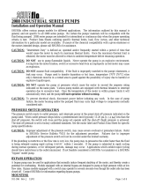
Ref.
No. Description
1 TankLid
2 Vent Line
3 Jet Agitator
4 Shut-offBallValves
5 Centrifugal Pump
6 Spray Control Console
7 Centrifugal Pump Control
8 ManifoldBoomValve
9 Flowmeter
10 JetTurretNozzleBody

13
•Hydraulicbackpressureinthereturnlinemustbelessthan100psi[6.9bar]topreventreducedseallife.Pressures
under50psi[3.4bar]arerecommended..
•Themotorcasedrain,availableon“Y”seriespumps,isrecommendedtominimizethepressureactingonthehydraulic
motor oil seal, and extend the life of the oil seal. The case drain line must be connected directly to the hydraulic reservoir
with no restrictions, and the case drain port on the motor must always be oriented upward.
THE CASE DRAIN PORT ON HYDRAULIC MOTORS MUST NEVER BE PLUGGED.
• Metering Orices
Attention: DO NOT use metering orices if the system is a load-sensing (ow-compensated) closed center
system
•Meteringoricesforthe9314SeriespumpsarenotrequiredforClosedcenter(Pressure-Compensated)systemsifthe
motor is properly sized to achieve typical hydraulic system pressures of 1800 to 2100 psi.
Control Systems
• All pump systems with electric or hydraulic power sources are required to have a control system which meets all local
and national standards.
• For more detail on a typical system installation, see preceding subsections of the “Assembly and Installation” section of
this manual.

14
Commissioning, Start-Up, Operation, Shutdown
Beforeattemptingtostartyourpump,thefollowingmustbeunderstoodandfollowedtoensuresafeoperation.
Information
• When running Hypro centrifugal pumps, it is essential that operators use hearing protection as the sound levels
can reach levels of 80 decibels.
• When handling Hypro pumps, one should wear steel-toed shoes and protective gloves in order to protect the feet
in the event the pump is dropped and protect the hands from any sharp surfaces on the pump or chemicals.
• OnlyauthorizedoperatorshavingtheknowledgeandskillnecessarytosafelyuseaHypropump,orany
equipment the pump is connected to, may run the pump.
• Whensprayingmanually,itisrecommendedthatchemical-resistantfacemasksandclothingbeworntoprevent
anychemicalsfromcomingintocontactwiththeskinorbeinginhaled.
• When spraying manually, always spray upwind of yourself as long as the sprayed chemical will not drift into the
vicinity of other people.
• Wheninstalling,adjustingorremovingaHyprocentrifugalpump,ensurethattherearenoobjectswhichcanfall
ontheinstallerandmakecertainthatallmachinerytowhichthepumpistobeattachedisturnedoff.
• Hypro centrifugal pumps should only be used on tractors or tow-behind spray platforms which have electrically
conductivetiresinordertoreducetheriskofelectrocution.
• NeveroperateaHyprocentrifugalpumpoutsidewhilethereisachanceofgettingstruckbylightning.
• Never leave electrical wires or plumbing components where they can be a tripping hazard or become entangled
inamovingcomponent.Ideally,electricalcables,hoses,pipesandttingsshouldberoutedoverhead.Intheevent
electrical wiring must be routed over the ground, operators are required to use rubber ramps if they cross a gangway.
• Hypro centrifugal pumps should not be used if the ambient light is below 200lux.
Only use approved chemicals in your pump. For a complete list of approved chemicals, see the “Fluid
Pumping Applications” section. Failure to follow this warning will void your warranty and could lead to property
damage, serious injury or death.
Start-up, Operation, Shutdown
Before Starting the Pump
• Ensure all unnecessary personnel are clear of the area.
• Forinitialsetupandtestofyoursystem,itisrecommendedtostartwithcleanwaterinsteadofchemicals,andconrm
thesystemandplumbingconnectionsareleakfree.
• Ensurethatthereisuidinthesourcetankorsupplyline.Donotrundry.
• Checklinestrainerfordebrisorclogs.Removeanyfound.
• Checkallplumbingconnectionstomakesuretheyaretight.
• Checkpowersourceandconnections.
• Checkthatallvalvesandregulatorsaresettothedesiredsettingandarefunctioningproperly.
• Ensure all hoses are properly positioned and are not damaged in any way.
Priming the Pump
The 9314 Series pump must not be run dry.
Tohelpprimethepump,keeptheinletorsuctionlineasshortaspossiblewithaminimumofbends,elbows,andkinks.
Makesureallconnectionsaretightanddonotleakair.Thepumpmusthavetheinletlineandpumpoodedwithliquid
before starting the pump. On pumps with ForceField™ Technology (wet seal), dry run cannot exceed 15 minutes in one
singleevent,orthereisariskofdamagetothepumpmechanicalseals.

15
Starting, Operation and Shutdown of the Pump (Hydraulic)
Open Center Systems - All Models
Adjusting Centrifugal Pump Output
ATTENTION M08, M10, and M16 motors have bypass screw fully closed from the factory. M04 and M05 motors have
bypass screw set at 1-1/2 turns from fully closed from the factory.
1. Openthebypassadjustmentscrew2-1/2turnsfromfullyclosedandsecureitinplacewiththebypassjamnut.
2. Start the tractor. Leave the directional valve in the neutral position and allow hydraulic oil to circulate for approximately
10 to 15 minutes or until adequately warmed.
3. Prime the centrifugal pump with all valves open. (See Priming the Pump.)
4. Refertosprayermanufacturer’smanualtosetsprayingpressureandow.Tochangetheoworpressuregenerated
bythepump,turnthebypassscrewonthehydraulicmotor.Besuretosecurethebypassjamnutafterany
adjustment.
5. To shutdown, return directional valve to neutral and allow the pump to come to a gradual stop.
When bypassing hydraulic oil, a large amount of heat can be generated which will damage the tractor’s hydraulic
system.Besuretomonitortheoiltempwhenbypassinghydraulicoil.
Closed Center (Pressure-Compensated)
Adjusting Centrifugal Pump Output
1. Openthebypassadjustingscrewinthehydraulicmotorthree(3)turnsandsecureitinplacewiththebypassjamnut.
2. Start the tractor and allow hydraulic oil to circulate for approximately 10 to 15 minutes or until adequately warmed
3. Closeandlockdownthebypassadjustingscrewinthehydraulicmotor.
4. Prime the centrifugal pump with all valves open. (See Priming the Pump.)
5. Refertosprayermanufacturer’smanualtosetsprayingpressureandow.Tochangetheoworpressuregenerated
bythepump,slowlyadjusttractor’sowcontrolvalve.
6. Toshutdown,thepumpmovetheselectorforthetractorspoolvalvetotheoatpositionandallowthepumptocome
to a gradual stop.
If the pump is not brought to a gradual stop, the sudden change in hydraulic pressure and pump RPM could cause
damage to the pump’s drive system.
Closed Center (Load-Sensing) Systems
Adjusting Centrifugal Pump Output
1. Closeandlockdownthebypassadjustingscrew,ifequipped,inthehydraulicmotor.
2. Setthetractorhydraulicowcontrolvalveforminimumhydraulicoilowtotheremoteoutlet(Tortoiseposition).
3. Start the tractor and allow the hydraulic oil to circulate for approximately 10 to 15 minutes or until adequately warmed.
4. Prime the centrifugal pump with all valves open. (See Priming the Pump.)
5. Refertosprayermanufacturer’smanualtosetsprayingpressureandow.Tochangetheoworpressuregenerated
bythepump,slowlyadjusttractor’sowcontrolvalve.
6. Toshutdownthepump,movetheselectorforthetractorspoolvalvetotheoatpositionandallowthepumptocome
to a gradual stop.
If the pump is not brought to a gradual stop, the sudden change in hydraulic pressure and pump RPM could cause
damage to the pump’s drive system.

16
Maintenance and Servicing
Information
• All maintenance should be done when machinery is stationary and has been isolated from its energy sources.
It is dangerous to perform maintenance while machinery is still connected to its power source. Machinery should be
isolated from its electrical, hydraulic or gas engine power source.
• BesuretoreleaseallpressurefromthesystembeforeperforminganysortofmaintenanceonaHypropump.
• DO NOT perform service or maintenance to the pump, or attached components, until the pump unit is below
109°F(43°C).
• The lubrication of this pump unit has been done at the factory prior to shipping.
• When handling Hypro pumps, one should wear steel-toed shoes and protective gloves in order to protect the feet
in the event the pump is dropped and protect the hands from any sharp surfaces on the pump or chemicals. If the
pump is being repaired while the pump is in service, eye protection should also be worn.
Any hazardous liquids should be disposed of in a manner which complies with local and national regulations. Never dump
uidsontotheground.
Disposal
WhendisposingofaHypropump,besuretoremovealluidsfromthepumpbeforescrapping.Theseuidsshouldbe
disposedofinamannerwhichcomplieswithlocalandnationalregulations.Neverdumpuidsontotheground.Oncethe
pumpisfreeofalluids,itmaybescrappedinaccordancewithlocalandnationallaws.
Cleaning
Yourpumpwilllastlongerandgivebestperformancewhenproperlytakencareof.Properpumpcaredependsonthe
liquidbeingpumpedandwhenthepumpwillbeusedagain.Aftereachuse,ushpumpwithaneutralizingsolutionforthe
liquidjustpumped.Followwithacleanwaterrinse.Thisisespeciallyimportantforcorrosivechemicals.Itisgoodpractice
to clean the pump after each use to prevent deposits from forming and damaging the pump. For infrequent use and before
long periods of storage, drain pump thoroughly. Open any drain plugs, remove suction hose from liquid, and blow pump
drywithair.Anantifreeze/rustinhibitorshouldbeinjectedintothepumpbeforebothportsarepluggedandthepumpis
stored.Plugallportstokeepoutairuntilpumpisusedagain.
Maintenance, Routine Servicing, and Inspection
PREVENTATIVE MAINTENANCE CHECKLIST
Check Daily Weekly Annually
(<1000 machine hrs)
Clean Filters X
WaterLeaks X
Plumbing X
Chamber Fluid X
• Eachsystem’smaintenancecyclewillbeexclusive.Ifsystemperformancedecreases,checkimmediately.
• Dutycycle,temperature,quality,typeofuidbeingpumped,andinletfeedconditionsallaffectthelifeandservice
interval of the pump.
• Beforeattemptingtoserviceyourpump,besurethatitisdisconnectedfromallenergysources.

17
Troubleshooting
If the proper Hydraulic Pump Unit has been selected according to Pentair recommendations, and the unit has been
correctly plumbed into the hydraulic system, operation should be quite satisfactory. If spraying performance is
unsatisfactoryorhydraulicsystemheatisexcessive,checkthefollowingtroubleshootingguideforpossibleproblemsand
solutions.
Troubleshooting Guide
Symptom Probable Cause(s) Corrective Action
Pump does not prime Leakinsuctionline Checkhoseandttingsforleaksand
correct
Obstruction in suction line Inspect hose for obstructions and
remove
Suctionhosestucktotank Cut a notch or “V” in end of suction
hose
Clogged strainer Checkstrainerandcleanregularly
Low discharge Pump not primed Remove topmost vent plug from
face of pump and run pump to expel
trapped air (See Installation Instruc-
tions).
Leakinsuctionline Checkhoseandttingsforleaksand
correct
Blockedsuctionline Inspect suction line and strainer, and
repair as necessary
Impeller plugged Inspect and clear obstruction.
Undersize inlet line or collapsed hose Suction line should be the same diam-
eter as inlet port of pump or larger.
Hydraulicbypassneedsadjustment See Installation instructions
Pump worn Repair Pump
Pump will not turn Hydraulichoseshookedupincorrectly See Installation instructions
Motor seized - contamination Repair or replace hydraulic motor.
Hydraulic system overheating Hydraulicbypassneedsadjustment See Installation
Insufcienthydraulichosesize See Installation
Replacement Parts
The following drawings show the pumps and their replacement parts. Only genuine replacement parts should be used.
Failure to follow this warning can result in damage to property, serious injury or death. If the pump malfunctions or
isdefective,itshouldbesentbacktoPentairforservice.

18
Model 9314 Part Illustrations and Repair Kits
Includes Models 9314C(S) -M08, -M08Y, M10, -M10Y, and -M16
9314CU(SU) -M08, -M08Y, M10, -M10Y, and -M16
2
3
4
6
7
8
9
10
11
1
20
35
25
5
39
12
1
13
14
15
16
17
18
21
22
23
24
26
27
29
28
34
33
32
31
37
36
30
19
38
2A

19
Ref.
No.
Qty.
Req’d.
Part No. Description
1 5 2406-0016 Drain/Vent Plug (SS)
2 1 0157-9310C Pump Casing (9314CU)
2 1 0157-9310SM Pump Casing (9314SU)
2A 1 0154-9310C Pump Casing (9314C)
2A 1 0154-9310SM Pump Casing (9314S)
3 1 2253-0015 Impeller Nut
4 1 0400-9316 Impeller
5 1 1720-0292 O-ring, Large
6 6 2220-0124 SocketHeadCapScrew
7 1 0751-9310 Plate, Front Chamber
8 1 1720-0294 O-ring, Small
9 1 2535-0015 Membrane
10 1 2120-0069 Mechanical Seal, Double (Silicon Carbide)
11 1 0752-9310C Mounting Flange
12 4 2210-0194 Hex Head Cap Screw
13 2 2230-0051 SocketSetScrew
14 1 1410-0137 Tone Wheel
15 1 1820-0039 Retaining Ring
16 1 2000-0017 BallBearing
17 1 1410-0145 Spacer
18 1 2104-0011 Motor Lip Seal
19 2 2029-0010 ThrustBearingAssy
20 1 1610-0072 Shaft Key
21 1 0533-2510 Shaft (M08/M10 Motor)
21 1 0533-2512 Shaft (M16 Motor)
22 1 1810-0011 Retaining Ring
23 1 1610-0031 Roll Pin (M08/M10 Motor)
23 1 1610-0055 Roll Pin (M16 Motor)
24 1 0150-2517C MotorBody(std)
Ref.
No.
Qty.
Req’d.
Part No. Description
24 1 0150-2515C MotorBody(Yseriescasedrain
motors)
25 4 2210-0209 Hex Head Cap Screw
26 2 1720-0110 O-ring
27 1 3900-0022 Gerotor (M08 Motor)
27 1 3900-0048 Gerotor (M10 Motor)
27 1 3900-0024 Gerotor (M16 Motor)
28 1 1600-0084 Dowel Pin, Small (M08/M10 Motor)
28 1 1600-0085 Dowel Pin, Small (M16 Motor)
29 1 1600-0095 Dowel Pin, Large (M08/M10 Motor)
29 1 1600-0096 Dowel Pin, Large (M16 Motor)
30 1 0720-2603 Gerotor Housing (M08 Motor)
30 1 0720-2604 Gerotor Housing (M10 Motor)
30 1 0720-2606 Gerotor Housing (M16 Motor)
31 1 3220-0029 BypassScrew(StdMotor)
32 1 2250-0038 LockNut,Bypass(StdMotor)
33 1 2270-0027 Washer,Bypass(StdMotor)
34 1 1700-0047 Gasket,BypassScrew(StdMotor)
35 1 0254-2500C2 Motor End Plate (Std Motor)
35 1 0254-2500C3 MotorEndPlate(Yseriesmotors,no
Bypass)
36 4 2270-0039 Washer
37 4 2220-0135 SocketHeadCapScrew(M08Motor)
37 4 2210-0204 SocketHeadCapScrew(M10Motor)
37 4 2210-0208 SocketHeadCapScrew(M16Motor)
38 1 1720-0262 O-ring,Checkvalve
39 1 3320-0052A MotorCheckValveAssy(includeso-ring)
n/a 1 2160-0138 Seal Chamber Fluid (not shown,
pump requires 10.5 oz)
NOTE: When ordering parts, give quanti-
ty, part number, description and complete
model number. Reference numbers are
used ONLY to identify parts in the drawing
and are NOT to be used as order numbers.
Parts Kit No. 3430-0949
Contains:Oneeachballbearing(Ref.16),motor
shaftseal(Ref.18),threadsealgasket(Ref.34),
washer (Ref. 33), two each motor housing o-rings
(Ref. 26), and port adaptor o-ring (Ref. 38)
Pump Repair Kit No. 3430-0948
Contains:O-rings(Ref.5&8),mechanicalseal
(Ref. 10), Membrane (Ref. 9), Pump Chamber
Fluid, and seal installation tool
Pump Repair Kit No. 3430-0947
Contains:sameas3430-0948,exceptinstalla-
tion tool not included.
Hydraulic Motor Part Nos.
2500-0801C(M08Ymodels)
2500-0802C (M08 models)
2500-1001C(M10Ymodels)
2500-1002C (M10 models)
2500-1602C (M16 models)
Replacement Chamber Fluid #2160-0138
Contains:23ozofchamberuid,pre-mixed.

20
Rev 12/22/18
EC Declaration of Incorporation
Manufacturers Name: Pentair Flow Technologies, LLC
Manufacturers’ Address: 375 Fifth Avenue NW,
New Brighton, MN 55112, USA
Declare that the partially complete machinery described below conforms to applicable health and safety requirements of Emission Directive
2010/26/EU and of Parts 1 of Annex I of Machinery Directive 2006/42/EC. This partly completed machinery must not be put into service until the
equipment into which it is to be incorporated has been declared in conformity with the provisions of these directives. Confidential technical
documentation has been compiled as described in Annex VII Part B of Machinery Directive 2006/42/EC and is available to European national
authorities on written request. If a request is received, documentation will be transmitted either electronically or by post. Clauses 1.1.4, 1.1.7,
1.1.8 Section 1.2, Clauses 1.3.5, 1.3.6, 1.3.7, 1.3.8.1, 1.3.8.2, 1.3.9, 1.4.1, 1.4.2.1, 1.4.2.2, 1.4.2.3, 1.4.3, 1.5.2, 1.5.7, 1.5.12, 1.5.14, 1.5.16, 1.6.2, 1.7.1.1, 1.7.1.2,
1.7.2, and 1.7.4.2 are clauses of Machinery Directive 2006/42/EC that have not been met, but could be applicable and must be addressed during
installation by a third party.
Description: PENTAIR Pump
Type: Roller Pumps
Series Numbers 1502, 1700, 4001, 4101, 6500, 7560, 7700
Type: Centrifugal Pumps
Series Numbers 1442P, 1539, 1540, 1542P, 1543P, 1550, 90XX, 9202, 9203, 9205, 9206,
9208, 9262, 9263, 9253, 9302, 9303, 9305, 9306, 9307, 9308, 9313, 9314,
9316, 9342P, 9343P, 9742P, 15HPS, 93HPS
Type: Cleanload Assembly
Series Numbers 3376, 3378
Type: Piston/Plunger Pumps
Series Numbers 5315C, 5320C, 5321C, 5322C, 5324C, 5325C, 5330C, 53702, 53703
The following standards have either been referred to or been complied with in part or in full as relevant:
ENISO 12100 Machinery Safety - General principles for design - Risk assessment and risk reduction
EN809-1998 + A1 2009 Machinery Safety - Pumps and pump units for liquids - Common safety requirements
EN ISO 13732-1 Machinery Safety - Ergonomics of the thermal environment
EN ISO 3744:2010 Acoustics - Determination of sound power levels and sound energy levels of
noise sources using sound pressure
EN ISO 11202/A1 1997 Machinery Safety - Noise emitted by machinery and equipment
EN 12162:2001+A1:2009 Machinery Safety - Liquid pumps - Safety requirements-Procedure for hydrostatic testing
EN ISO 4254-6:2009 Machinery Safety - Sprayers and liquid fertilizer distributors
EN 60204-1:2006/A1:2009 Machinery Safety - Electrical Equipment of Machines
Name .……………...…………………………………………… Position…..……………………….…..………
Signature …………………………………………..……………. Date…..……..………………………..……….
Place of Signing…………………………………………………………………………………………………….…..
Rev 12/22/18
EC DECLARATION OF INCORPORATION
/