Page is loading ...

Invented and Manufactured
By
1411 S. Roselle Rd
Schaumburg, IL 60193
Phone 847-923-0002 Fax 847-923-0004
www.AltronicsInc.com

1
During use of this system the Oxygen sensor becomes very hot. Do
not touch sensor. Do not place sensor near combustible materials.
Failure to do so can result in serious injury.
Do not expose Oxygen sensor to hot exhaust gases unless sensor is
connected to the O2ALERT control unit and the O2ALERT is
powered. Hot exhaust gas will quickly damage a non-powered
Oxygen sensor. THEREFORE IT IS RECOMMENDED THAT
POWER IS APPLIED TO O2ALERT AT THE SAME TIME OR
BEFORE IGNITION.
O2ALERT is to be used for racing purposes only.
Altronics Inc. is not responsible for the use or misuse of the
O2ALERT product.

2
Table of Contents
WARNINGS____________________________________ 1
FEATURES 3
OVERVIEW____________________________________ 4
INSTALLING THE SYSTEM ________________ 5
CONTROLLER___________________________ 5
WIDEBAND OXYGEN SENSOR____________ 6
EGT SENSOR_____________________________ 7
OTHER SENSORS________________________ 8
Analog INPUTS and OUTPUTS_____ 8
SYSTEM SETUP 9
Calibration___________________________ 11
OPERATING THE SYSTEM 12
RECORDING_____________________________ 12
PLAYBACK______________________________ 13
DOWNLOAD_____________________________ 13
INSTALLING THE DOWNLOAD SOFTWARE______ 14
OPERATING SOFTWARE 15
WARRANTY 17
TECHNICAL SUPPORT 17
ERROR CODES_________________________________ 17
TROUBLE SHOOTING__________________________ 18
APPENDIX 19

3
O2ALERT FEATURES
Records Up to 2 Wide Band Air/Fuel Sensors
Records Engine RPM
Records Battery Voltage
Records Thermocouple Temperature (optional)
Records 2 Analog Voltage inputs (optional)
Air/Fuel Voltage Outputs (optional)
Warning Output with Settable Air/Fuel Ratio
On screen Readout.
PC Not Needed
Adjustable Sample Rate
Download and Data Analysis Software
Starts on RPM or Switch

4
OVERVIEW
The O2ALERT system is designed to measure and record Air/Fuel ratio
(AFR) for an internal combustion engine. An AFR of 14.7 pounds of air
to 1 pound of fuel is the optimal ratio for a gasoline engine. This is
equivalent to a Lambda of 1 and is also referred to as the stoichiometric
ratio. The stoichiometric ratio is achieved when all available fuel is
consumed by air in the combustion cycle. When Lambda is less than 1
the engine is rich and the combustion cycle leaves unburned fuel in
exhaust. When Lambda is greater than 1 the engine is lean and the
combustion cycle leaves unused Oxygen in the exhaust. The O2ALERT
uses a Wideband Oxygen sensor to measure the amount of fuel in the
exhaust to determine the Air/Fuel Ratio.
Typically an engine makes maximum power with a Lambda of .8 to .9
Stoichiometric values for various fuels:
Gasoline 14.7
Methanol 6.4
Ethanol 9.0
CNG 17.2
Diesel 14.6
E85 9.7

5
INSTALLING SYSTEM
Mount O2ALERT Unit in an easily accessible area on vehicle.
Connections to green terminal strip: (use #18 gauge wire)
GND – Ground - chassis ground.
PWR – POWER +12 or +16 volt DC source (vehicle battery). Fuse
at 10 amps quick blow.
RPM – Engine RPM – connect to rpm output from ignition
(DIGITAL Tach Signal Only. Do NOT connect to coil)
1R – EGT 1 red side
1Y – EGT 1 yellow side
A1 – Analog 1 input (5 volt DC max!)
A2 – Analog 2 input (5 volt DC max!)
WRN – Warning Output – Normally Open contact, switched to
Power (vehicle battery) upon warning activation. Connect to device
you want to control when warning is activated. (Warning Light, NOS
disable, Retard timing, shut off ignition). Output can only supply up
to 2 amps, so if more power is needed connect warning output to a
higher power control relay.
Air/Fuel 1 – Connect supplied cable and Oxygen Sensor.
Air/Fuel 2 – Connect second supplied sable and Oxygen Sensor.
Use following drawings to install Air/Fuel Oxygen Sensors.
USB Port

6
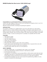
Installing Weldment and Oxygen sensor
Position and weld bung in top or side of exhaust tube. Do not mount in
bottom of tube where condensation will damage sensor. Sensor can be
mounted anywhere in exhaust system from approx 8 inches from exhaust
port in header or exhaust manifold to collector or tail pipe.
Install upstream from catalytic converters.
Install downstream from turbo chargers.
NOTE: Installing close to exhaust port:
The temperature of the sensor at the bung can not exceed 900 ˚F or
damage will occur. Therefore is it recommended to provide a heat sink
made out of a small piece of copper sheet 0.060”thick. 4-5”. Drill ¾”
hole in center of sheet and mount as shown.
Ox
yg
en Senso
r
Heat Sink
2 o’clock
10 o’clock
Condensation
Exhaust tube
Ox
yg
en Senso
r
Bun
g

7
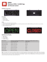
EGT (Thermocouple) WELDMENT INSTALLATION
1) Weldments should be placed equal distant to headers flanges. Up to 4” away is
acceptable. Weldments should be placed the same
distance away from the flange
on each header, this is very important. They should also be in the same position in
each header. Weld in small increments around the weldment as to not get the
weldment excessively hot, which will cause it to warp.
2) After weldment is welded in place, screw on the lower section of compression
fitting.
3) Using the hole in the compression fitting as a guide, drill a 3/16” hole through the
header tube.
EGT (Thermocouple) BAYONET INSTALLATION
1) BAYONET should be placed the same
distance away from the flange on
each v header, this is very important. Up to 4” away is acceptable. They
should also be in the same position in each header.
2) Drill a 1/4” hole through the header tube. Tighten clamp onto header at
desired location.

8
OTHER SENSORS
The O2ALERT allows for recording up to 2 analog inputs. These inputs
can be from sensors which can measure EGT, Pressure, Vacuum,
Position, Acceleration, Air/Fuel, or any other 0-5 volt signal.
The O2ALERT can also output Air/Fuel Ratios in voltage form. This is
useful in connecting to other data acquisition equipment or vehicle ecu’s.
Contact Altronics Inc. for more info 1-888-464-2587 or visit our website
www.AltronicsInc.com

9
SET UP
To enter SETUP you must press and release the MODE key when
“O2ALERT” appears on the LCD Display immediately after powering
up the system.
After SETUP is entered the screen will prompt you to set the number of
engine cylinders:
NUM OF CYL->_
Use the UP/DOWN buttons to set the appropriate number of cylinders.
Then press SELECT.
Next select the Start on RPM:
START ON RPM->Y or N
Using the UP/DOWN buttons your can set to start recording off of an
engine RPM or Manual.
Then press SELECT.
If you select Y (Yes) you will be prompted to set the start RPM:
RPM->(value)
Using the UP/DOWN buttons your can set the RPM to start Recording.
Then press SELECT.
Next set the Warning AFR:
WARN AFR->(value)
Using the UP/DOWN buttons your can set the air/fuel ratio that will
activate the Warning Output.

10
Next set the Warning RPM:
WARN RPM->(value)
Using the UP/DOWN buttons your can set the RPM value that will allow
activation of the Warning Output.
Note: This feature allows the warning output to only be activated when
the engine rpm is above entered value. This allows system to be armed
and recording when engine is not running or at idle.
Then press SELECT.
Next set the FUEL TYPE:
FUEL TYPE->Y or N
Using the UP/DOWN buttons to confirm setting fuel type.
Then press SELECT.
If you select Y (Yes) you will be prompted to set the fuel type:
Using the UP/DOWN buttons your can select compatible fuel types.
Then press SELECT.
Next set the Sample Rate:
SAMPLE RATE->1, 10, 100
Using the UP/DOWN buttons your can set the Sample Rate to 1, 10 or
100 samples per second. The slower the rate the longer the units will
record and vice-versa. 1-200 minutes, 10-20 minutes, 100-2 minutes.
Then press SELECT.

11
CALIBRATION
DO NOT CALIBATE A NEW SYSTEM! They are already factory
calibrated.
The following calibration is done in open air only. The sensor should be
removed from exhaust and left in the open air. Before calibrating you
can check if the sensor is out of calibration by selecting PLAYBACK ->
A/F1 or A/F2 -> REALTIME. This will show the real-time AFR of the
selected sensor. The open air AFR should be 100. If the reading is not
100 then you should calibrate the sensor using the following procedure.
After selecting sample rate you will be prompted with the option to
Calibrate sensor.
CALIBRATE-> Y or N
Using the UP/DOWN buttons your can choose Y to calibrate sensor.
Then press SELECT.
The display will then show CALIBRATING! This can take a couple of
minutes to complete calibration. After calibration is complete verify that
the open AFR is 100.
NOTE: to verify sensor and system is operating, simply breathing on
sensor should cause AFR to change to a value of less then 100.

12
OPERATING THE SYSTEM
After applying power to the system a greeting will be displayed as
follows:
O2ALERT
By Altronics
VERSION 1.0
INITIALIZING!
Then will show:
RECORD
By using the UP/DOWN Buttons you can select one of the operating
modes RECORD, PLAYBACK, or DOWNLOAD. You can enter into
any of these modes by then pressing the SELECT button.
RECORD
It is recommended that you go through SETUP before RECORDING
data.
Depending on how the system was configured in SETUP the display will
read either Recording! or Armed!. If Start On RPM was enabled then
the display will read Armed! until the preset RPM has been reached.
Once the RPM has been reached the display will change to say
Recording!. If Start On RPM was disabled the system will say
Recording! immediately upon selecting the RECORD mode.
The unit will record until one of the following conditions has been met.
1) Max recording time has been reached.
2) The MODE key is pressed
3) The RPM dropped below 500RPM and Start On RPM was
enabled.
If WARNING is activated during recording the a WARNING! Message
will be displayed alternating with the Recording! message
After recording has stopped the display will read Complete!
If a WARNING was activated during recording it will show the Air/Fuel
Sensor number that tripped the warning after recording is complete.

13
PLAYBACK
After entering the PLAYBACK mode you can choose which channel
you want to view by using the UP/DOWN buttons. Once the channel
you want is displayed press the SELECT button.
Now you can choose between 4 Playback modes. MIN/MAX, STEP,
REALTIME, or LAUNCH. Press the SELECT button after using the
UP/DOWN buttons to enter the playback mode desired.
MIN/MAX: Shows the Minimum and Maximum value of channel and
time during recording that value occurred
STEP: Show the value of channel and time at each time interval during
recording. Use the UP/DOWN buttons to scroll through the time of
recording.
REALTIME: Shows the real time value of channel.
NOTE: Warning will activate during real time operation if warning AFR
is met. This is useful if system will be operating for long periods of time
and recording is not necessary.
LAUNCH: Shows the channel value at beginning of recording.
Press MODE button to jump back to and select another channel to
DOWNLOAD
Download should only be selected when system is connected to and
prompted by the O2ALERT software running on you Personal
Computer.
Press MODE button to exit DOWNLOAD mode.

14
INSTALLING SOFTWARE
IMPORTANT: INSTALL SOFTWARE IN FOLLOWING ORDER
ONLY!
The O2ALERT transfers data to your PC through a USB (Universal
Serial Port). In order to install the “DRIVER” which allows the
O2ALERT to communicate with your PC the following steps must be
performed.
After USB is installed then O2ALERT software can be installed.
The USB driver will attach itself to one of your computers Comports.
After driver is installed you will need to determine which Comport it has
installed itself to.
There are two files located on the O2ALERT CDROM that detail the
USB installation. View one of the following files depending on which
Windows operating system you have to help with installation.
USB Install Win 98-XP.DOC
USB Install Win 2000.DOC
1) Power up both O2ALERT and PC.
2) Place O2ALERT CDROM in PC’s drive.
3) Connect USB cable to O2ALERT and then to PC.
4) Your PC should automatically find new hardware and start driver
installation process.
5) When prompted choose to Search for Driver and select CDROM
drive.
6) Select Next, then Finish to complete installation of USB driver
7) Now right mouse click on MY COMPUTER and select
properties.
8) Select Hardware/Device Manager and go to the PORTS (Com
&LPT) section.
9) Click + sign and you should see listed USB Serial Port (COM #).
10) Remember which COM # it is.
11) Now install O2ALERT Software
12) Run the Setup.exe file on the O2ALERT CDROM
13) Follow Prompts on screen.

15
OPERATING SOFTWARE
To run the O2ALERT software simply select O2ALERT from the Programs directory
in the Start menu, as you would for any other program installed for Windows.
You can also create a shortcut to run the O2ALERT program from your desktop. Refer
to Windows help on creating shortcuts.
Before selecting the Download or Real Time Button select the correct Comport #
Download:
When Download is selected a File Select pop up menu will appear. You should enter
the name of a file to keep the data you are going to download.
Ex: Indy_run_1.dat
All files should be kept in the C:\Program Files\O2ALERT\Runs directory
After entering a file name and selecting OK another pop up panel will appear with
directions for downloading. The O2ALERT should now be connected to the computer
with the cable provided.
You will see the word Downloading appear on the O2ALERT display and also see
“Downloading in Progress” appear on your computers monitor.
Wait unit it reaches 100%. When downloading is complete the Run Information box
will appear and you can enter any parameters you may want for that run. Then press
Save Run Info.
O2ALERT will return to its main menu and you can select to review the run. The Data
Analysis interface will now appear on your monitor.
You can now click on the enabled channels and then hit GRAPH to plot them out.
Note: The small color boxes next to the enabled channel can be selected, which will
then bring up a color chart, so you can select a different color to plot out the channel.
CURSOR: You can use your mouse to click on any point on the graph and a cursor
will automatically be set showing the time and data value of that point. You can now
use the arrow keys to move back and forth along the graph.
SMOOTHING: This feature allows you to set the amount of filtering for the graph. If
there is noise in the plot of a channel to can use you mouse and click on the Smoothing
slider to increase the amount of filtering. Click on GRAPH again to see a smother plot.

16
SET START OF RUN: You can set time = 0 at any point on the graph by left mouse
clicking on at desired place on graph, then hit SET START OF RUN Button and then
hit GRAPH button.
ZOOM: Hold CTRL key and Left mouse click on graph to ZOOM
PAN: Hold CTRL and SHIFT key and Left mouse click and drag on graph to PAN.
Review:
When Review is selected a File Select pop up menu will appear. You should select one
of your previously downloaded runs for reviewing from the C:\Program
Files\O2ALERT\Runs directory.
After selecting your run the Data Analysis interface will appear on your monitor
Review Multiple Run:
When Review Multiple Runs is selected two File Select pop up menus will appear to
select base run and then to select Compare run.
After selecting your runs the Data Analysis interface will appear on your monitor
Real Time:
Allows for viewing real time data of all enabled channels in O2ALERT on PC. Select
Correct Comport before pressing Real Time.

17
WARRANTY
The O2ALERT by is warranted for 1 Year against
any defect in materials and workmanship from date of purchase. ALL
WARRANTIES AND GUARANTEES ARE VOID if the O2ALERT
enclosure is opened or altered. Sensors are not warranted.
shall not be liable for injury, consequential, or other
types of damages resulting from the use or misuse of the O2ALERT
TECHNICAL SUPPORT
Email: [email protected]
When sending a unit in for repair or update: Fill out a “Service Form”
which is available from the Technical Support Section of our website->
www.altronicsinc.com

18
ERROR CODES and TROUBLE SHOOTING
Error codes will be shown after the system initializes on the respective
Air/Fuel Channel (AF1 or AF2 sensor error). The following table shows
definition of error codes.
Error Code Error Possible Causes Fix
1 Overheated
Sensor
1. Sensor to close to
exhaust port.
2. Sensor damaged
3. Cable damaged.
4. O2Alert heater
control damaged
1.Install heat sink on
sensor.
2.Replace Sensor
3.Replace Cable
4.Send o2alert in for
repair.
63,2 Heater Shorted 1. Sensor damaged
2. Cable damaged
1.Replace Sensor
2.Replace Cable
127 Open Circuit 1.Cable connectors
loose
2. Sensor damaged
1.Tighten Connectors.
2.Replace Cable/Sensor
191 Heater Shorted 1.Sensor damaged
2.Cable damaged
1.Replace Sensor
2.Replace Cable
207,243,252 Sensor Short
Ground
Sensor damaged Replace Sensor
223,247,253 Low Voltage Low Battery Verify 12 volts to system,
Charge Battery
239,251,254 Sensor Short
Battery
Sensor Damaged Replace Sensor
Note on error code 1: If the O2Alert is displaying error code 1, you can
do the following check to verify if the overheating problem in being
caused by hot exhaust or if it is a system problem.
Turn system ON without engine running. Leave system ON for at least
five minutes. If error code does not come on, then problem is due to
sensor mounted to close to exhaust port and needs to have heat sink
installed.

19
APPENDIX
MAIN MENU
1 RECORD
2 SETUP
A. NUMBER OF CYLINDERS
B. CYLINDER ORDER
C. START ON RPM
a. RPM VALUE
D. WARNING AFR
E. WARNING RPM
F. FUEL TYPE
G. SAMPLE RATE
H. CALIBRATE
3 PLAYBACK
A. CHANNEL SELECT
b. MIN/MAX
c. STEP
d. REALTIME
e. LAUNCH
4 DOWNLOAD- Download data base into PC
/